check engine ISUZU KB P190 2007 Workshop Repair Manual
[x] Cancel search | Manufacturer: ISUZU, Model Year: 2007, Model line: KB P190, Model: ISUZU KB P190 2007Pages: 6020, PDF Size: 70.23 MB
Page 2047 of 6020

ENGINE MECHANICAL (C24SE) 6A-33
HYDRAULIC VALVE LIFTER
1. Hydraulic Valve Lifter
1. Oil reservoir
2. Piston with ball head (moving)
3. Pressure cylinder (fixed)
4. Check ball
5. Pressure chamber
6. Oil feed
BACK TO CHAPTER INDEX
TO MODEL INDEX
ISUZU KB P190 2007
Page 2050 of 6020

6A-36 ENGINE MECHANICAL (C24SE)
Clean
All sealing surfaces, drill holes in cylinder head bolts.
Check cylinder block and cylinder head for plane surface
according to the corresponding operations.
Installation
1. Install cylinder head sealing with marking "OBEN/TOP"
facing upwards and to right side of engine.
2. Install cylinder head on cylinder block.
3. Install hydraulic valve lash adjuster, pressure parts and rocker arm - molybdenum disulphate paste.
4. Install camshaft housing-Sealing Compound TB-1207C or equivalent.
Important!
Use new cylinder head bolts.
Screw in bolts until they rest on cover.
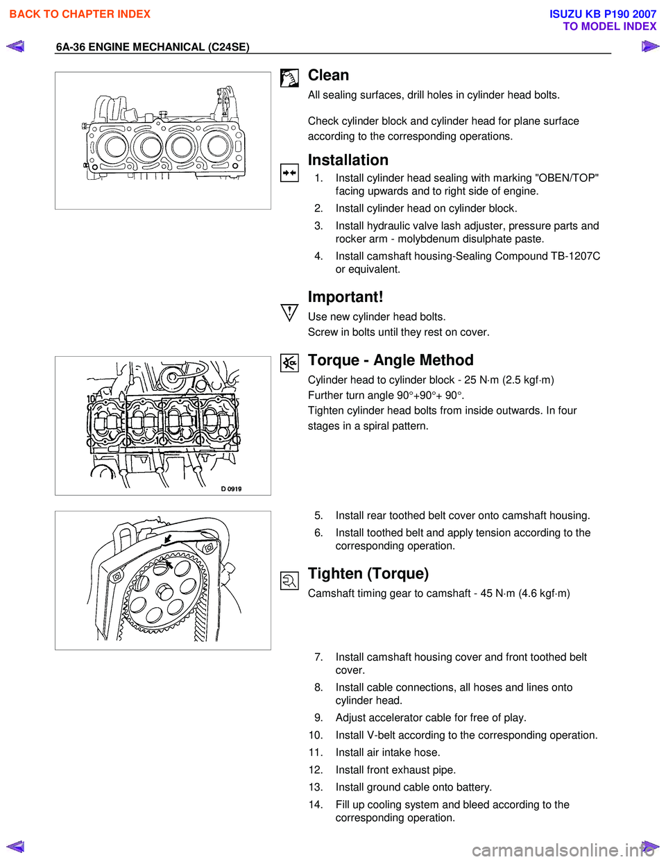
Torque - Angle Method
Cylinder head to cylinder block - 25 N ⋅m (2.5 kgf ⋅m)
Further turn angle 90 °+90 °+ 90 °.
Tighten cylinder head bolts from inside outwards. In four
stages in a spiral pattern.
5. Install rear toothed belt cover onto camshaft housing.
6. Install toothed belt and apply tension according to the corresponding operation.
Tighten (Torque)
Camshaft timing gear to camshaft - 45 N ⋅m (4.6 kgf ⋅m)
7. Install camshaft housing cover and front toothed belt
cover.
8. Install cable connections, all hoses and lines onto cylinder head.
9. Adjust accelerator cable for free of play.
10. Install V-belt according to the corresponding operation.
11. Install air intake hose.
12. Install front exhaust pipe.
13. Install ground cable onto battery.
14. Fill up cooling system and bleed according to the corresponding operation.
BACK TO CHAPTER INDEX
TO MODEL INDEX
ISUZU KB P190 2007
Page 2053 of 6020

ENGINE MECHANICAL (C24SE) 6A-39
Camshaft Housing, Check for Plane Surface
Clean
Sealing surfaces.
Inspection
Check length and width of sealing surface for deformation and
diagnosis for warpage and use straight edge feeler gauge.
Measure
Height of camshaft housing (sealing surface to sealing
surface).
Dimension I: (74.0 mm)
Cylinder Head, Removal and Installation
Important
Only remove cylinder head with engine cold (room
temperature).
Removal
1. Remove the alternator, power steering and V-belts.
Removal
2. Loosen the fastening bolts from alternator.
3. Loosen the lower alternator fastening bolt by swinging the alternator to the rear.
Removal
4. Remove the front toothed belt cover.
5. Remove the toothed belt from camshaft pulley.
See operation "Timing Check and Adjust".
BACK TO CHAPTER INDEX
TO MODEL INDEX
ISUZU KB P190 2007
Page 2054 of 6020

6A-40 ENGINE MECHANICAL (C24SE)
Removal
6. Remove the camshaft housing cover and camshaft pulley by counter-holding at the hex head of camshaft.
Removal
7. Remove the fastening bolts from camshaft housing.
Removal
8. Remove the exhaust pipe from exhaust manifold.
9. Loosen the cylinder head bolts spirally from the outside inwards (first 1/4, then 1/2 revolution).
Removal
1. Remove the camshaft housing from cylinder head.
2. Remove the cam followers, thrust pieces and hydraulic valve lifters.
Note the allocation.
3. Remove the cylinder head.
Clean
Sealing surfaces, bores and threads of cylinder head bolts.
Inspection
Check cylinder head and cylinder block for plane surfface-see
operations “Cylinder Head, Check for Plane Surface” and
“Cylinder Block, Check for Plane Surface.”
BACK TO CHAPTER INDEX
TO MODEL INDEX
ISUZU KB P190 2007
Page 2059 of 6020

ENGINE MECHANICAL (C24SE) 6A-45
Valve Seating, Mill
Place cylinder head on block of wood.
Inlet and exhaust, Guide Drift and Valve Seat Cutter 5-8840-
2593-0.
Valve seat-45 °, side face, upper correction-30 °, side face
(arrows on cutter).
Valve seat width:
Inlet-1.0 to 1.5 mm/0.04 to 0.06 in.
Exhaust-1.7 to 2.2 mm/0.072 to 0.088 in.
Inspection
Valve stem projection-use 5-8840-2596-0.
Important!
If dimension “A” is exceeded, use new valves.
Check valve stem projection again. If dimension “A” is
exceeded, replace cylinder head.
Cylinder Head, Overhaul
Cylinder head disassembled.
Valve, Grind
Important!
Ensure that there are no crater-like burns on the valve cone.
Regrinding possible once or twice.
Grinding of valve stem end is not permitted.
Angle at valve head-44 °
Inspection
Check valve stem projection as shown 5-8840-2596-0.
Valve, Grind in
Lubricate valve stem, use fine-graining grinding paste.
Lift up valve from seat rythmically using valve grinding tool (1)
for distribution of grinding paste.
BACK TO CHAPTER INDEX
TO MODEL INDEX
ISUZU KB P190 2007
Page 2060 of 6020

6A-46 ENGINE MECHANICAL (C24SE)
Inspection
Check contact pattern ( I) on valve seat and in cylinder head.
Clean
Valves, valve guides, cylinder head.
Flywheel
Removal
1. Remove transmission and clutch.
2. Remove flywheel while locking with 5-88400-446-0.
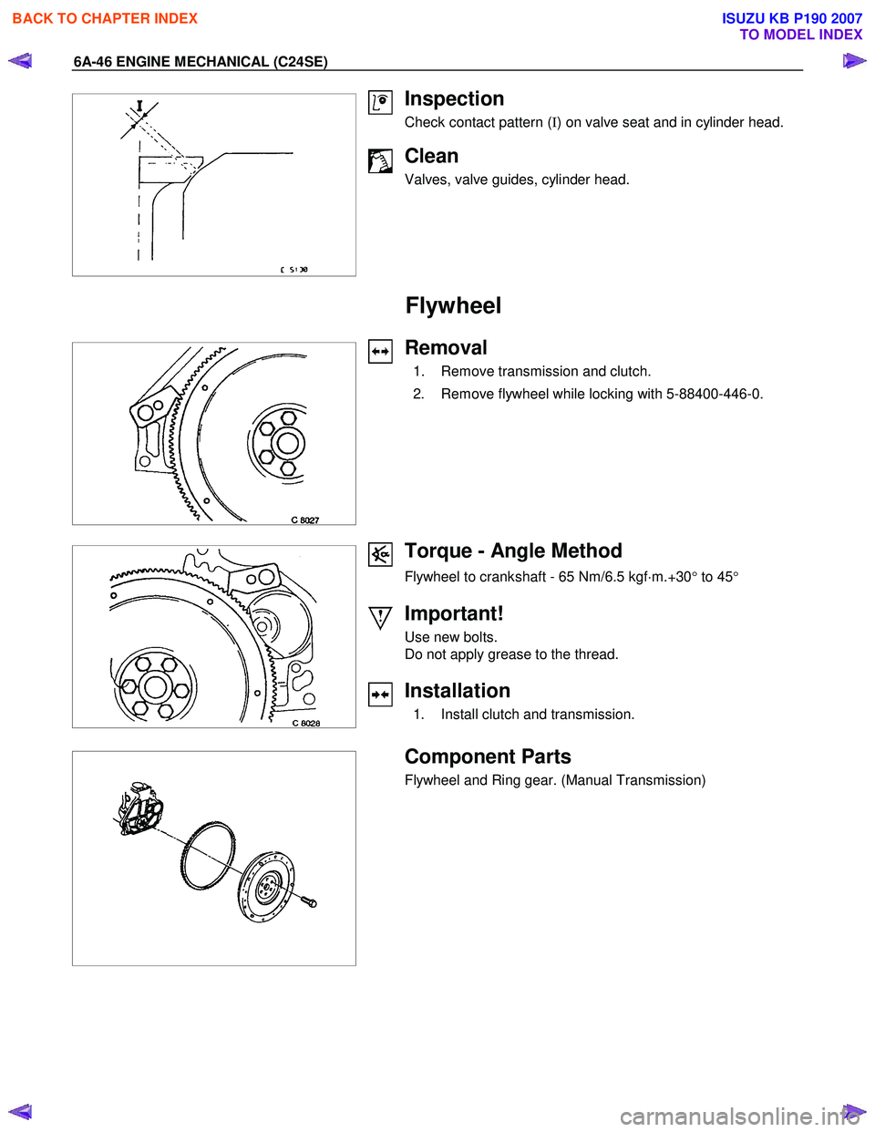
Torque - Angle Method
Flywheel to crankshaft - 65 Nm/6.5 kgf ⋅m.+30 ° to 45 °
Important!
Use new bolts.
Do not apply grease to the thread.
Installation
1. Install clutch and transmission.
Component Parts
Flywheel and Ring gear. (Manual Transmission)
BACK TO CHAPTER INDEX
TO MODEL INDEX
ISUZU KB P190 2007
Page 2064 of 6020

6A-50 ENGINE MECHANICAL (C24SE)
Clean
Sealing surfaces.
013RW 004
Installation
1. Apply a bead of Sealing Compound, TB120TC or eguivalent to joint of oil pump.
2. Apply the recommended light gasket to the oil pan fitting surface as shown in the illustration.
3. Install the bearing bridge.
4. Install baffle plate, or reuse baffle plate.
Caution
Baffle plates can be retrofitted without difficulty - replace baffle
plate.
5. Install oil intake pipe to oil pump and oil intake pipe bracket to cylinder block.
6. Install oil pan and new gasket to cylinder block and insert bolts with Locking Compound 15 10 177 (90 167 347).
Maximum assembly time including torque check is 10
min.
7. Return the power steering unit (and front axle [4 ×4 model
only]).
8. Install the crossmember.
Tighten (Torque)
Oil intake pipe to oil pump -8N ⋅m (0.8 kgf ⋅m)
Oil intake pipe bracket to cylinder block - 6 N ⋅m (0.6 kgf ⋅m)
Oil pan to cylinder block - 8 N ⋅m (0.8 kgf ⋅m)
Bearing bridge to cylinder block – 8 N ⋅m (0.8 kgf ⋅m)
BACK TO CHAPTER INDEX
TO MODEL INDEX
ISUZU KB P190 2007
Page 2071 of 6020

ENGINE MECHANICAL (C24SE) 6A-57
Inspection
Out-of-round (run-out)-middle bearing shell removed when
mounting on front and rear bearing.
Permissible out-of-round - see "Technical Data"
Bearing Free Play Measurement
Two methods for measuring bearing free play are described -
1. Plastigage method and 2. micrometer and gauge method.
The two procedures are suitable for measuring both con-rod
and main bearing free play.
For both methods ensure con-rod and main bearing caps are
identified (1) prior to removal as they are machine matched.
1.Plastigage Method
Removal
1. Remove bearing cap and shell.
2. Lightly coat journals and bearings with engine oil to prevent Plastigage from tearing when cap is removed.
Installation
1. Lay a length of Plastigage across width of crank pin and fit bearing cap and shell using old bolts at this stage.
Important!
Do not allow crankshaft to rotate.
Torque - Angle Method
Main bearing cap bolt - 60 N ⋅m (6.1 kgf ⋅m) +40 ° + to 50 °.
Con-rod bearing cap bolts - 35 N ⋅m (3.6 kgf ⋅m) +45 °.
Removal
1. Remove bearing cap and shell.
Measure
W idth of Plastigage -use scale supplied with Plastigage.
If con-rod bearing clearance exceeds 0.031mm/0.001in or
main journal bearing clearance exceeds 0.04mm/0.02in. -
check crankshaft journal diameters - see corresponding
operation.
Replace bearing if crankshaft is within specification - see
"Technical Data"
BACK TO CHAPTER INDEX
TO MODEL INDEX
ISUZU KB P190 2007
Page 2074 of 6020

6A-60 ENGINE MECHANICAL (C24SE)
Oil Pump Safety Valve
Removal
1. Remove closure plug.
2. Remove seal ring.
3. Remove spring.
4. Remove piston.
Installation
1. Install piston (observe installation position).
2. Install spring.
3. Install seal ring.
4. Install closure plug.
Tighten (Torque)
Closure plug - 30 N ⋅m (3.0 kgf ⋅m)
Oil Pump (Overhaul)
Removal
1. Remove oil pump according to the corresponding operation.
2. Remove oil cover and pressure control valve.
Inspect
Clearance between gear pair and housing upper edge - see
“Technical Data”.
Check housing, cover and pressure control valve.
Installation
1. Install pump cover with Sealing Compound 15 03 166 (90 094 714).
2. Install oil pump safety valve according to the corresponding operation.
3. Install oil pump according to the corresponding operation.
BACK TO CHAPTER INDEX
TO MODEL INDEX
ISUZU KB P190 2007
Page 2077 of 6020

ENGINE MECHANICAL (C24SE) 6A-63
OPERATIONS ON COOLING SYSTEM
Caution!
Before working with the cooling system, be sure to confirm that
the temperature of the engine is cooled down.
Failure to observe this may cause burn.
Cooling System, Check for Leaks
Installation
1. Install commercially available coolant checking instrument onto compensation tank (Refer to section 6B;
Engine cooling).
2. Check coolant level.
Inspection
Use 5-8840-0277-0 tester & 5-8840-2603-0 adaptor.
Cooling System, Fill Up and Bleed
Important!
Radiator and heater core are made from alminium.
To avoid corrosion, use only anti-freeze with corrosion
protection.
Replace Coolant
1. Confirm the engine is cold enough.
2. Open the radiator cap, pour coolant to the filler neck level and close the cap.
3. Pour coolant into the reservoir until MAX line is reached.
4. Start the engine, run 2 ∼ 3 minutes at idling speed and
switch off the engine.
5. Refill coolant if the coolant level is lowered.
BACK TO CHAPTER INDEX
TO MODEL INDEX
ISUZU KB P190 2007