sensor ISUZU KB P190 2007 Workshop Manual PDF
[x] Cancel search | Manufacturer: ISUZU, Model Year: 2007, Model line: KB P190, Model: ISUZU KB P190 2007Pages: 6020, PDF Size: 70.23 MB
Page 672 of 6020

BRAKE CONTROL SYSTEM 5A-79
Step Action
Value(s) Yes No
6 1. Remove the G sensor.
2. Reconnect G sensor and EHCU
3. Install the Tech 2.
4. Ignition "ON", engine "OFF".
5. Observe the G sensor reading on Tech 2. If G sensor inclines, reading voltage will change.
Is the reading voltage between specified values? 1.0 - 4.0V Go to Step 7 Go to Step 8
7 1. Ignition "OFF". 2. Install the G sensor.
3. Install the Tech 2.
4. Ignition "ON", engine "OFF".
5. Select "Display DTCs" with the Tech 2. Are any DTCs stored? - Go to Step 8 Verify repair
8 1. Replace G sensor.
2. Select "Display DTCs" with the Tech 2. Note: Perform the various tests (actuator test, test
run, brake test, etc.) then observe the DTC with a
Tech 2.
Are any DTCs stored? - Go to Step 9 Verify repair
9 Replace EHCU.
Note: Check the EHCU type for specification, when
the EHCU is replaced.
(Specification ; 2W D model or 4W D model)
Is the action complete? - Verify repair -
BACK TO CHAPTER INDEX
TO MODEL INDEX
ISUZU KB P190 2007
Page 678 of 6020

BRAKE CONTROL SYSTEM 5A-85
Step Action Value(s) Yes No
4 1. Ignition "OFF".
2. Check for a poor condition at the EHCU harness connector.
3. Check the EHCU circuit for an open, short to ground, or short to voltage. Also, check the EHCU
ignition feed circuit for an open or short to ground
and the EHCU ground circuit for an open or short to
voltage.
4. If a problem is found, repair as necessary. W as a problem found? - Verify repair Go to Step 9
5 1. Ignition "OFF", disconnect the EHCU and G sensor.
2. Check the circuit between EHCU and G sensor. (short to ground, or short to voltage.)
3. If a problem is found, repair as necessary. W as a problem found? - Verify repair
Go to Step 6 Go to Step 6
6 1. Remove the G sensor. 2. Reconnect G sensor and EHCU
3. Install the Tech 2.
4. Ignition "ON", engine "OFF".
5. Observe the G sensor reading on Tech 2. If G sensor inclines, reading voltage will change.
Is the reading voltage between specified values? 1.0 – 4.0 V Go to Step 7 Go to Step 8
7 1. Ignition "OFF". 2. Install the G sensor.
3. Install the Tech 2.
4. Ignition "ON", engine "OFF".
5. Select "Display DTCs" with the Tech 2. Are any DTCs stored? - Go to Step 8 Verify repair
8 1. Replace G sensor.
2. Select "Display DTCs" with the Tech 2. Note: Perform the various tests (actuator test, test
run, brake test, etc.) then observe the DTC with a
Tech 2.
Are any DTCs stored? - Go to Step 9 Verify repair
9 Replace EHCU.
Note: Check the EHCU type for specification, when
the EHCU is replaced.
(Specification ; 2W D model or 4W D model)
Is the action complete? - Verify repair -
BACK TO CHAPTER INDEX
TO MODEL INDEX
ISUZU KB P190 2007
Page 680 of 6020

ANTI-LOCK BRAKE SYSTEM 5B-1
SECTION 5B
ANTI-LOCK BRAKE SYSTEM
TABLE OF CONTENTS PAGE
Ser vice Precau tion ....................................................................................................................... 5B – 2
Torque Specifications ................................................................................................................. 5B – 3
Electronic Hydraulic Control Unit ............................................................................................ 5B – 7
Electronic Hydraulic Control Unit and Associated Parts ............................................. 5B – 7
Removal ..................................................................................................................................... 5B – 7
Installation ............................................................................................................................... . 5B – 7
Front Wheel Speed Sensor ........................................................................................................ 5B – 8
Front Wheel Speed Sensor and Associated Parts ......................................................... 5B – 8
Removal ..................................................................................................................................... 5B – 9
Inspection and Repair ............................................................................................................ 5B – 9
Installation ............................................................................................................................... . 5B – 10
Rear Wheel Speed Sensor ......................................................................................................... 5B – 11
Rear Wheel Speed Sensor and Associated Parts .......................................................... 5B – 11
Removal ..................................................................................................................................... 5B – 11
Inspection and Repair ............................................................................................................ 5B – 11
Installation ............................................................................................................................... . 5B – 12
Front Sensor Rotor ...................................................................................................................... 5B – 13
Front Sensor Rotor and Associated Parts ....................................................................... 5B – 13
Removal ..................................................................................................................................... 5B – 13
Inspection and Repair ............................................................................................................ 5B – 14
Installation ............................................................................................................................... . 5B – 14
Rear Sensor Rotor ........................................................................................................................ 5B – 16
Rear Sensor Rotor and Associated Parts ......................................................................... 5B – 16
Removal ..................................................................................................................................... 5B – 16
Inspection and Repair ............................................................................................................ 5B – 17
Installation ............................................................................................................................... . 5B – 17
G-Sensor .............................................................................................................................. ........... 5B – 19
G-Sensor and Associated Parts .......................................................................................... 5B – 19
Removal ..................................................................................................................................... 5B – 19
Installation ............................................................................................................................... . 5B – 19
Special Tools ................................................................................................................................. 5B – 20
BACK TO CHAPTER INDEX
TO MODEL INDEX
ISUZU KB P190 2007
Page 683 of 6020

5B-4 ANTI-LOCK BRAKE SYSTEM
4×
××
×
2 (Except High Ride Suspension) Front Wheel Speed Sensor N⋅m (kgf ⋅m/lb ⋅ft)
RTW 55ALF000301
BACK TO CHAPTER INDEX
TO MODEL INDEX
ISUZU KB P190 2007
Page 684 of 6020

ANTI-LOCK BRAKE SYSTEM 5B-5
4×
××
×
2 High Ride Suspension, 4 ×
××
×
4 Front Wheel Speed Sensor N⋅m (kgf ⋅m/lb ⋅ft)
RTW 55ALF000101
BACK TO CHAPTER INDEX
TO MODEL INDEX
ISUZU KB P190 2007
Page 685 of 6020

5B-6 ANTI-LOCK BRAKE SYSTEM
Rear Wheel Speed Sensor N⋅m (kgf ⋅m/lb ⋅ft)
E05R300008
BACK TO CHAPTER INDEX
TO MODEL INDEX
ISUZU KB P190 2007
Page 687 of 6020

5B-8 ANTI-LOCK BRAKE SYSTEM
Front Wheel Speed Sensor
Front Wheel Speed Sensor and Associated Parts
4×
××
×
2 (Except High Ride Suspension)
RTW 55ALF000401
Legend
(1) Connector Portion
(2) Front Speed Sensor Assembly
(3) Bolt: Cable to Knuckle
(4) Bolt: Sensor to Knuckle
(5) Nut: Cable to Upper Link
BACK TO CHAPTER INDEX
TO MODEL INDEX
ISUZU KB P190 2007
Page 688 of 6020

ANTI-LOCK BRAKE SYSTEM 5B-9
4×
××
×
2 High Ride Suspension, 4 ×
××
×
4
RTW 55ALF000201
Legend
(1) Connector Portion
(2) Front Speed Sensor Assembly
(3) Bolt: Cable to Knuckle
(4) Bolt: Sensor to Knuckle
(5) Bolt: Cable to Upper Link
Removal
1. Remove speed sensor connector at connector
portion.
2. Remove sensor fixing bolt (4).
3. Remove cable fixing bolts and nut (4 ×2).
4. Disconnect the arrow mark locks of the cable clips.
5. Remove the speed sensor assembly.
Inspection and Repair
1. Check the speed sensor head for presence of
foreign materials; remove any dirt, etc.
2. Check the head for damage; replace speed senso
r
if necessary.
3. Check the speed sensor cable for short or open circuit, and replace with a new one if necessary.
To check for cable short or open, bend or stretch the cable while checking for continuity.
BACK TO CHAPTER INDEX
TO MODEL INDEX
ISUZU KB P190 2007
Page 689 of 6020

5B-10 ANTI-LOCK BRAKE SYSTEM
Installation
1. Install the speed sensor in the knuckle and take
care not to hit the speed sensor head during
installation.
2. Install speed sensor fixing bolt and tighten the fixing bolt to the specified torque.
Torque: 8 N ⋅m (0.8 kgf ⋅m /69 lb·in)
3. Connect the cable clips at the arrow mark places.
4. Install the cable fixing bolt and tighten the fixing bolt to the specified torque.
Torque:
Bolt 8 N ⋅m (0.8 kgf ⋅m /69 lb·in)
NOTE: Confirm that the cable is not twisted when
connecting the speed sensor cable.
5. Connect the speed sensor connector.
BACK TO CHAPTER INDEX
TO MODEL INDEX
ISUZU KB P190 2007
Page 690 of 6020

ANTI-LOCK BRAKE SYSTEM 5B-11
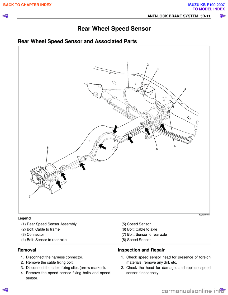
Rear Wheel Speed Sensor
Rear Wheel Speed Sensor and Associated Parts
420R300008
Legend
(1) Rear Speed Sensor Assembly
(2) Bolt: Cable to frame
(3) Connector
(4) Bolt: Sensor to rear axle
(5) Speed Sensor
(6) Bolt: Cable to axle
(7) Bolt: Sensor to rear axle
(8) Speed Sensor
Removal
1. Disconnect the harness connector.
2. Remove the cable fixing bolt.
3. Disconnect the cable fixing clips (arrow marked).
4. Remove the speed sensor fixing bolts and speed sensor.
Inspection and Repair
1. Check speed sensor head for presence of foreign
materials; remove any dirt, etc.
2. Check the head for damage, and replace speed sensor if necessary.
BACK TO CHAPTER INDEX
TO MODEL INDEX
ISUZU KB P190 2007