sensor ISUZU KB P190 2007 Workshop Manual Online
[x] Cancel search | Manufacturer: ISUZU, Model Year: 2007, Model line: KB P190, Model: ISUZU KB P190 2007Pages: 6020, PDF Size: 70.23 MB
Page 691 of 6020

5B-12 ANTI-LOCK BRAKE SYSTEM
3. Check speed sensor cable for short or open, and
replace with a new one if necessary. To check fo
r
cable short or open, bend or stretch the cable while
checking for continuity.
Installation
1. Install the speed sensor.
2. Tighten the sensor fixing bolts to the specified torque.
Torque: 8 N ⋅m (0.8 kgf ⋅m / 69 lb·in)
3. Connect the cable fixing clips (arrow marked).
4. Install the cable fixing bolts and tighten it to the specified torque.
Torque: 8 N ⋅m (0.8 kgf ⋅m / 69 lb·in)
5. Connect the harness connector.
BACK TO CHAPTER INDEX
TO MODEL INDEX
ISUZU KB P190 2007
Page 692 of 6020
ANTI-LOCK BRAKE SYSTEM 5B-13
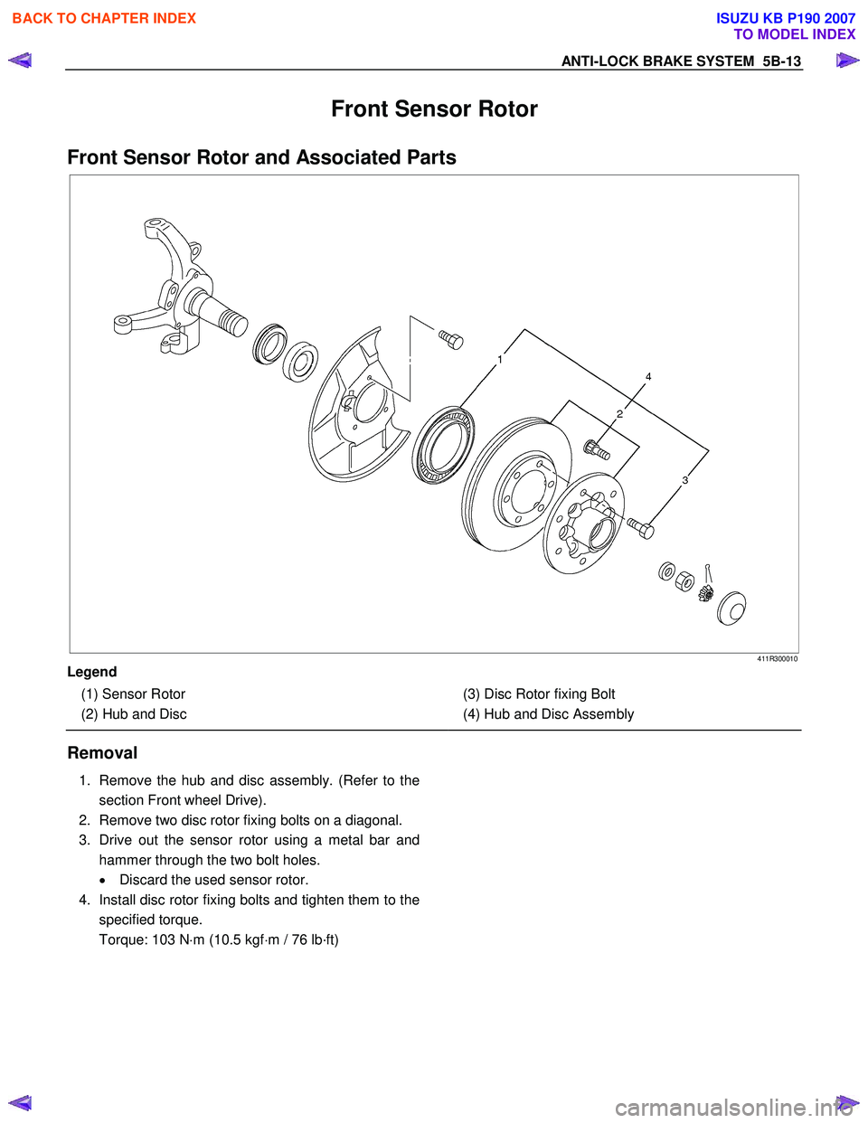
Front Sensor Rotor
Front Sensor Rotor and Associated Parts
411R300010
Legend
(1) Sensor Rotor
(2) Hub and Disc
(3) Disc Rotor fixing Bolt
(4) Hub and Disc Assembly
Removal
1. Remove the hub and disc assembly. (Refer to the
section Front wheel Drive).
2. Remove two disc rotor fixing bolts on a diagonal.
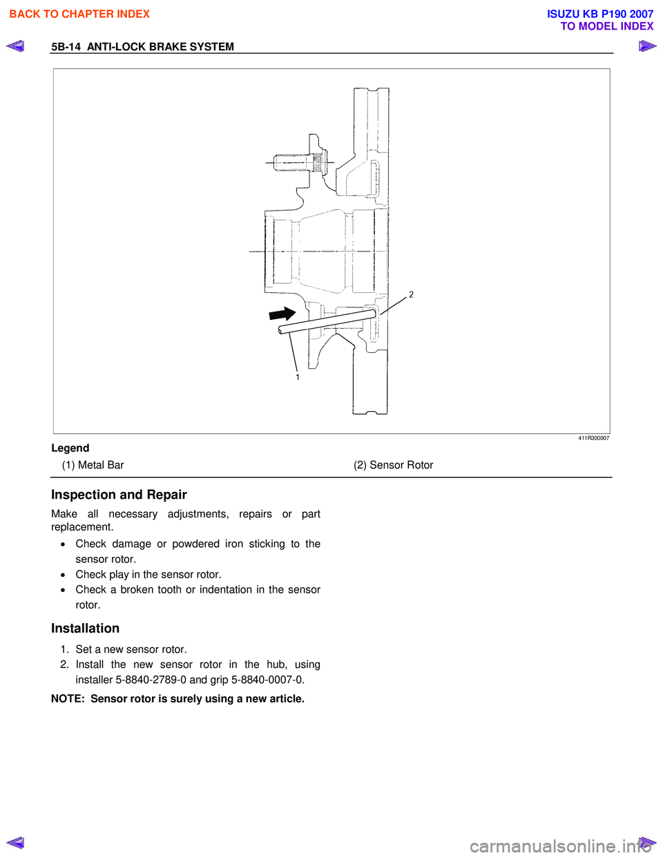
3. Drive out the sensor rotor using a metal bar and hammer through the two bolt holes.
• Discard the used sensor rotor.
4. Install disc rotor fixing bolts and tighten them to the specified torque.
Torque: 103 N ⋅m (10.5 kgf ⋅m / 76 lb·ft)
BACK TO CHAPTER INDEX
TO MODEL INDEX
ISUZU KB P190 2007
Page 693 of 6020
5B-14 ANTI-LOCK BRAKE SYSTEM
411R300007
Legend
(1) Metal Bar
(2) Sensor Rotor
Inspection and Repair
Make all necessary adjustments, repairs or part
replacement.
• Check damage or powdered iron sticking to the
sensor rotor.
• Check play in the sensor rotor.
• Check a broken tooth or indentation in the senso
r
rotor.
Installation
1. Set a new sensor rotor.
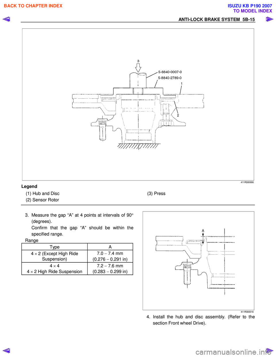
2. Install the new sensor rotor in the hub, using installer 5-8840-2789-0 and grip 5-8840-0007-0.
NOTE: Sensor rotor is surely using a new article.
BACK TO CHAPTER INDEX
TO MODEL INDEX
ISUZU KB P190 2007
Page 694 of 6020
ANTI-LOCK BRAKE SYSTEM 5B-15
411R300006
Legend
(1) Hub and Disc
(2) Sensor Rotor
(3) Press
3. Measure the gap “A” at 4 points at intervals of 90 °
(degrees).
Confirm that the gap “A” should be within the
specified range.
Range
Type A
4 × 2 (Except High Ride
Suspension) 7.0
− 7.4 mm
(0.276 − 0.291 in)
4 × 4
4 × 2 High Ride Suspension 7.2
− 7.6 mm
(0.283 − 0.299 in)
411R300016
4. Install the hub and disc assembly. (Refer to the
section Front wheel Drive).
BACK TO CHAPTER INDEX
TO MODEL INDEX
ISUZU KB P190 2007
Page 695 of 6020
5B-16 ANTI-LOCK BRAKE SYSTEM
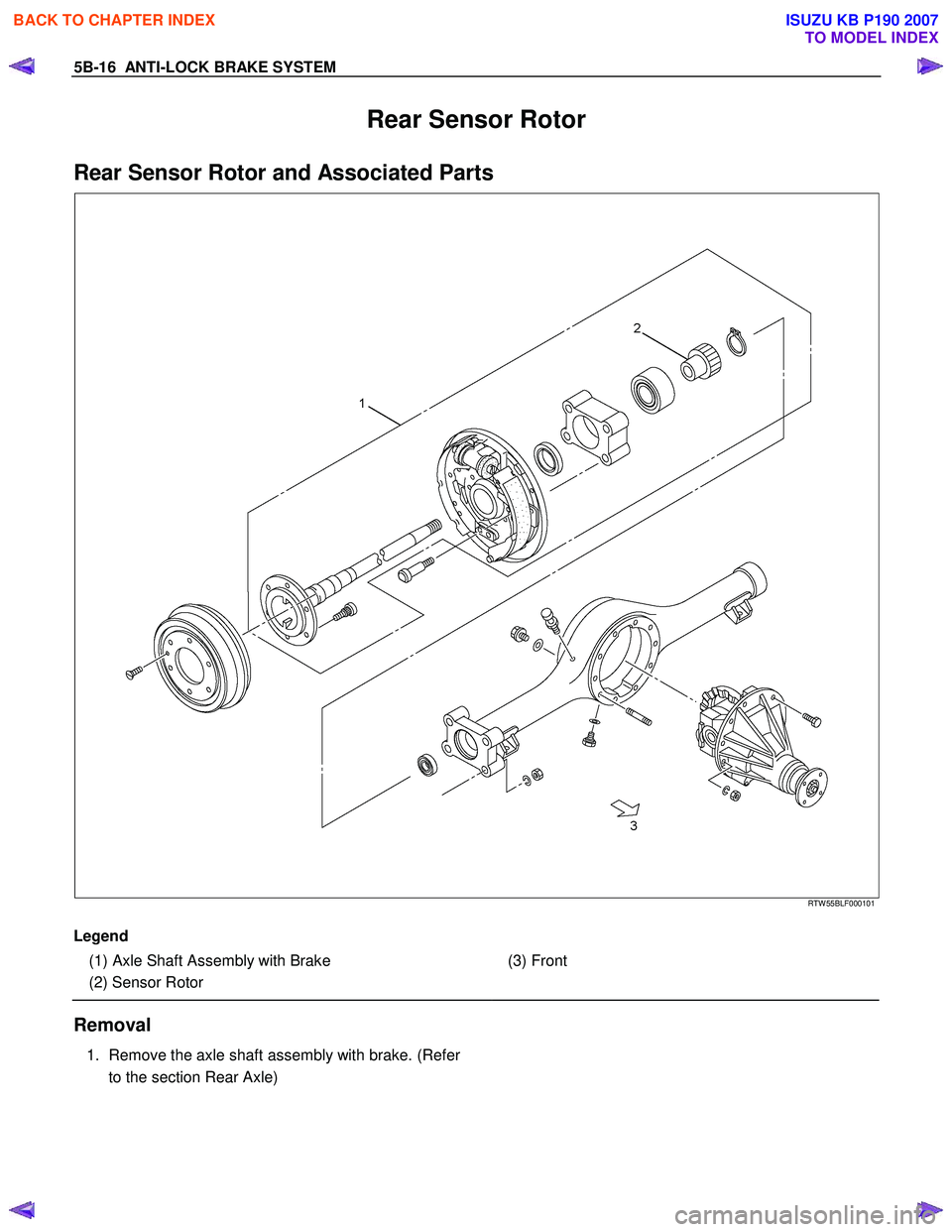
Rear Sensor Rotor
Rear Sensor Rotor and Associated Parts
RTW 55BLF000101
Legend
(1) Axle Shaft Assembly with Brake
(2) Sensor Rotor
(3) Front
Removal
1. Remove the axle shaft assembly with brake. (Refer
to the section Rear Axle)
BACK TO CHAPTER INDEX
TO MODEL INDEX
ISUZU KB P190 2007
Page 696 of 6020
ANTI-LOCK BRAKE SYSTEM 5B-17
RUW 55BMF000101
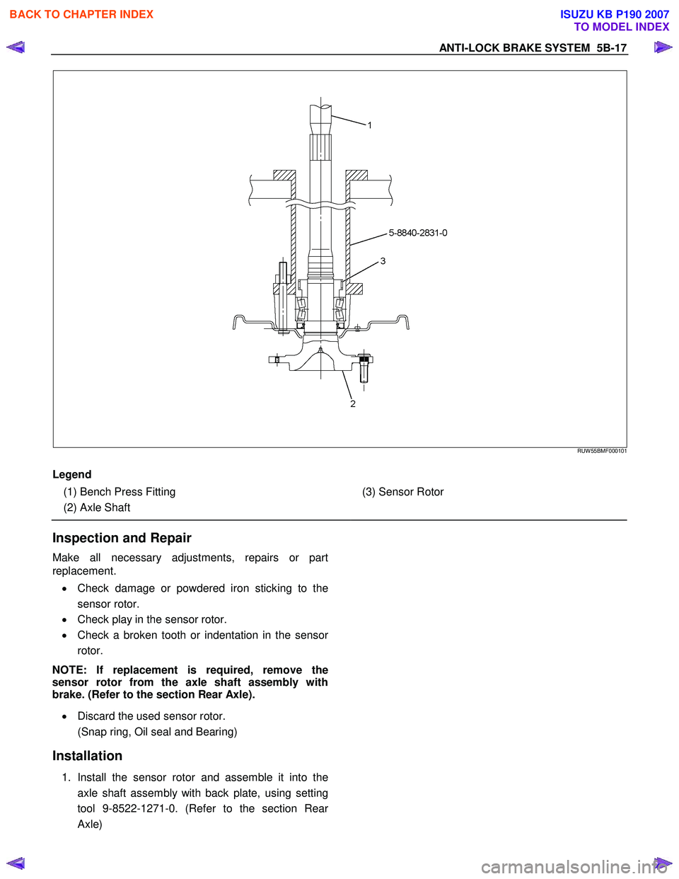
Legend
(1) Bench Press Fitting
(2) Axle Shaft
(3) Sensor Rotor
Inspection and Repair
Make all necessary adjustments, repairs or part
replacement.
• Check damage or powdered iron sticking to the
sensor rotor.
• Check play in the sensor rotor.
• Check a broken tooth or indentation in the senso
r
rotor.
NOTE: If replacement is required, remove the
sensor rotor from the axle shaft assembly with
brake. (Refer to the section Rear Axle).
• Discard the used sensor rotor.
(Snap ring, Oil seal and Bearing)
Installation
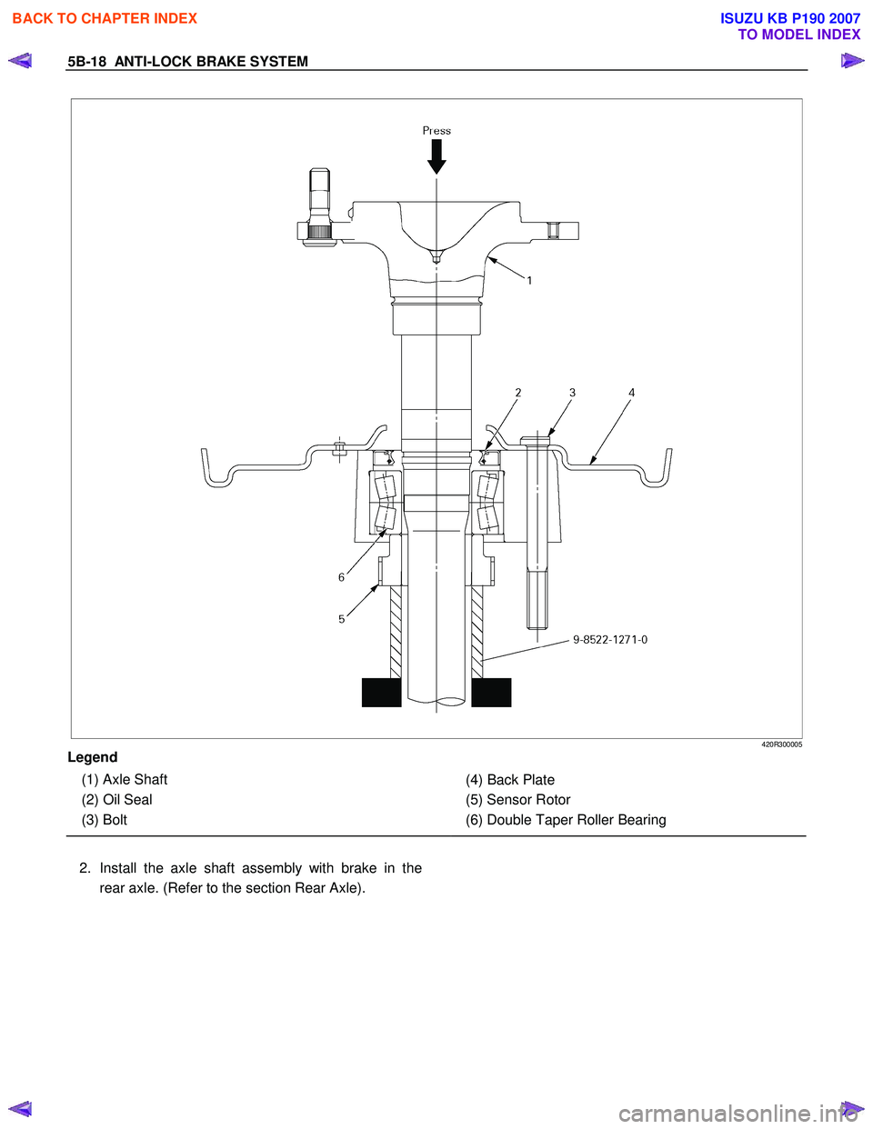
1. Install the sensor rotor and assemble it into the
axle shaft assembly with back plate, using setting
tool 9-8522-1271-0. (Refer to the section Rea
r
Axle)
BACK TO CHAPTER INDEX
TO MODEL INDEX
ISUZU KB P190 2007
Page 697 of 6020
5B-18 ANTI-LOCK BRAKE SYSTEM
420R300005
Legend
(1) Axle Shaft
(2) Oil Seal
(3) Bolt
(4) Back Plate
(5) Sensor Rotor
(6) Double Taper Roller Bearing
2. Install the axle shaft assembly with brake in the rear axle. (Refer to the section Rear Axle).
BACK TO CHAPTER INDEX
TO MODEL INDEX
ISUZU KB P190 2007
Page 698 of 6020

ANTI-LOCK BRAKE SYSTEM 5B-19
G-Sensor
G-Sensor and Associated Parts
This illustration is based on the RHD model
RTW 75BLF000101
Legend
(1) G-Sensor
(2) Nut
Removal
1. Remove the front floor console. (Refer to the section Floor Console)
2. Disconnect the connector.
3. Remove the nuts.
4. Take out the G-sensor.
Installation
1. Set the G-sensor.
2. Install the nut and tighten it to specified torque.
Torque: 8 N·m (0.8 kgf·m / 69 lb·in)
3. Connect the connector.
4. Install the front floor console. (Refer to the section Floor Console)
BACK TO CHAPTER INDEX
TO MODEL INDEX
ISUZU KB P190 2007
Page 843 of 6020
6A – 38 ENGINE MECHANICAL
6. Front propeller shaft (for 4x4 model)
Remove the spline yoke flange bolt at the transfer output
shaft.
Do not allow the spline yoke to fall away from the front
propeller shaft.
If the spline yoke should fall away from the front propeller
shaft, align the setting marks on the spline yoke and the
propeller shaft to reassemble the two marks. The setting
marks are punched circles approx. 3mm (0.12 in) in
diameter.
7. Clutch slave cylinder (for M/T model)
8. ATF pipe (for A/T model)
9 Shift control cable (for A/T model)
10. Transmission sensor harness Remove the vehicle speed sensor connector, inhibitor
switch connector (A/T), ATF temperature sensor
connector, back up light switch connector (M/T) from
transmission.
11. Breather hose (for A/T model)
12. Transmission shift lever (for M/T model) Remove the shift lever from the floor.
13. Transfer shift lever (for 4x4 model) Remove the shift lever from the floor.
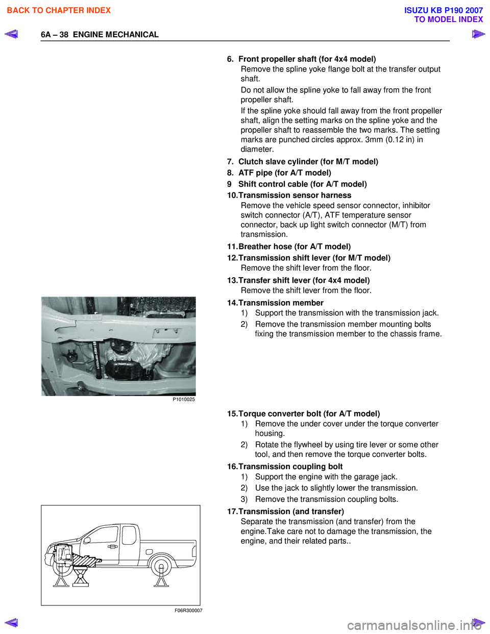
14. Transmission member 1) Support the transmission with the transmission jack.
2) Remove the transmission member mounting bolts fixing the transmission member to the chassis frame.
15. Torque converter bolt (for A/T model) 1) Remove the under cover under the torque converter housing.
2) Rotate the flywheel by using tire lever or some other tool, and then remove the torque converter bolts.
16. Transmission coupling bolt 1) Support the engine with the garage jack.
2) Use the jack to slightly lower the transmission.
3) Remove the transmission coupling bolts.
17. Transmission (and transfer) Separate the transmission (and transfer) from the
engine.Take care not to damage the transmission, the
engine, and their related parts..
F06R300007
P1010025
BACK TO CHAPTER INDEX
TO MODEL INDEX
ISUZU KB P190 2007
Page 844 of 6020
ENGINE MECHANICAL 6A – 39
18. Radiator 1) Drain the engine coolant.
2) Remove the reservoir hose.
3) Remove the upper and lower hose.
4) Remove the fan guide.
5) Remove the radiator.
19. Fan
P1010034
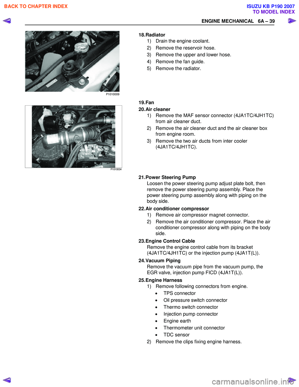
20. Air cleaner
1) Remove the MAF sensor connector (4JA1TC/4JH1TC) from air cleaner duct.
2) Remove the air cleaner duct and the air cleaner box from engine room.
3) Remove the two air ducts from inter cooler (4JA1TC/4JH1TC).
21. Power Steering Pump Loosen the power steering pump adjust plate bolt, then
remove the power steering pump assembly. Place the
power steering pump assembly along with piping on the
body side.
22. Air conditioner compressor 1) Remove air compressor magnet connector.
2) Remove the air conditioner compressor. Place the air conditioner compressor along with piping on the body
side.
23. Engine Control Cable Remove the engine control cable from its bracket
(4JA1TC/4JH1TC) or the injection pump (4JA1T(L)).
24. Vacuum Piping Remove the vacuum pipe from the vacuum pump, the
EGR valve, injection pump FICD (4JA1T(L)).
25. Engine Harness 1) Remove following connectors from engine.
• TPS connector
• Oil pressure switch connector
• Thermo switch connector
• Injection pump connector
• Engine earth
• Thermometer unit connector
• TDC sensor
2) Remove the clips fixing engine harness.
P1010009
BACK TO CHAPTER INDEX
TO MODEL INDEX
ISUZU KB P190 2007