check engine ISUZU KB P190 2007 Workshop Repair Manual
[x] Cancel search | Manufacturer: ISUZU, Model Year: 2007, Model line: KB P190, Model: ISUZU KB P190 2007Pages: 6020, PDF Size: 70.23 MB
Page 3576 of 6020
Engine Management – V6 – Service Operations Page 6C1-3–52
Oil Fouled (3)
W et, oily deposits with minor electrode wear possibly due to oil leaking past worn piston rings.
Breaking in a new or recently overhauled engine before the rings are fully seated may also result in this condition.
Deposit Fouling A (4)
Red brown, yellow and white coloured coatings on the insulator tip which are by-products of combustion. They come
from fuel and lubricating oil which generally contain additives. Most powdery deposits have no adverse effect on spark
plug operation, however, they may cause intermittent missing under severe operating conditions.
Deposit Fouling B (5)
Deposits similar to those identified in deposit fouling A (4). These are also by-products of combustion from fuel and
lubricating oil. Excessive valve stem clearances and / or defective intake valve seals allow too much oil to enter the
combustion chamber. The deposits will accumulate on the portion of the spark plug that projects into the chamber and
will be heaviest on the side facing the intake valve. If this condition is only detected in one or two cylinders, check the
valve stem seals.
Deposit Fouling C (6)
Most powdery deposits identified in deposit fouling A (4) have no adverse effect on the operation of the spark plug as
long as they remain powdery.
Under certain conditions of operation however, these deposits melt and form a shiny glaze coating on the insulator.
W hen hot, this acts as a good electrical conductor allowing the current to flow along the deposit instead of sparking
across the gap.
Detonation (7)
Commonly referred to as engine knock or pinging, detonation causes severe shocks inside the combustion chamber
causing damage to parts.
Pre-ignition (8)
Burnt or blistered insulator tip and badly eroded electrodes probably due to the excessive heat.
This is often caused by a cooling system blockage, sticking valves, improperly installed spark plugs or plugs that are the
wrong heat rating (too hot).
Sustained high speed with a heavy load can produce temperatures high enough to cause pre-ignition.
Heat Shock Failure (9)
A rapid increase in spark plug tip temperature under severe operating conditions can cause heat shock and result in
fractured insulators. This is a common cause of broken and cracked insulator tips.
Insufficient Installation Torque (10)
Poor contact between the spark plug and the cylinder head seat.
The lack of proper heat transfer that results from poor seat contact causes overheating of the spark plug. In many cases,
severe damage occurs. Dirty threads in the cylinder head can cause the plug to seize before it is seated.
Ensure the cylinder head and spark plug threads are free of deposits, burrs and scale before installation.
BACK TO CHAPTER INDEX
TO MODEL INDEX
ISUZU KB P190 2007
Page 3577 of 6020
Engine Management – V6 – Service Operations Page 6C1-3–53
Reinstall
Reinstallation of the spark plug is the reverse of the removal procedure, noting the following:
• Discard the spark plug if it has been
dropped.
• Do not use anti-seize compound or similar
lubricant on the spark plug threads.
1 Using a suitably sized rubber tube attached to the spark plug terminal post, hand start each spark plug into the cylinder head thread.
Failure to tighten a spark plug to the correct
torque specification may result in premature
spark plug failure, and / or engine damage.
2 Tighten the spark plug/s to the correct torque specification. Spark plug torque specification ...............16.0 – 20.0 Nm
3 Road test the vehicle and check for correct operation.
2.23 Throttle Body Assembly
Handling Precautions
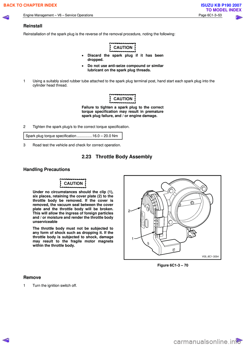
Under no circumstances should the clip (1),
six places, retaining the cover plate (2) to the
throttle body be removed. If the cover is
removed, the vacuum seal between the cover
plate and the throttle body will be broken.
This will allow the ingress of foreign particles
and / or moisture and render the throttle body
unserviceable
The throttle body must not be subjected to
any form of shock such as dropping it. If the
throttle body is subjected to shock, damage
may result to the fragile motor magnets
within the throttle body.
Figure 6C1-3 – 70
Remove
1 Turn the ignition switch off.
BACK TO CHAPTER INDEX
TO MODEL INDEX
ISUZU KB P190 2007
Page 3579 of 6020
Engine Management – V6 – Service Operations Page 6C1-3–55
Inspect
The following throttle body inspection procedure may be carried out with the throttle body installed on the vehicle. Prior to
performing a throttle body on-vehicle inspection:
• Turn the ignition switch off.
• Disconnect the throttle body wiring harness connector. Refer to Remove in this Section.
• Remove the air intake duct, refer to 2.16 Intake Air Duct Assembly.
To avoid serious personal injury, never
attempt to rotate the throttle plate manually
whilst the throttle body harness connector is
connected to the throttle body.
1 Fully open the throttle plate by hand and inspect the throttle body bore and throttle plate for any deposits.
When cleaning / inspecting the throttle body:
• Do not subject the throttle body assembly
to an immersion cleaner or a strong
solvent. Damage to the throttle position
sensor and / or sealed throttle shaft
bearings will result.
• Never use a wire brush or scraper to clean
the throttle body. A wire brush or sharp
tool may damage the throttle body
components.
2 Use a clean shop towel and a spray type hydro-carbon cleaner to clean the throttle body bore and throttle plate. If necessary, use a parts cleaning brush to remove heavy deposits.
3 Inspect the throttle body for a binding throttle plate by fully opening and closing the throttle plate by hand. It should open and close smoothly.
4 Inspect the throttle body for a bent or damaged throttle plate, cracks, corrosion, or distortion in the throttle body housing.
NOTE
The throttle body contains no serviceable parts
and should not be disassembled. If the throttle
body is damaged it must be replaced as an
assembly.
5 If the throttle body is affected by any of the above conditions, it must be replaced.
6 If an on-vehicle throttle body inspection was performed, perform the following:
• Reinstall the air intake duct, refer to 2.16 Intake Air Duct Assembly.
• Reconnect the throttle body wiring harness connector, refer to Reinstall in this Section.
• Road test the vehicle and check for correct operation, taking particular note that no air leaks are evident.
Reinstall
Reinstallation of the throttle body assembly is the reverse of the removal procedure, noting the following:
1 Ensure the throttle body and upper intake manifold mating surfaces are clean and free of foreign material.
2 Install a new throttle body to upper intake manifold gasket.
BACK TO CHAPTER INDEX
TO MODEL INDEX
ISUZU KB P190 2007
Page 3580 of 6020
Engine Management – V6 – Service Operations Page 6C1-3–56
3 Reinstall the throttle body bolts and tighten to the correct torque specification.
Throttle body assembly attaching bolt
torque specification ...................................8.0 – 12.0 Nm
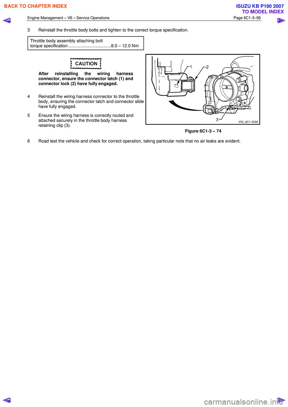
After reinstalling the wiring harness
connector, ensure the connector latch (1) and
connector lock (2) have fully engaged.
4 Reinstall the wiring harness connector to the throttle body, ensuring the connector latch and connector slide
have fully engaged.
5 Ensure the wiring harness is correctly routed and attached securely in the throttle body harness
retaining clip (3).
Figure 6C1-3 – 74
6 Road test the vehicle and check for correct operation, taking particular note that no air leaks are evident.
BACK TO CHAPTER INDEX
TO MODEL INDEX
ISUZU KB P190 2007
Page 3586 of 6020
Engine Management – V6 – Service Operations Page 6C1-3–62
6 Special Tools
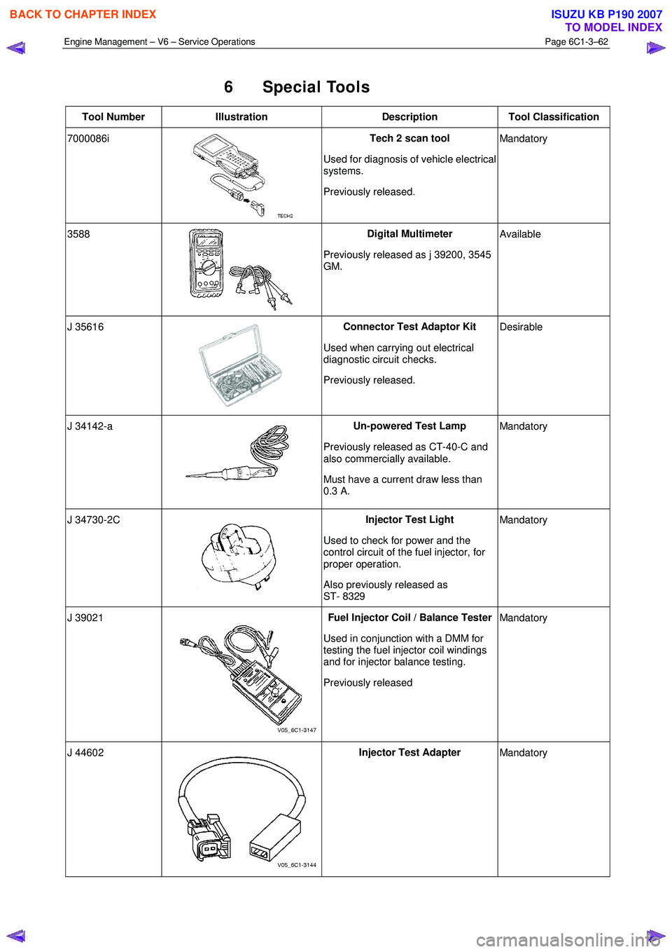
Tool Number Illustration Description Tool Classification
7000086i
Tech 2 scan tool
Used for diagnosis of vehicle electrical
systems.
Previously released. Mandatory
3588
Digital Multimeter
Previously released as j 39200, 3545
GM. Available
J 35616
Connector Test Adaptor Kit
Used when carrying out electrical
diagnostic circuit checks.
Previously released. Desirable
J 34142-a
Un-powered Test Lamp
Previously released as CT-40-C and
also commercially available.
Must have a current draw less than
0.3 A. Mandatory
J 34730-2C
Injector Test Light
Used to check for power and the
control circuit of the fuel injector, for
proper operation.
Also previously released as
ST- 8329 Mandatory
J 39021 Fuel Injector Coil / Balance Tester
Used in conjunction with a DMM for
testing the fuel injector coil windings
and for injector balance testing.
Previously released Mandatory
J 44602 Injector Test Adapter
Mandatory
BACK TO CHAPTER INDEX
TO MODEL INDEX
ISUZU KB P190 2007
Page 3594 of 6020
Charging System – V6 Page 6D1-1-7
2 Diagnosis
2.1 Diagnostic General Information
Basic Diagnostic Tools Required
Use of incorrect electrical circuit diagnostic
tools when performing the generator
diagnostic procedures could result in
incorrect diagnostic results or damage to
components.
The following electrical circuit testing tools are required to perform the diagnostic procedures detailed in this Section:
• digital multimeter with 10 mega ohms impedance, and
• connector test adapter kit Tool No. KM609.
For further information on the use of these tools, refer to 8A Electrical Body and Chassis.
2.2 Tech 2 Data List
The Tech 2 displays the status of certain charging system parameters.
To view the data list:
1 Connect Tech 2 to the DLC.
2 On Tech 2 select: Engine / V6 Engine / Data Display / Data List / Electrical/Theft Data .
Tech 2 Parameter Units Displayed Typical Display Values
Alternator L Terminal D Percentage Various
2.3 Diagnostic Systems Check
Step Action Yes No
1 1 Connect Tech 2 to the DLC.
2 Ignition ON, engine OFF.
3 On Tech 2 select: Engine / V6 Engine / Diagnostic Trouble codes / Read
DTC’s.
Are there any set DTC’s? Go to the
appropriate DTC table in 6C1-2 Engine
Management – V6 – Diagnostics. Refer to 2.5
Charging
System Inoperative / Malfunctioning
Reference to following information will assist when diagnosing charging circuit faults:
• for battery testing, refer to 6D1-3 Battery – V6,
• for wiring diagram details, refer to Figure 6D1-1 2, and
• for electrical component locations, refer to 8A Electrical Body and Chassis.
BACK TO CHAPTER INDEX
TO MODEL INDEX
ISUZU KB P190 2007
Page 3597 of 6020
Charging System – V6 Page 6D1-1-10
3 Minor Service Operations
3.1 Safety Precautions
Observe the following precautions. Failure to observe these precautions will result in serious damage to the generator.
• Only use the generator and voltage regulator in a negative ground system.
• Always refer to 1.2 W ARNING, CAUTION and NOTES before disconnecting the battery.
• W hen installing a battery, fit the positive (+) cable to the battery before fitting the negative cable.
• W hen a slave battery is used for starting purposes, ensure that both batteries are connected in parallel. That is,
positive terminals connected and negative terminals connected.
• Only use jumper leads that have surge protection.
• Disconnect both battery cables when charging the battery. This isolates the generator from the battery and from
the external charging equipment.
• Do not operate the generator within an open circuit or without a battery in the circuit.
• Do not disconnect the battery while the generator is running.
• Do not attempt to polarise the generator.
• Do not connect generator connector E-4 pin 1 to 12 V (the battery or ignition circuits).
• Some battery powered timing lights can produce high transient voltages when connected or disconnected.
Only disconnect or connect timing lights when the engine is switched off.
Ensure the generator connector E-4 pin 1 has
a maximum sinking current of 50mA.
3.2 Maintenance
Regular Checks
Check the following at regular intervals:
• generator terminals – for corrosion and loose connections,
• wiring – for continuity and damaged insulation,
• mounting bolts – for tightness,
• drive belt – for alignment and wear, and
• drive pulley – for damage and warping.
NOTE
The drive-belt adjustment for the engine
ancillaries (i.e. generator and water pump) is
provided by a spring-loaded tensioner. Therefore,
the drive belt does not require manual
adjustment.
Lubrication
High tolerance bearings are used in this generator. If the bearings are removed during the generator disassembly, new
bearings must be installed to restore the generator to original specification. The ball bearings supporting the rotor shaft
are pre-lubricated and sealed. Do not attempt to lubricate these during servicing.
BACK TO CHAPTER INDEX
TO MODEL INDEX
ISUZU KB P190 2007
Page 3598 of 6020
Charging System – V6 Page 6D1-1-11
3.3 On-vehicle Testing
Generator On-vehicle Checks
Prerequisites
Before testing the generator output, ensure that:
• all generator circuit connections are clean and tight,
• the generator is always connected to the battery during testing (to prevent damage to the diodes),
• the battery is fully charged, and
• the specific gravity does not vary more than 0.025 between cells. (It is recommended the average specific gravity
is 1.260 or higher). Refer to 6D1-3 Battery – V6.
Carry out a load test on the battery to determine its ability to supply and accept current. This is a good indicator of the
general condition of the battery. For details of battery testing, refer to 6D1-3 Battery – V6.
Inspect the drive belt and tensioner markings to determine if the drive belt is within operating limits. Replace the belt if it
is excessively worn or outside the operating range of the tensioner.
For further details, refer to 6A1 Engine Mechanical – V6.
Generator Test
Regulating Voltage Test
NOTE
Leave the generator E-4 wiring harness
connector connected, as it provides initial field
excitation.
1 Ensure the ignition switch is in the OFF position and all electrical equipment is turned off.
Refer to 1.2 WARNING, CAUTION and
NOTES before disconnecting the battery.
2 Disconnect the battery ground cable P-5 at the battery.
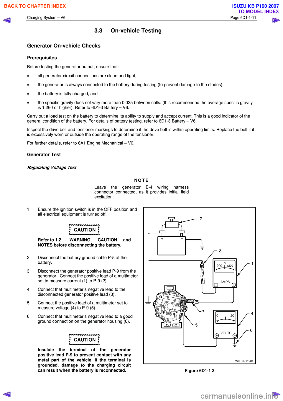
3 Disconnect the generator positive lead P-9 from the generator . Connect the positive lead of a multimeter
set to measure current (1) to P-9 (2).
4 Connect that multimeter’s negative lead to the disconnected generator positive lead (3).
5 Connect the positive lead of a multimeter set to measure voltage (4) to P-9 (5).
6 Connect that multimeter’s negative lead to a good ground connection on the generator housing (6).
Insulate the terminal of the generator
positive lead P-9 to prevent contact with any
metal part of the vehicle. If the terminal is
grounded, damage to the charging circuit
can result when the battery is reconnected.
Figure 6D1-1 3
BACK TO CHAPTER INDEX
TO MODEL INDEX
ISUZU KB P190 2007
Page 3599 of 6020
Charging System – V6 Page 6D1-1-12
7 Reconnect the battery ground cable P-5.
8 Fit a loading device (7) across the battery terminals, e.g. an adjustable carbon pile.
The loading device must have a minimum
power consumption of 1000 W.
9 Record the voltage reading before starting the engine. (This reading should increase when the engine is running, indicating generator output.).
10 Start the engine.
11 Increase the engine speed to the value outlined in the chart below.
12 Using the reading from the multimeter set to measure current, adjust the loading device to apply a load within the range outlined in the chart below.
13 Using the multimeter set to measure voltage, check the generator output voltage against the specification.
Engine RPM ........................................................... 1300
Load ................................................................ 5.0 – 10 A
Output Voltage ........................................... 13.8 – 15.4 V
Load Regulation Test
NOTE
The decrease in the voltage recorded during this
test should not exceed 0.5 V from the readings
obtained for the Regulating Voltage Test. If the
decrease in the regulating voltage is greater than
0.5 V, the regulator is defective. Replace the
regulator.
14 Increase the engine speed to the value outlined in the chart below.
15 Using the reading from the multimeter set to measure current, adjust the loading device to apply a load of about 90% of the generator’s full output.
16 Using the multimeter set to measure voltage, check the generator output voltage against the specification.
Engine RPM............................................................ 1900
Load ......................................................................... 90 A
Output Voltage ........................................... 13.8 – 15.4 V
Full Load Output Test
Keep the time for this test to a minimum to
avoid undue heating and high engine speeds.
17 Increase the engine speed to the value outlined in the chart below .
18 Using the reading from the multimeter set to measure voltage, adjust the loading device to increase the load until the generator output voltage drops to 13.5 V. Full generator output, outlined in the chart below, is required.
19 Record the current reading displayed on the multimeter set to measure current.
BACK TO CHAPTER INDEX
TO MODEL INDEX
ISUZU KB P190 2007
Page 3601 of 6020
Charging System – V6 Page 6D1-1-14
8 Connect the positive lead of a multimeter set to measure voltage to the battery negative post.
9 Connect the negative lead of the multimeter to the generator housing.
9 Increase the engine speed to approximately 2500 r.p.m.
10 Record the voltage reading.
11 Reduce the engine speed to idle.
12 Check the two readings. If the readings exceed 0.3 V, there is a high resistance in the charging circuit.
13 Trace the cause and correct the problem, refer to 8A Electrical Body and Chassis.
BACK TO CHAPTER INDEX
TO MODEL INDEX
ISUZU KB P190 2007