check engine ISUZU KB P190 2007 Workshop Repair Manual
[x] Cancel search | Manufacturer: ISUZU, Model Year: 2007, Model line: KB P190, Model: ISUZU KB P190 2007Pages: 6020, PDF Size: 70.23 MB
Page 3560 of 6020
Engine Management – V6 – Service Operations Page 6C1-3–36
Remove
1 Turn the ignition switch off.
2 Raise the vehicle and support on safety stands, refer to 0A General Information for location of the jacking points.
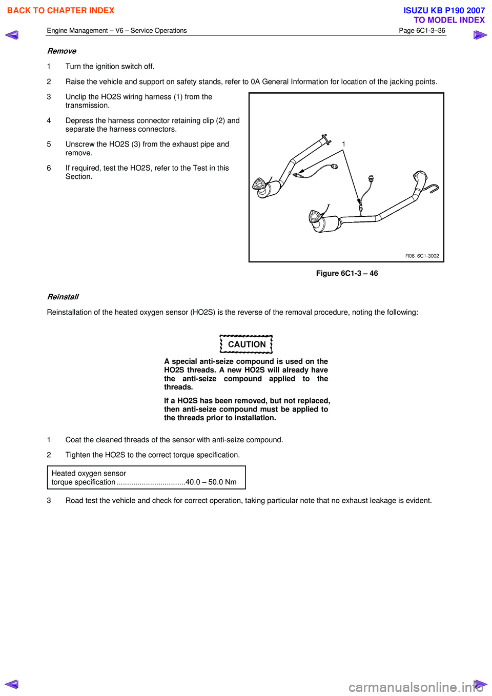
3 Unclip the HO2S wiring harness (1) from the transmission.
4 Depress the harness connector retaining clip (2) and separate the harness connectors.
5 Unscrew the HO2S (3) from the exhaust pipe and remove.
6 If required, test the HO2S, refer to the Test in this Section.
Figure 6C1-3 – 46
Reinstall
Reinstallation of the heated oxygen sensor (HO2S) is the reverse of the removal procedure, noting the following:
A special anti-seize compound is used on the
HO2S threads. A new HO2S will already have
the anti-seize compound applied to the
threads.
If a HO2S has been removed, but not replaced,
then anti-seize compound must be applied to
the threads prior to installation.
1 Coat the cleaned threads of the sensor with anti-seize compound.
2 Tighten the HO2S to the correct torque specification.
Heated oxygen sensor
torque specification .................................40.0 – 50.0 Nm
3 Road test the vehicle and check for correct operation, taking particular note that no exhaust leakage is evident.
BACK TO CHAPTER INDEX
TO MODEL INDEX
ISUZU KB P190 2007
Page 3561 of 6020
Engine Management – V6 – Service Operations Page 6C1-3–37
Test
Under no circumstances should battery
voltage be applied to the heated oxygen
sensor (HO2S) heater.
To prevent component damage use connector
test adaptor kit J 35616-A.
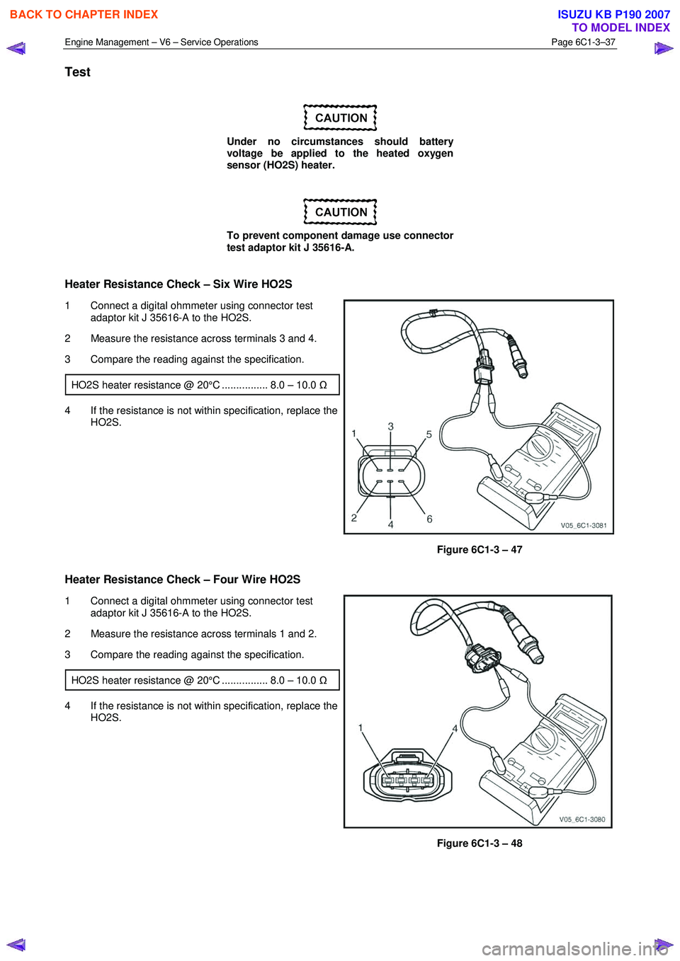
Heater Resistance Check – Six Wire HO2S
1 Connect a digital ohmmeter using connector test adaptor kit J 35616-A to the HO2S.
2 Measure the resistance across terminals 3 and 4.
3 Compare the reading against the specification.
HO2S heater resistance @ 20°C ................ 8.0 – 10.0 Ω
4 If the resistance is not within specification, replace the
HO2S.
Figure 6C1-3 – 47
Heater Resistance Check – Four Wire HO2S
1 Connect a digital ohmmeter using connector test
adaptor kit J 35616-A to the HO2S.
2 Measure the resistance across terminals 1 and 2.
3 Compare the reading against the specification.
HO2S heater resistance @ 20°C ................ 8.0 – 10.0 Ω
4 If the resistance is not within specification, replace the
HO2S.
Figure 6C1-3 – 48
BACK TO CHAPTER INDEX
TO MODEL INDEX
ISUZU KB P190 2007
Page 3563 of 6020
Engine Management – V6 – Service Operations Page 6C1-3–39
Disassemble
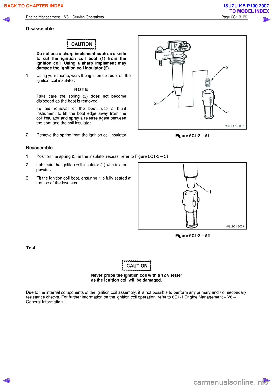
Do not use a sharp implement such as a knife
to cut the ignition coil boot (1) from the
ignition coil. Using a sharp implement may
damage the ignition coil insulator (2).
1 Using your thumb, work the ignition coil boot off the ignition coil insulator.
NOTE
Take care the spring (3) does not become
dislodged as the boot is removed.
To aid removal of the boot, use a blunt
instrument to lift the boot edge away from the
coil insulator and spray a release agent between
the boot and the coil insulator.
2 Remove the spring from the ignition coil insulator.
Figure 6C1-3 – 51
Reassemble
1 Position the spring (3) in the insulator recess, refer to Figure 6C1-3 – 51.
2 Lubricate the ignition coil insulator (1) with talcum powder.
3 Fit the ignition coil boot, ensuring it is fully seated at the top of the insulator.
Figure 6C1-3 – 52
Test
Never probe the ignition coil with a 12 V tester
as the ignition coil will be damaged.
Due to the internal components of the ignition coil assembly, it is not possible to perform any primary and / or secondary
resistance checks. For further information on the ignition coil operation, refer to 6C1-1 Engine Management – V6 –
General Information.
BACK TO CHAPTER INDEX
TO MODEL INDEX
ISUZU KB P190 2007
Page 3564 of 6020
Engine Management – V6 – Service Operations Page 6C1-3–40
Reinstall
Reinstallation of the ignition coil is the reverse of the removal procedure, noting the following:
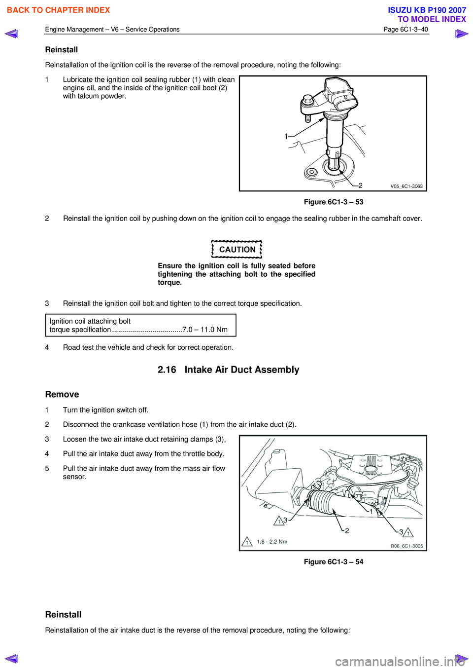
1 Lubricate the ignition coil sealing rubber (1) with clean engine oil, and the inside of the ignition coil boot (2)
with talcum powder.
Figure 6C1-3 – 53
2 Reinstall the ignition coil by pushing down on the ignition coil to engage the sealing rubber in the camshaft cover.
Ensure the ignition coil is fully seated before
tightening the attaching bolt to the specified
torque.
3 Reinstall the ignition coil bolt and tighten to the correct torque specification. Ignition coil attaching bolt
torque specification ...................................7.0 – 11.0 Nm
4 Road test the vehicle and check for correct operation.
2.16 Intake Air Duct Assembly
Remove
1 Turn the ignition switch off.
2 Disconnect the crankcase ventilation hose (1) from the air intake duct (2).
3 Loosen the two air intake duct retaining clamps (3),
4 Pull the air intake duct away from the throttle body.
5 Pull the air intake duct away from the mass air flow sensor.
Figure 6C1-3 – 54
Reinstall
Reinstallation of the air intake duct is the reverse of the removal procedure, noting the following:
BACK TO CHAPTER INDEX
TO MODEL INDEX
ISUZU KB P190 2007
Page 3565 of 6020
Engine Management – V6 – Service Operations Page 6C1-3–41
Ensure the air intake duct sealing rubber is
correctly positioned on the throttle body.
Failure to do this may result in engine
damage due to unfiltered air entering the
engine intake system.
1 Reinstall the air intake duct and tighten the retaining clamps to the correct torque specification. Air intake duct retaining clamp
torque specification .....................................1.8 – 2.2 Nm
2 Road test the vehicle and check for correct operation, taking particular note that no air leaks are evident.
2.17 Intake Air Temperature Sensor
The intake air temperature (IAT) sensor is part of the mass air flow (MAF) sensor assembly, refer to 2.20 Mass Air
Flow Sensor for the replacement procedure.
Test
To prevent component damage use connector
test adaptor kit J 35616-A.
Resistance Check
Do not use a high temperature heat gun as
damage to the MAF sensor will result.
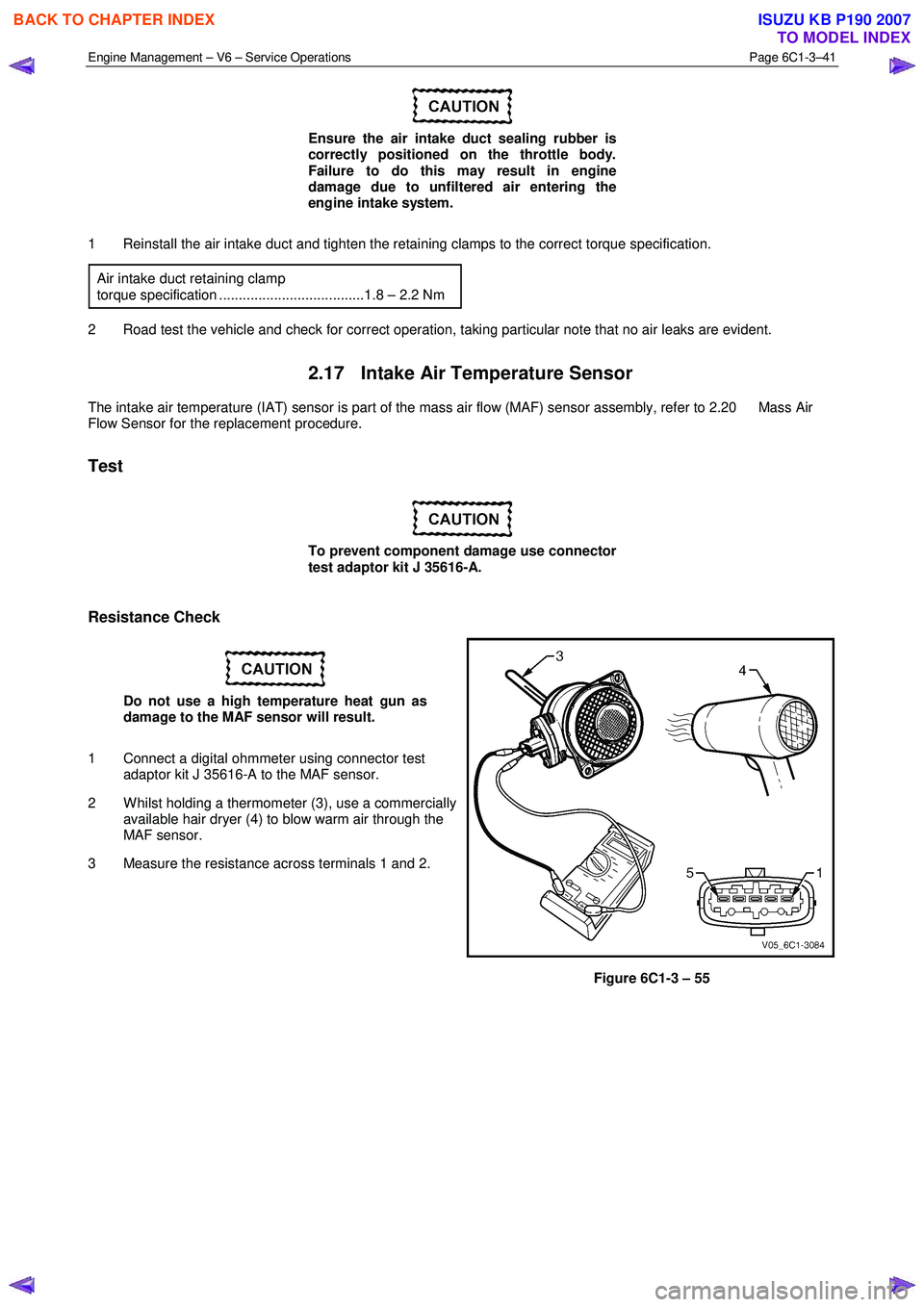
1 Connect a digital ohmmeter using connector test adaptor kit J 35616-A to the MAF sensor.
2 W hilst holding a thermometer (3), use a commercially available hair dryer (4) to blow warm air through the
MAF sensor.
3 Measure the resistance across terminals 1 and 2.
Figure 6C1-3 – 55
BACK TO CHAPTER INDEX
TO MODEL INDEX
ISUZU KB P190 2007
Page 3567 of 6020
Engine Management – V6 – Service Operations Page 6C1-3–43
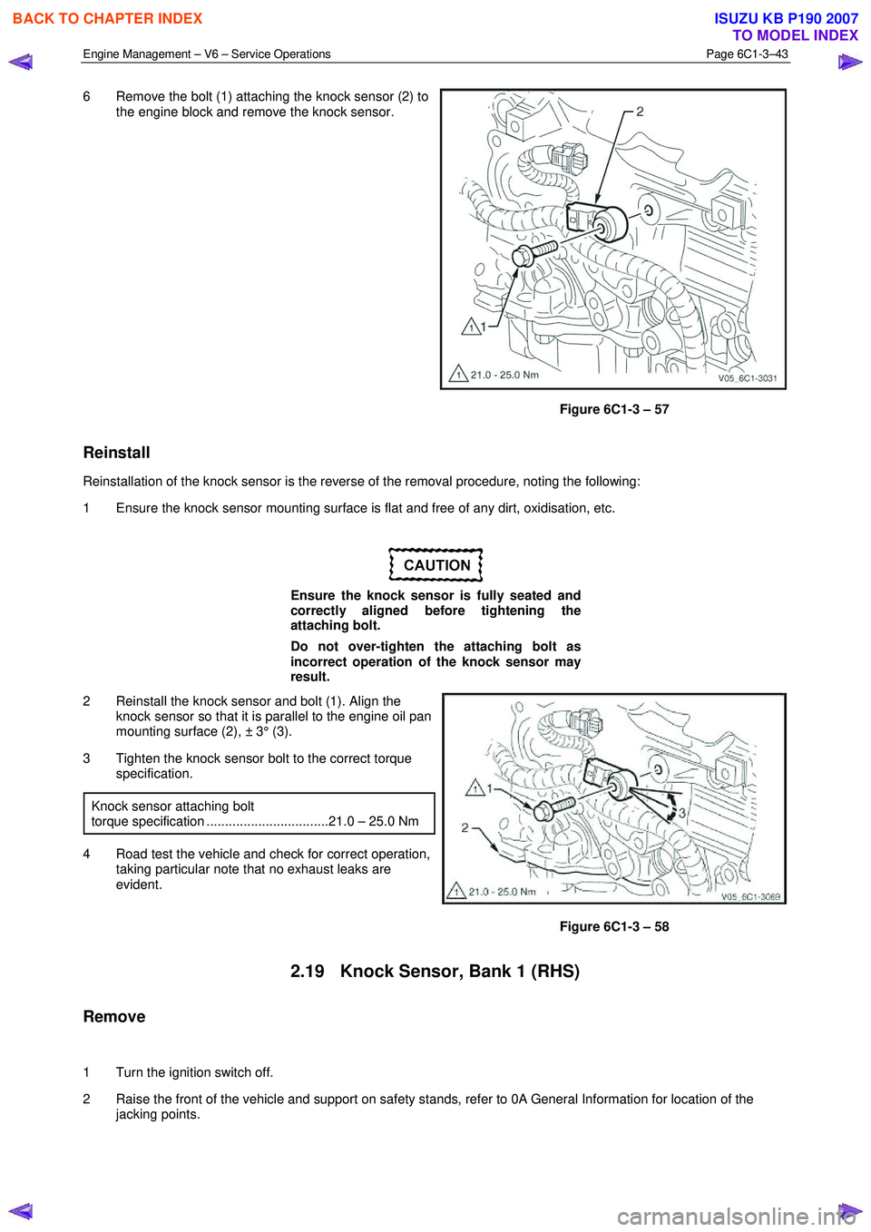
6 Remove the bolt (1) attaching the knock sensor (2) to
the engine block and remove the knock sensor.
Figure 6C1-3 – 57
Reinstall
Reinstallation of the knock sensor is the reverse of the removal procedure, noting the following:
1 Ensure the knock sensor mounting surface is flat and free of any dirt, oxidisation, etc.
Ensure the knock sensor is fully seated and
correctly aligned before tightening the
attaching bolt.
Do not over-tighten the attaching bolt as
incorrect operation of the knock sensor may
result.
2 Reinstall the knock sensor and bolt (1). Align the knock sensor so that it is parallel to the engine oil pan
mounting surface (2), ± 3° (3).
3 Tighten the knock sensor bolt to the correct torque specification.
Knock sensor attaching bolt
torque specification .................................21.0 – 25.0 Nm
4 Road test the vehicle and check for correct operation, taking particular note that no exhaust leaks are
evident.
Figure 6C1-3 – 58
2.19 Knock Sensor, Bank 1 (RHS)
Remove
1 Turn the ignition switch off.
2 Raise the front of the vehicle and support on safety stands, refer to 0A General Information for location of the jacking points.
BACK TO CHAPTER INDEX
TO MODEL INDEX
ISUZU KB P190 2007
Page 3569 of 6020
Engine Management – V6 – Service Operations Page 6C1-3–45
Ensure the knock sensor is fully seated
before tightening the attaching bolt.
Do not over-tighten the attaching bolt as
incorrect operation of the knock sensor may
result.
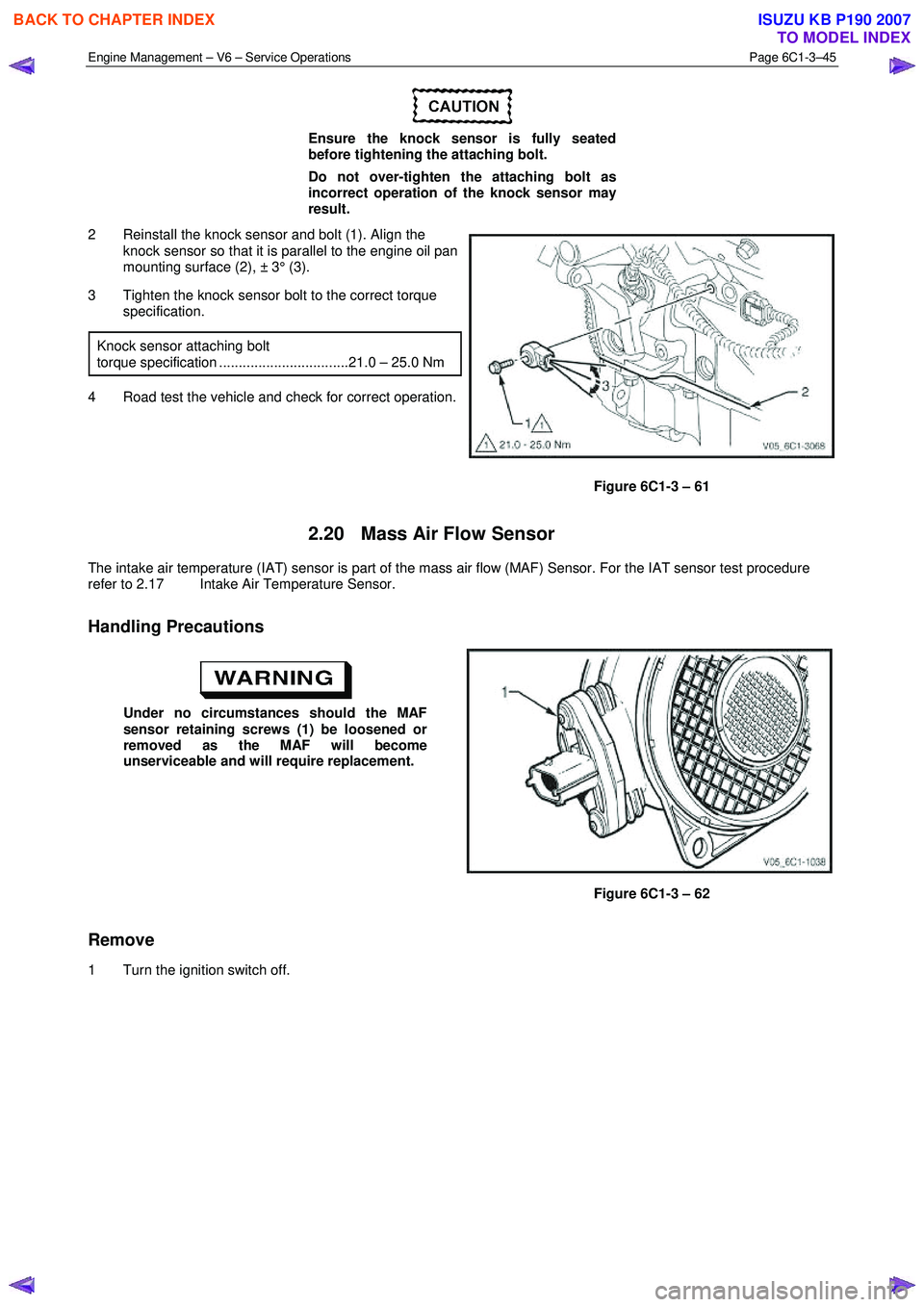
2 Reinstall the knock sensor and bolt (1). Align the knock sensor so that it is parallel to the engine oil pan
mounting surface (2), ± 3° (3).
3 Tighten the knock sensor bolt to the correct torque specification.
Knock sensor attaching bolt
torque specification .................................21.0 – 25.0 Nm
4 Road test the vehicle and check for correct operation.
Figure 6C1-3 – 61
2.20 Mass Air Flow Sensor
The intake air temperature (IAT) sensor is part of the mass air flow (MAF) Sensor. For the IAT sensor test procedure
refer to 2.17 Intake Air Temperature Sensor.
Handling Precautions
Under no circumstances should the MAF
sensor retaining screws (1) be loosened or
removed as the MAF will become
unserviceable and will require replacement.
Figure 6C1-3 – 62
Remove
1 Turn the ignition switch off.
BACK TO CHAPTER INDEX
TO MODEL INDEX
ISUZU KB P190 2007
Page 3570 of 6020
Engine Management – V6 – Service Operations Page 6C1-3–46
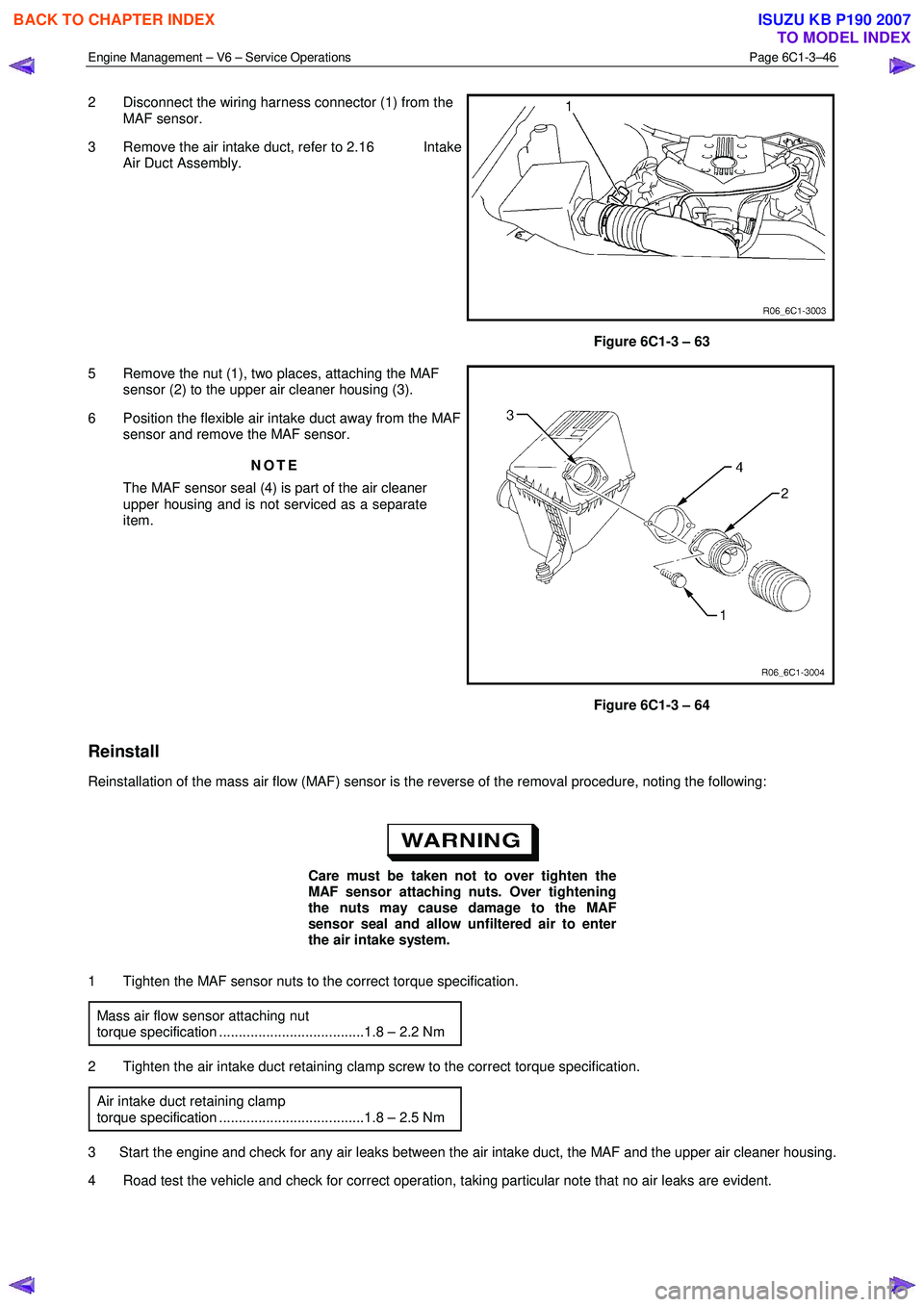
2 Disconnect the wiring harness connector (1) from the
MAF sensor.
3 Remove the air intake duct, refer to 2.16 Intake Air Duct Assembly.
Figure 6C1-3 – 63
5 Remove the nut (1), two places, attaching the MAF sensor (2) to the upper air cleaner housing (3).
6 Position the flexible air intake duct away from the MAF sensor and remove the MAF sensor.
NOTE
The MAF sensor seal (4) is part of the air cleaner
upper housing and is not serviced as a separate
item.
Figure 6C1-3 – 64
Reinstall
Reinstallation of the mass air flow (MAF) sensor is the reverse of the removal procedure, noting the following:
Care must be taken not to over tighten the
MAF sensor attaching nuts. Over tightening
the nuts may cause damage to the MAF
sensor seal and allow unfiltered air to enter
the air intake system.
1 Tighten the MAF sensor nuts to the correct torque specification. Mass air flow sensor attaching nut
torque specification .....................................1.8 – 2.2 Nm
2 Tighten the air intake duct retaining clamp screw to the correct torque specification. Air intake duct retaining clamp
torque specification .....................................1.8 – 2.5 Nm
3 Start the engine and check for any air leaks between the air intake duct, the MAF and the upper air cleaner housing.
4 Road test the vehicle and check for correct operation, taking particular note that no air leaks are evident.
BACK TO CHAPTER INDEX
TO MODEL INDEX
ISUZU KB P190 2007
Page 3571 of 6020
Engine Management – V6 – Service Operations Page 6C1-3–47
2.21 Schrader Valve – Fuel Pressure Gauge
Connection Point
If the Schrader valve is to be removed but not
replaced immediately, it is advisable to
disconnect the battery to avoid possible fuel
discharge if an accidental attempt is made to
start the engine.
Disconnection of the battery affects vehicle
electronic systems. Refer to 6D1-3 Battery –
V6 before disconnecting the battery.
Remove
1 Depressurise the fuel system, refer to 6C Fuel System - V6.
2 Turn the ignition off.
A small amount of fuel may be released when
servicing the fuel pressure test point. To
reduce the chance of personal injury, cover
the fuel pressure test point with a shop towel
to absorb any fuel spillage when the Schrader
valve sealing cap and Schrader valve are
removed. After the procedure, place the towel
in an approved container for disposal.
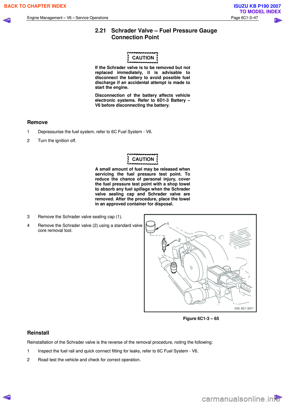
3 Remove the Schrader valve sealing cap (1).
4 Remove the Schrader valve (2) using a standard valve core removal tool.
Figure 6C1-3 – 65
Reinstall
Reinstallation of the Schrader valve is the reverse of the removal procedure, noting the following:
1 Inspect the fuel rail and quick connect fitting for leaks, refer to 6C Fuel System - V6.
2 Road test the vehicle and check for correct operation.
BACK TO CHAPTER INDEX
TO MODEL INDEX
ISUZU KB P190 2007
Page 3573 of 6020
Engine Management – V6 – Service Operations Page 6C1-3–49
1 Replace any plug that has cracked and / or broken insulation or loose electrodes.
2 Inspect the spark plugs for defects. Refer to Analysis of Spark Plug Condition in this Section for identification of the condition of spark plugs.
3 Ensure the threads are clean and in good order.
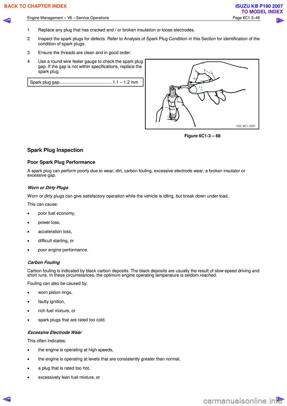
4 Use a round wire feeler gauge to check the spark plug gap. If the gap is not within specifications, replace the
spark plug.
Spark plug gap ........................................... 1.1 – 1.2 mm
Figure 6C1-3 – 68
Spark Plug Inspection
Poor Spark Plug Performance
A spark plug can perform poorly due to wear, dirt, carbon fouling, excessive electrode wear, a broken insulator or
excessive gap.
Worn or Dirty Plugs
W orn or dirty plugs can give satisfactory operation while the vehicle is idling, but break down under load.
This can cause:
• poor fuel economy,
• power loss,
• acceleration loss,
• difficult starting, or
• poor engine performance.
Carbon Fouling
Carbon fouling is indicated by black carbon deposits. The black deposits are usually the result of slow-speed driving and
short runs. In these circumstances, the optimum engine operating temperature is seldom reached.
Fouling can also be caused by:
• worn piston rings,
• faulty ignition,
• rich fuel mixture, or
• spark plugs that are rated too cold.
Excessive Electrode Wear
This often indicates:
• the engine is operating at high speeds,
• the engine is operating at levels that are consistently greater than normal,
• a plug that is rated too hot,
• excessively lean fuel mixture, or
BACK TO CHAPTER INDEX
TO MODEL INDEX
ISUZU KB P190 2007