ISUZU TFS SERIES 1997 Workshop Manual
TFS SERIES 1997
ISUZU
ISUZU
https://www.carmanualsonline.info/img/61/57182/w960_57182-0.png
ISUZU TFS SERIES 1997 Workshop Manual
Trending: roof rack, center console, diagram, manual transmission, change wheel, torque, hood open
Page 551 of 1600
CLUTCH 7C-11
Nm (kgfm/lbft)
6VD1 LHD Model
Page 552 of 1600
7C-12 CLUTCH
Nm (kgfm/lbft)
6VD1 RHD Model
Page 553 of 1600

CLUTCH 7C-13
SERVICING
Servicing refers to general maintenance procedures to be performed by qualified service personnel.
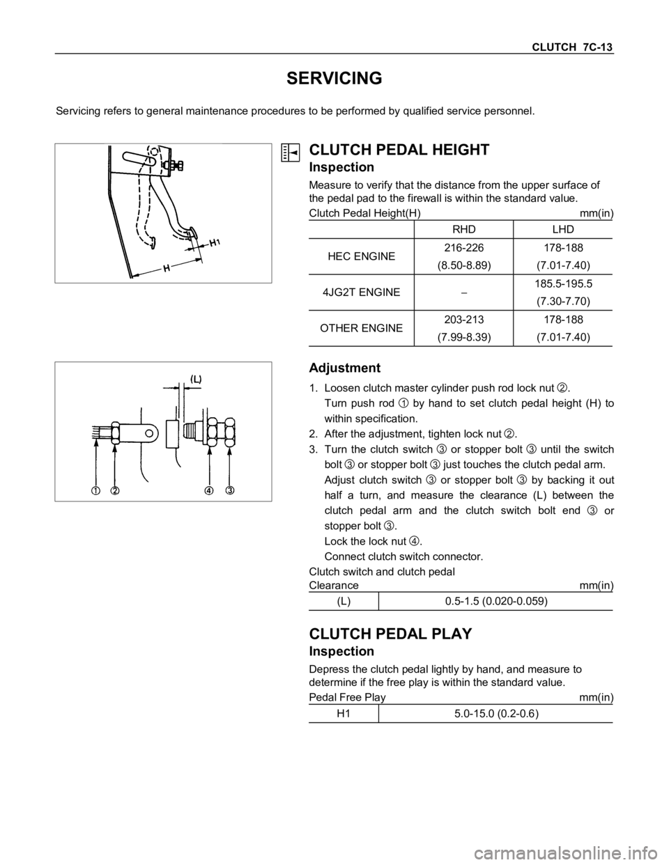
CLUTCH PEDAL HEIGHT
Inspection
Measure to verify that the distance from the upper surface of
the pedal pad to the firewall is within the standard value.
Clutch Pedal Height(H) mm(in)
RHD LHD
HEC ENGINE216-226
(8.50-8.89)178-188
(7.01-7.40)
4JG2T ENGINE185.5-195.5
(7.30-7.70)
OTHER ENGINE203-213
(7.99-8.39)178-188
(7.01-7.40)
Adjustment
1. Loosen clutch master cylinder push rod lock nut
2.
Turn push rod
1 by hand to set clutch pedal height (H) to
within specification.
2. After the adjustment, tighten lock nut
2.
3. Turn the clutch switch
3 or stopper bolt
3 until the switch
bolt
3 or stopper bolt
3 just touches the clutch pedal arm.
Adjust clutch switch
3 or stopper bolt
3 by backing it out
half a turn, and measure the clearance (L) between the
clutch pedal arm and the clutch switch bolt end
3 or
stopper bolt
3.
Lock the lock nut
4.
Connect clutch switch connector.
Clutch switch and clutch pedal
Clearance mm(in)
(L) 0.5-1.5 (0.020-0.059)
CLUTCH PEDAL PLAY
Inspection
Depress the clutch pedal lightly by hand, and measure to
determine if the free play is within the standard value.
Pedal Free Play mm(in)
H1 5.0-15.0 (0.2-0.6)
Page 554 of 1600
7C-14 CLUTCH
Bleeding Procedure
1. Bleed air from clutch operating cylinder according to the
following procedure.
Carefully monitor fluid level at master cylinder during
bleeding operation.
1. Set the paking brake.
2. Top up reservoir with recommended brake fluid.
3. Connect a transparent vinyl tube to air bleeder valve.
4. Fully depress clutch pedal several times.
5. W ith clutch pedal depressed, open bleeder valve to release
air.
6. Close bleeder valve.
7. Repeat steps 5 through 6 above until brake fluid flows from
air bleeder valve without air bubbles.
8. Bleed air from clutch damper according to the above
procedure.
9. Repeat the above bleeding procedure 1 and 2 several
times.
Page 555 of 1600
CLUTCH 7C-15
CLUTCH
REMOVAL AND INSTALLATION
HEC Engine Series
4J Engine Series
6VD1
Removal Steps
1. Transmission assembly
2. Pressure Plate assembly
3. Driven plate assembly
4. Release bearing
5. Shift fork
6. Flywheel assembly and cran bearing
(HEC Engine Series)7. Fulcrum bridge (6VD1)Installation Steps
To install, follow the removal steps in the
reverse order.
Page 556 of 1600
7C-16 CLUTCH
Important Operations - Removal
1. Transmission Assembly
Refer to “MANUAL TRANSMISSION” of section 7B and 7B1
for “REMOVAL AND INSTALLATION” procedure.
2. Clutch Pressure Plate Assembly (HEC Engine Series)
3. Driven Plate Assembly (HEC Engine Series)
(1) Use the clutch pilot aligner
1 to prevent the driven plate
assembly
2 from falling free.
Clutch Pilot Aligner : 5-8840-2634-0
(2) Loosen the clutch cover bolts in the numerical order shown
in the illustration.
(3) Remove the pressure plate assembly
3 from the flywheel.
(4) Remove the driven plate from the flywheel.
3. Driven Plate Assembly (Except HEC Engine Series)
(1) Use the pilot aligner to prevent the driven plate assembly
from falling free.
Pilot aligner: 5-8525-3001-0 (J-24547)
(2) Mark the flywheel, clutch cover and pressure plate lug for
alignment when installing.
6VD14. Release Bearing (6VD1)
Remove the release bearing from the transmission case.
Page 557 of 1600

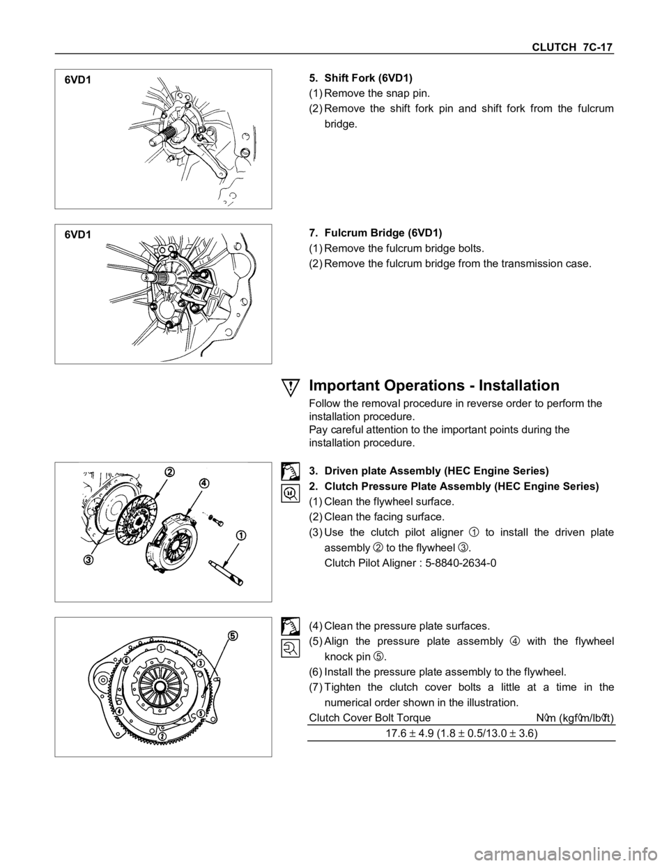
CLUTCH 7C-17
6VD15. Shift Fork (6VD1)
(1) Remove the snap pin.
(2) Remove the shift fork pin and shift fork from the fulcrum
bridge.
6VD17. Fulcrum Bridge (6VD1)
(1) Remove the fulcrum bridge bolts.
(2) Remove the fulcrum bridge from the transmission case.
Important Operations - Installation
Follow the removal procedure in reverse order to perform the
installation procedure.
Pay careful attention to the important points during the
installation procedure.
3. Driven plate Assembly (HEC Engine Series)
2. Clutch Pressure Plate Assembly (HEC Engine Series)
(1) Clean the flywheel surface.
(2) Clean the facing surface.
(3) Use the clutch pilot aligner
1 to install the driven plate
assembly
2 to the flywheel
3.
Clutch Pilot Aligner : 5-8840-2634-0
(4) Clean the pressure plate surfaces.
(5) Align the pressure plate assembly
4 with the flywheel
knock pin
5.
(6) Install the pressure plate assembly to the flywheel.
(7) Tighten the clutch cover bolts a little at a time in the
numerical order shown in the illustration.
Clutch Cover Bolt Torque N
m (kgfm/lbft)
17.6
4.9 (1.8 0.5/13.0 3.6)
Page 558 of 1600
7C-18 CLUTCH
8. Remove the clutch pilot aligner.
Note:
Do not strike the clutch pilot aligner with a hammer to
remove it.
6VD17. Fulcrum Bridge (6VD1)
(1) Install the fulcrum bridge to the transmission case.
(2) Tighten three fulcrum bridge bolts to the specified torque.
Fulcrum Bridge Bolt Torque N
m (kgm/lbft)
39 (3.9/28)
6VD15. Shift Fork (6VD1)
(1) Apply molybdenum disulfide contained type grease to the
pin hole inner circumferences and thrust surfaces.
(2) Attach the shift fork to the fulcrum bridge and insert the pin
from below of the fulcrum bridge.
(3) Install the washer and snap pin.
6VD14. Release Bearing (6VD1)
(1) Apply molybdenum disulfide contained type grease to the
areas shown in illustration.
Page 559 of 1600
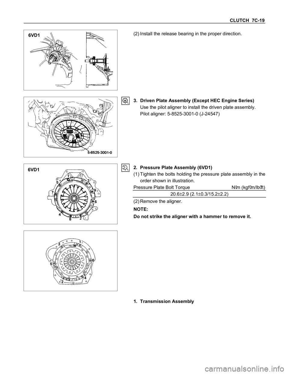
CLUTCH 7C-19
6VD1(2) Install the release bearing in the proper direction.
3. Driven Plate Assembly (Except HEC Engine Series)
Use the pilot aligner to install the driven plate assembly.
Pilot aligner: 5-8525-3001-0 (J-24547)
6VD12. Pressure Plate Assembly (6VD1)
(1) Tighten the bolts holding the pressure plate assembly in the
order shown in illustration.
Pressure Plate Bolt Torque N
m (kgfm/lbft)
20.6
2.9 (2.10.3/15.22.2)
(2) Remove the aligner.
NOTE:
Do not strike the aligner with a hammer to remove it.
1. Transmission Assembly
Page 560 of 1600

7C-20 CLUTCH
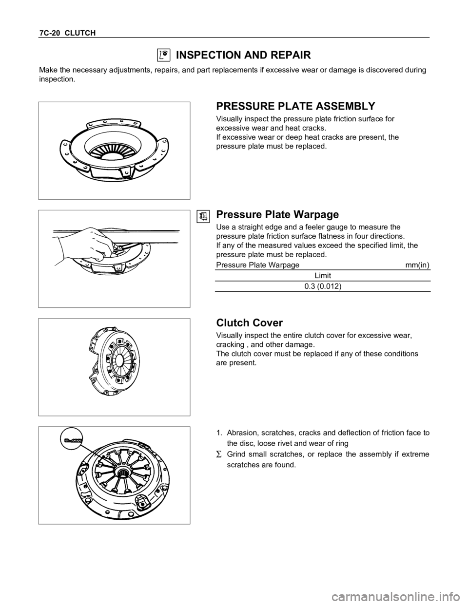
INSPECTION AND REPAIR
Make the necessary adjustments, repairs, and part replacements if excessive wear or damage is discovered during
inspection.
PRESSURE PLATE ASSEMBLY
Visually inspect the pressure plate friction surface for
excessive wear and heat cracks.
If excessive wear or deep heat cracks are present, the
pressure plate must be replaced.
Pressure Plate Warpage
Use a straight edge and a feeler gauge to measure the
pressure plate friction surface flatness in four directions.
If any of the measured values exceed the specified limit, the
pressure plate must be replaced.
Pressure Plate Warpage mm(in)
Limit
0.3 (0.012)
Clutch Cover
Visually inspect the entire clutch cover for excessive wear,
cracking , and other damage.
The clutch cover must be replaced if any of these conditions
are present.
1. Abrasion, scratches, cracks and deflection of friction face to
the disc, loose rivet and wear of ring
Grind small scratches, or replace the assembly if extreme
scratches are found.
Trending: dashboard, compression ratio, ECU, oil pressure, oil, 4WD, tire type


