tow ISUZU TROOPER 1995 Workshop Manual
[x] Cancel search | Manufacturer: ISUZU, Model Year: 1995, Model line: TROOPER, Model: ISUZU TROOPER 1995Pages: 1928
Page 17 of 1928
MAINTENANCE AND LUBRICATION OB-1
SECTION 08
MAINTENANCE AND LUBRICATION
CONTENTS
Maintenance Schedule List . . . . . . . . . . . . 08-1
Explanation of Complete Vehicle
Mai-ntenance Schedule . . . . . . . . . . . . . . 08-4
Recommended
Fluids and Lubricants . . . . 08-8
Lubricant Viscosity Chart ............... 08-9
Recommended Liquid Gasket
........... 08-11
Recommended Thread Locking Agents ... 08-11
Maintenance Service Data .............. 08-12
MAINTENANCE SCHEDULE LIST
NORMAL VEHICLE USE
The maintenance instructions in this Maintenance
Schedule are based on the assumption that the vehicle
will
be used as designed:
• to carry passengers and cargo within the limitations
specified on the tire placard located on the inside of
the glove compartment door;
• to be driven on reasonable road surfaces within
legal operating limits;
•
to be driven on a daily basis, as a general rule, for at
least several miles/kilometers;
•
to be driven on unleaded fuel
Unusual
or severe operating conditions will require
more frequent car maintenance,
as specified in the
following sections.
ITEMS
CHANGE ENGINE OIL AND OIL FIL TEA
CHANGE AUTOMATIC TRANSMISSION FLUID
SEVERE DRIVING CONDITIONS
If the vehicle is usually operated under any of the
severe driving conditions
listed below, it is
recommended that the
applicable maintenance
services be performed at the specified
interval shown
in the chart
below.
Severe driving conditions
• Repeated short trips in cold weather
• Driving in dusty areas
• Frequent idling and/or frequent low-speed
operation
• Towing a trailer
INTERVAL
Every 4,800 km (3,000 miles) or 3 months
Every
32,000 km (20,000 miles)
Page 85 of 1928
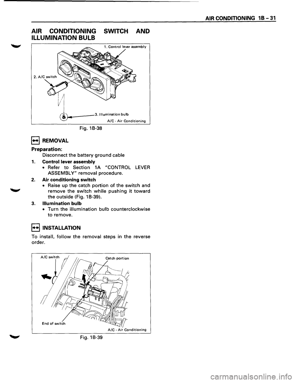
AIR CONDITIONING SWITCH AND
ILLUMINATION BULB
i-..---3. Illumination bulb
1++1 REMOVAL
Preparation:
Fig. 18-38
A/C -Air Conditioning
Disconnect the battery ground cable
1. Control lever assembly
• Refer to Section 1A "CONTROL LEVER
ASSEMBLY" removal procedure.
2. Air conditioning switch
• Raise up the catch portion of the switch and
remove the switch while pushing it toward
the outside (Fig. 1 B-39).
3. Illumination bulb
• Turn the illumination bulb counterclockwise
to remove.
I••IINSTALLATION
To install, follow the removal steps in the reverse
order.
End of switch
Fig. 18-39
AIR CONDITIONING 1 B -31
Page 134 of 1928
3A-2 FRONT END ALIGNMENT
DEFINITION OF TERMS
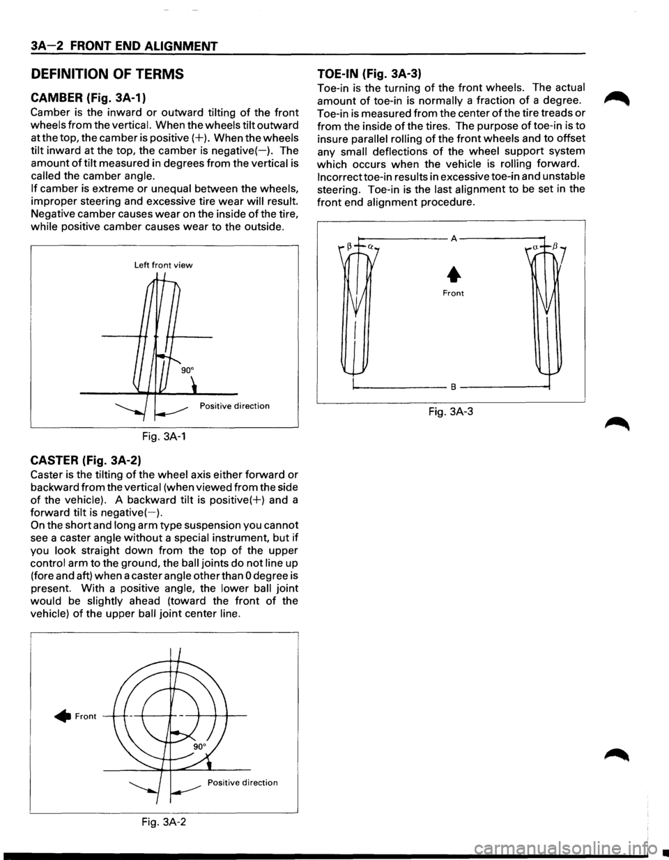
CAMBER (Fig. 3A-1)
Camber is the inward or outward tilting of the front
wheels from the vertical. When the wheels tilt outward
at the top, the camber is
positive(+). When the wheels
tilt inward at the top, the camber is negative(-). The
amount
of tilt measured in degrees from the vertical is
called the camber angle.
If camber is extreme or unequal between the wheels,
improper steering and excessive tire
wear will result.
Negative camber causes
wear on the inside of the tire,
while positive camber causes wear to the outside.
Left front view
Positive direction
Fig. 3A-1
CASTER (Fig. 3A-2)
Caster is the tilting of the wheel axis either forward or
backward from the vertical (when viewed from the side
of the vehicle). A backward tilt is positive(+) and a
forward tilt is
negative(-).
On the short and long arm type suspension you cannot
see a caster angle
without a special instrument, but if
you look straight down from the top of the upper
control arm to the ground, the
ball joints do not line up
(fore and aft) when a caster angle other than
0 degree is
present. With a positive angle, the lower
ball joint
would be slightly ahead (toward the front of the
vehicle)
of the upper ball joint center line .
• Front
Fig. 3A-2
TOE-IN (Fig. 3A-3)
Toe-in is the turning of the front wheels. The actual
amount of toe-in is normally a fraction of a degree.
Toe-in is measured
from the center of the tire treads or
from the inside of the tires. The purpose of toe-in is to
insure
parallel rolling of the front wheels and to offset
any
small deflections of the wheel support system
which occurs
when the vehicle is rolling forward.
lncorrecttoe-in results in excessive toe-in and unstable
steering. Toe-in is the last alignment to
be set in the
front end alignment procedure.
Fig. 3A-3
•
Page 142 of 1928
381 - 4 POWER STEERING GEAR AND PUMP
ON-VEHICLE SERVICE
MAINTENANCE
The hydraulic system should be kept clean and fluid
level in the reservoir should be checked at regular
intervals
and fluid added when required. Refer to
"MAINTENANCE AND LUBRICATION" in section OB
ofthe manual for type offluid to be used and intervals
for filling.
If the system contains some dirt, flush it as detailed
later
in this section. If it is exceptionally dirty, both the
pump and the gear must be completely disassembled
before further usage.
All tubes, hoses, and fittings should be inspected for
leakage at regular intervals. Fittings must be tight.
Make sure the clips, clamps and supporting tubes and
hoses are in
place and properly secured.
Power steering hoses and lines must not be twisted,
kinked or tightly bent. Air in the system will cause
spongy action and noisy operation. When a hose is
disconnected
or when fluid is lost, for any reason, the
system must be bled after refilling. Refer to "Bleeding
the Power Steering System" in this section.
FLUID LEVEL
1. Run the engine until the power steering fluid
reaches normal operating temperature, about
55°C (130°F), then shut the engine off.
2. Check the level of fluid in the reservoir.
3. If the fluid level is low, add power steering fluid
as specified in "MAINTENANCE AND LUBRI
CATION" in Section OB to the proper level and
install the receiver cap.
4. When checking the fluid level after the steering
system has been serviced,
air must be bled from
the system. Refer to "Bleeding the Power
Steering
System" in this section.
BLEEDING THE POWER STEERING
SYSTEM
When a power steering pump or gear has been
installed, or an oil line has been disconnected, the air
that has entered the system must be bled out before
the vehicle is operated. If air is allowed to remain in
the power steering fluid system, noisy and
unsatisfactory operation of the system may result.
BLEEDING PROCEDURE
When bleeding the system, and any time fluid is
added
to the power steering system, be sure to use
only power steering fluid as specified in
"MAINTENANCE AND LUBRICATION" in section OB.
1. Fill the pump fluid reservoir to the proper level
and let the fluid settle for at least two minutes.
2. Start the engine and let it run for a few seconds.
Do
not turn the steering wheel. Then turn the
engine off.
3. Add fluid if necessary.
4. Repeat the above procedure until the fluid level
remains constant after running the engine.
5. Raise the front end of the vehicle so that the
wheels are off the ground.
6. Start the engine. Slowly turn the steering wheel
right and left, lightly contacting the wheel stops.
7. Add power steering fluid if necessary.
8. Lower the vehicle and turn the steering wheel
slowly from lock to lock.
9. Stop the engine. Check the fluid level and refill
as required.
10.
If the fluid is extremely foamy, allow the vehicle
to stand a few minutes and repeat the above
procedure.
~ INSPECT
• Belt for tightness.
• Pulley for looseness or damage. The pulley
should not wobble with the engine running.
• Hoses so they are not touching any other parts
of the vehicle.
• Fluid level
and fill to the proper level.
FLUSHING THE POWER STEERING
SYSTEM
1. Raise the front end of the vehicle off the ground
until the wheels are free to turn.
2. Remove the fluid return line at the pump inlet
connector and plug the connector port on the
pump.
Position the line toward a large container to
catch the draining fluid.
3. While running the engine at idle, fill the reservoir
with new power steering fluid. Turn the steering
wheel in both directions. DO NOT contact wheel
stops or hold the wheel in a corner, or fluid will
stop and the pump will be in pressure relief mode.
A sudden
overflow from the reservoir may
develop if the wheel is held at a stop.
4. Install all the lines and hoses. Fill the system with
new power steering fluid and bleed the system
as described in "Bleeding The Power Steering
System". Operate the engine for about 15
minutes.
Remove the
pump return line at the pump inlet
and plug the connection on the pump. While
refilling the reservoir, check the draining fluid for
contamination. If foreign material is still evident,
replace all lines, disassemble and clean or replace
the power steering system components. Do not
re-use any drained power steering fluid.
~
~
Page 151 of 1928
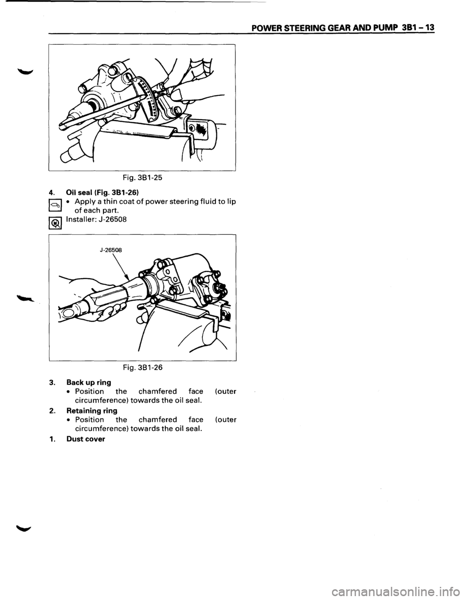
Fig. 381-25
4. Oil seal (Fig. 381-26)
~ • Apply a thin coat of power steering fluid to lip
D of each part.
l®..llnstaller: J-26508
J-26508
Fig. 381-26
3. Back up ring
• Position the chamfered face (outer
circumference) towards the oil seal.
2. Retaining ring
• Position the chamfered face (outer
circumference) towards the oil seal.
1. Dust cover
POWER STEERING GEAR AND PUMP 381 -13
Page 297 of 1928
FRONT DRIVING AXLE 4C-19
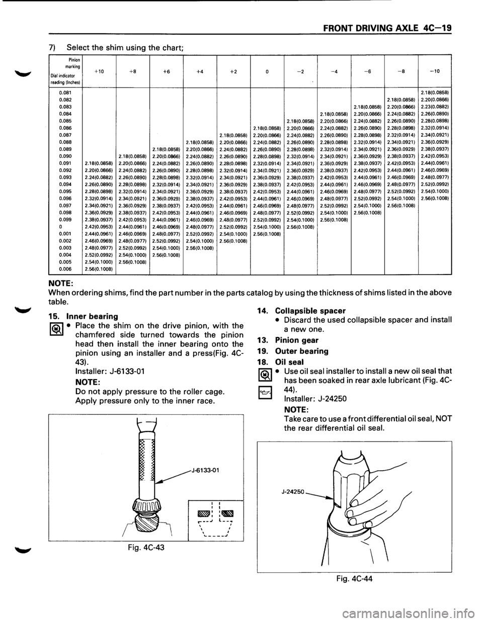
7) Select the shim using the chart;
Pinion marking +10 +8 +6 +4 +2 0 -2 -4 -6 -8 -10 Dial indicator reading !Inches)
0.081 2.18(0.0858)
0.082 2.18(0.0858) 2.20(0.0866)
0.083
2.1 8(0.0858) 2.20(0.0866)
2.23(0.0882)
0.084 2.1 8(0.0858) 2.20(0.0866) 2.24(0.0882) 2.26(0.0890)
0.085 2.18(0.0858) 2.20(0.0866) 2.24(0.0882)
2.26(0.0890) 2.28(0.0898)
0.086 2.18(0.0858) 2.20(0.0866) 2.24(0.0882)
2.26(0.0890) 2.28(0.0898) 2.32(0.0914)
0.087 2.18(0.0858) 2.20(0.0866)
2.24(0.0882) 2.26(0.0890) 2.28(0.0898) 2.32(0.0914) 2.34(0.0921) 0.088 2.18(0.0858) 2.20(0.0866) 2.24(0.0882) 2.26(0.0890) 2.28(0.0898) 2.32(0.0914) 2.34(0.0921) 2.36(0.0929) 0.089 2.18(0.0858) 2.20(0.0866) 2.24(0.0882) 2.26(0.0890)
2.28(0.0898) 2.32(0.0914) 2.34(0.0921) 2.36(0.0929) 2.38(0.0937)
0.090 2.18(0.0858) 2.20(0.0866) 2.24(0.0882) 2.26(0.0890) 2.28(0.0898) 2.32(0.0914) 2.34(0.0921) 2.36(0.0929)
2.38(0.0937)
2.42(0.0953)
0.091 2.18(0.0858)
2.20(0.0866) 2.24(0.0882) 2.26(0.0890) 2.28(0.0898) 2.32(0.0914) 2.34(0.0921) 2.36(0.0929) 2.38(0.0937) 2.42(0.0953) 2.44(0.0961
I
0.092 2.20(0.0866) 2.24(0.0882) 2.26(0.0890) 2.28(0.0898) 2.32(0.0914) 2.34(0.0921) 2.36(0.0929) 2.38(0.0937) 2.42(0.0953) 2.44(0.0961)
2.46(0.0969) 0.093 2.24(0.0882)
2.26(0.0890) 2.28(0.0898) 2.32(0.0914) 2.34(0.0921 I 2.36(0.0929) 2.38(0.0937) 2.42(0.0953) 2.44(0.0961 I 2.46(0.0969) 2.48(0.0977)
0.094 2.26(0.0890)
2.28(0.0898) 2.32(0.0914) 2.34(0.0921) 2.36(0.0929) 2.38(0.0937) 2.42(0.0953) 2.44(0.0961
I 2.46(0.0969) 2.48(0.0977) 2.52(0.0992)
0.095 2.28(0.0898) 2.32(0.0914)
2.34(0.0921 I 2.36(0.0929) 2.38(0.0937) 2.42(0.0953) 2.44(0.0961 I 2.46(0.0969) 2.48(0.0977) 2.52(0.0992) 2.54(0.1 000)
0.096 2.32(0.0914)
2.34(0.0921) 2.36(0.0929) 2.38(0.0937) 2.42(0.0953) 2.44(0.0961) 2.46(0.0969) 2.48(0.0977) 2.52(0.0992) 2.54(0.1000)
2.56(0.1
008)
0.097 2.34(0.0921) 2.36(0.0929)
2.38(0.0937) 2.42(0.0953) 2.44(0.0961 I 2.46(0.0969) 2.48(0.0977) 2.52(0.0992)
2.54(0.1 000) 2.56(0.1 008)
0.098 2.36(0.0929)
2.38(0.0937) 2.42(0.0953) 2.44(0.0961 I 2.46(0.0969) 2.48(0.0977)
2.52(0.0992) 2.54(0.1 000) 2.56(0.1 008)
0.099 . 2.38(0.0937) 2.42(0.0953) 2.44(0.0961) 2.46(0.0969)
2.48(0.0977) 2.52(0.0992)
2.54(0.1000) 2.56(0.1 008)
0 2.42(0.0953) 2.44(0.0961) 2.46(0.0969) 2.48(0.0977) 2.52(0.0992) 2.54(0.1 000) 2.56(0.1008)
0.001 2.44(0.0961)
2.46(0.0969) 2.48(0.0977) 2.52(0.0992) 2.54(0.1 000) 2.56(0.1008)
0.002 2.46(0.0969) 2.48(0.0977) 2.52(0.0992) 2.54(0.1 000) 2.56(0.1 008)
0.003 2.48(0.0977) 2.52(0.0992) 2.54(0.1 000) 2.56(0.1 008)
0.004 2.52(0.0992) 2.54(0.1 000) 2.56(0.1 008)
0.005 2.54(0.1 000) 2.56(0.1 008)
0.006 2.56(0.1 008)
NOTE:
When ordering shims, find the part number in the parts catalog by using the thickness of shims listed in the above
table.
15. Inner bearing
ria\~ • Place the shim on the drive pm1on, with the
~ chamfered side turned towards the pinion
head then
install the inner bearing onto the
pinion using an
installer and a press(Fig. 4C-
43).
Installer: J-6133-01
NOTE:
Do not apply pressure to the roller cage.
Apply pressure only to the inner race.
Fig.
4C-43
J-6133-01
I I I I
~::~ r--.J , I I '\...-___ J
14. Collapsible spacer
• Discard the used collapsible spacer and install
a new one.
13. Pinion gear
19.
Outer bearing
18.
Oil seal
ria\~ • Use oil seal installer to install a new oil seal that
~ has been soaked in rear axle lubricant (Fig. 4C-
I:;;:;I 44) .
t.::::::::.l Installer: J-24250
NOTE:
Take care to use a front differential oil seal, NOT
the rear differential oil seal.
J-24250
Fig. 4C-44
Page 322 of 1928
SA-2 HYDRAULIC BRAKES
BRAKE SYSTEM DIAGNOSIS
ROAD TESTING THE BRAKES
Brake Test
Brakes should be tested on a dry, clean, reasonably
smooth and
level roadway. A true test of brake
performance cannot be made
if the roadway is
wet, greasy
or covered with loose dirt so that all
tires do not grip the road equally. Testing will also
be adversely affected if the roadway is crowned so
as to throw the weight of the vehicle toward
wheels on one side or if the roadway is so rough
that wheels tend to bounce. Test the brakes at dif
ferent vehicle speeds with both light and heavy
pedal pressure; however, avoid locking the wheels
and sliding the tires. Locked wheels and sliding
tires do not indicate brake efficiency, since heavily
braked but turning wheels will stop the vehicle in
less distance than locked wheels. More tire-to-road
friction is present
with a heavily braked turning tire
then
with a sliding tire.
The standard brake system is designed and
balanced
to avoid locking the wheels except at very high
deceleration
levels.
It
is designed this way because the shortest stopping
distance and best
control is achieved without brake
lock-up.
Because of high deceleration capability, a firmer pedal
may be felt at higher deceleration levels.
External Conditions That Affect Brake
Performance
1.
2.
3.
Tires: Tires having unequal contact and grip on
the road
will cause unequal braking. Tires must
be equally inflated, identical in size, and the tread
pattern
of right and left tires must be approxi
mately equal.
Vehicle loading:
A heavily loaded vehicle requires
more braking effort.
Wheel Alignment: Misalignment of the wheels,
particularly
in regard to excessive camber and
caster,
will cause the brakes to pull to one side.
BRAKE FLUID LEAKS
With engine running at idle and the transmission in
"Neutral", depress the brake pedal and hold a constant
foot pressure on the pedal. If pedal gradually falls
away with the constant pressure, the hydraulic system
may be leaking.
Check the master cylinder fluid level. While a slight
drop in reservoir level will result from normal lining
wear, an abnormally low level in reservoir indicates a
leak in the system. The hydraulic system may be
leaking internally as well as externally. Refer to
"Master Cylinder Inspection". Also, the system may
appear
to pass this test but still have slight leakage. If
fluid level
is normal, check the vacuum booster
push rod
length. If an incorrect length push rod is
found, adjust
or replace the push rod. Check the
brake
pedal travel and the parking brake adjust
ment.
When checking the
fluid level, the master cylinder fluid
level
may be low from the "MAX" mark if the front and
rear
linings are worn. This is not abnormal.
WARNING LIGHT OPERATION
When the ignition switch is in the START position,
the
"BRAKE" warning light should glow and go off
when the ignition switch returns to the ON position.
The
following conditions will activate the "BRAKE"
light:
1. Parking brake applied. The light should be on
whenever the parking brake is applied and the
ignition switch is on.
2. Low fluid level. A low fluid level in the master
cylinder will turn the "BRAKE" light on (Except
Rear
Wheel Antilock Brake System (RWAL)
model).
3. During engine cranking the "BRAKE" light
should
remain on. This notifies the driver that
the warning circuit is operating properly.
4. In the event of a front or rear system malfunc
tion (RWAL model only).
5. In the event of RWAL malfunction (RWAL
model only. Refer to Section 5A3).
ANTILOCK BRAKE SYSTEM (RWAL or
ABS}
Refer to Section 5A3 or 5A4 for inspection and di
agnosis procedure of the hydraulic unit.
..
Page 414 of 1928
5A4-4 4-WHEEL ANTILOCK BRAKE SYSTEM (ABS)
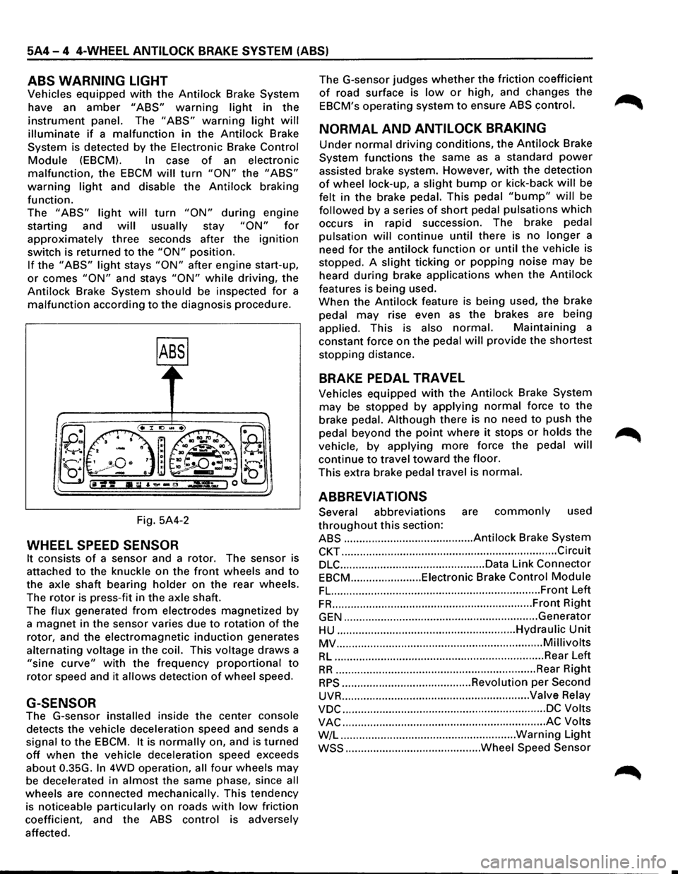
ABS WARNING LIGHT
Vehicles equipped with the Antilock Brake System
have an
amber "ABS" warning light in the
instrument panel. The "ABS" warning light will
illuminate if a malfunction in the Antilock Brake
System is detected by the Electronic Brake
Control
Module (EBCM). In case of an electronic
malfunction, the EBCM will turn "ON" the "ABS"
warning light and disable the Antilock braking
function.
The
"ABS" light will turn "ON" during engine
starting and
will usually stay "ON" for
approximately three seconds after the ignition
switch is returned to the "ON" position.
If the "ABS" light stays "ON" after engine start-up,
or comes "ON" and stays "ON" while driving, the
Antilock Brake System should be inspected
for a
malfunction according to the diagnosis procedure.
Fig. 5A4-2
WHEEL SPEED SENSOR
It consists of a sensor and a rotor. The sensor is
attached
to the knuckle on the front wheels and to
the axle shaft bearing holder on the rear wheels.
The
rotor is press-fit in the axle shaft.
The
flux generated from electrodes magnetized by
a magnet in the sensor varies due to rotation of the
rotor, and the electromagnetic
induction generates
alternating voltage in
the coil. This voltage draws a
"sine curve" with the frequency proportional to
rotor speed and it allows detection of wheel speed.
G-SENSOR
The G-sensor installed inside the center console
detects the vehicle deceleration speed and sends a
signal
to the EBCM. It is normally on, and is turned
off when the vehicle deceleration speed exceeds
about 0.35G.
In 4WD operation, all four wheels may
be decelerated in almost the same phase, since all
wheels are connected mechanically. This tendency
is noticeable particularly on roads
with low friction
coefficient, and the
ABS control is adversely
affected. The
G-sensor judges
whether the friction coefficient
of road surface is low or high, and changes the
EBCM's operating system to ensure ABS control.
NORMAL AND ANTILOCK BRAKING
Under normal driving conditions, the Antilock Brake
System functions the same
as a standard power
assisted brake system. However, with the detection
of wheel lock-up, a slight bump or kick-back will be
felt in the brake pedal. This pedal
"bump" will be
followed by a series of short pedal pulsations which
occurs in rapid succession. The brake pedal
pulsation
will continue until there is no longer a
need
for the antilock function or until the vehicle is
stopped. A
slight ticking or popping noise may be
heard
during brake applications when the Antilock
features is being used.
When the
Antilock feature is being used, the brake
pedal
may rise even as the brakes are being
applied. This is also
normal. Maintaining a
constant force on the pedal
will provide the shortest
stopping distance.
BRAKE PEDAL TRAVEL
Vehicles equipped with the Antilock Brake System
may be stopped by applying normal force to the
brake pedal.
Although there is no need to push the
pedal beyond the
point where it stops or holds the ~
vehicle, by applying more force the pedal will
continue to travel toward the floor.
This extra brake pedal travel is normal.
ABBREVIATIONS
Several abbreviations are commonly used
throughout this section:
ABS .......................................... Antilock Brake System
CKT ...................................................................... Circuit
DLC ............................................... Data Link Connector
EBCM ....................... Eiectronic Brake Control Module
FL. ................................................................... Front Left
FR ................................................................. Front Right
GEN ............................................................... Generator
HU .......................................................... Hydraulic Unit
MV ................................................................... Millivolts
RL .................................................................... Rear Left
RR ................................................................. Rear Right
RPS .......................................... Revolution per Second
UVR ............................................................. Valve Relay
VDC .................................................................. DC Volts
VAC .................................................................. AC Volts
W/L .........................................................
Warning Light
WSS ............................................ Wheel Speed Sensor
Page 415 of 1928
4-WHEEL ANTILOCK BRAKE SYSTEM (ABS) 5A4-5
DIAGNOSIS
GENERAL INFORMATION
ABS troubles can be classified to two types, those
which can be detected by the ABS warning light
and those which can be detected as a vehicle
abnormality by the driver.
In either case, locate the fault in accordance with
the "BASIC DIAGNOSTIC FLOWCHART" and repair.
Please refer to Section 5A, 5A1, 5A2, 5C for the
diagnosis
of mechanical troubles such as brake
noise, brake
judder (brake pedal or vehicle vibration
felt when braking), uneven braking, and parking
brake
trouble.
ABS SYSTEM SERVICE PRECAUTIONS
Required Tools and Items
Box Wrench
• Brake Fluid
Special Tool
Some diagnosis procedures in this section require
the installation of a special tool.
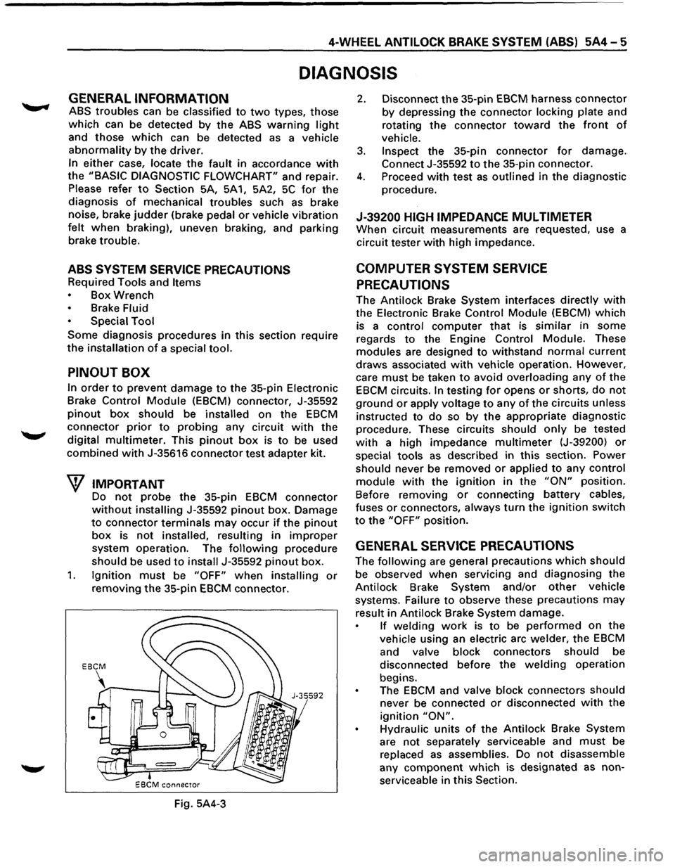
PINOUT BOX
In order to prevent damage to the 35-pin Electronic
Brake
Control Module (EBCM) connector, J-35592
pinout box should be installed on the EBCM
connector prior to probing any circuit with the
digital
multimeter. This pinout box is to be used
combined with J-35616 connector test adapter kit.
W IMPORTANT
Do not probe the 35-pin EBCM connector
without installing J-35592 pinout box. Damage
to connector terminals may occur if the pinout
box is not installed, resulting in improper
system operation. The following procedure
should be used to install J-35592 pinout box.
1. Ignition must be "OFF" when installing or
removing the 35-pin EBCM connector.
Fig. 5A4-3
2. Disconnect the 35-pin EBCM harness connector
by depressing the connector locking plate and
rotating
the connector toward the front of
vehicle.
3. Inspect the 35-pin connector for damage.
Connect J-35592 to the 35-pin connector.
4. Proceed with test as outlined in the diagnostic
procedure.
J-39200 HIGH IMPEDANCE MUL TIMETER
When circuit measurements are requested, use a
circuit tester
with high impedance.
COMPUTER SYSTEM SERVICE
PRECAUTIONS
The Antilock Brake System interfaces directly with
the Electronic Brake Control Module (EBCM) which
is a
control computer that is similar in some
regards
to the Engine Control Module. These
modules are designed to withstand normal current
draws associated with vehicle operation. However,
care
must be taken to avoid overloading any of the
EBCM circuits. In testing for opens or shorts, do not
ground or apply voltage to any of the circuits unless
instructed to
do so by the appropriate diagnostic
procedure. These circuits should only be tested
with a high impedance multimeter (J-39200) or
special tools as described in this section. Power
should never be removed or applied to any control
module with the ignition in the "ON" position.
Before removing
or connecting battery cables,
fuses
or connectors, always turn the ignition switch
to the "OFF" position.
GENERAL SERVICE PRECAUTIONS
The following are general precautions which should
be observed when servicing and diagnosing the
Antilock Brake System and/or
other vehicle
systems. Failure
to observe these precautions may
result in Antilock Brake System damage.
If welding work is to be performed on the
vehicle using an electric arc welder, the EBCM
and valve block connectors should be
disconnected before the
welding operation
begins.
The
EBCM and valve block connectors should
never be connected or disconnected with the
ignition "ON".
Hydraulic units of the Antilock Brake System
are not separately serviceable and must be
replaced
as assemblies. Do not disassemble
any
component which is designated as non
serviceable in
this Section.
Page 511 of 1928
ENGINE DIAGNOSIS 6-13
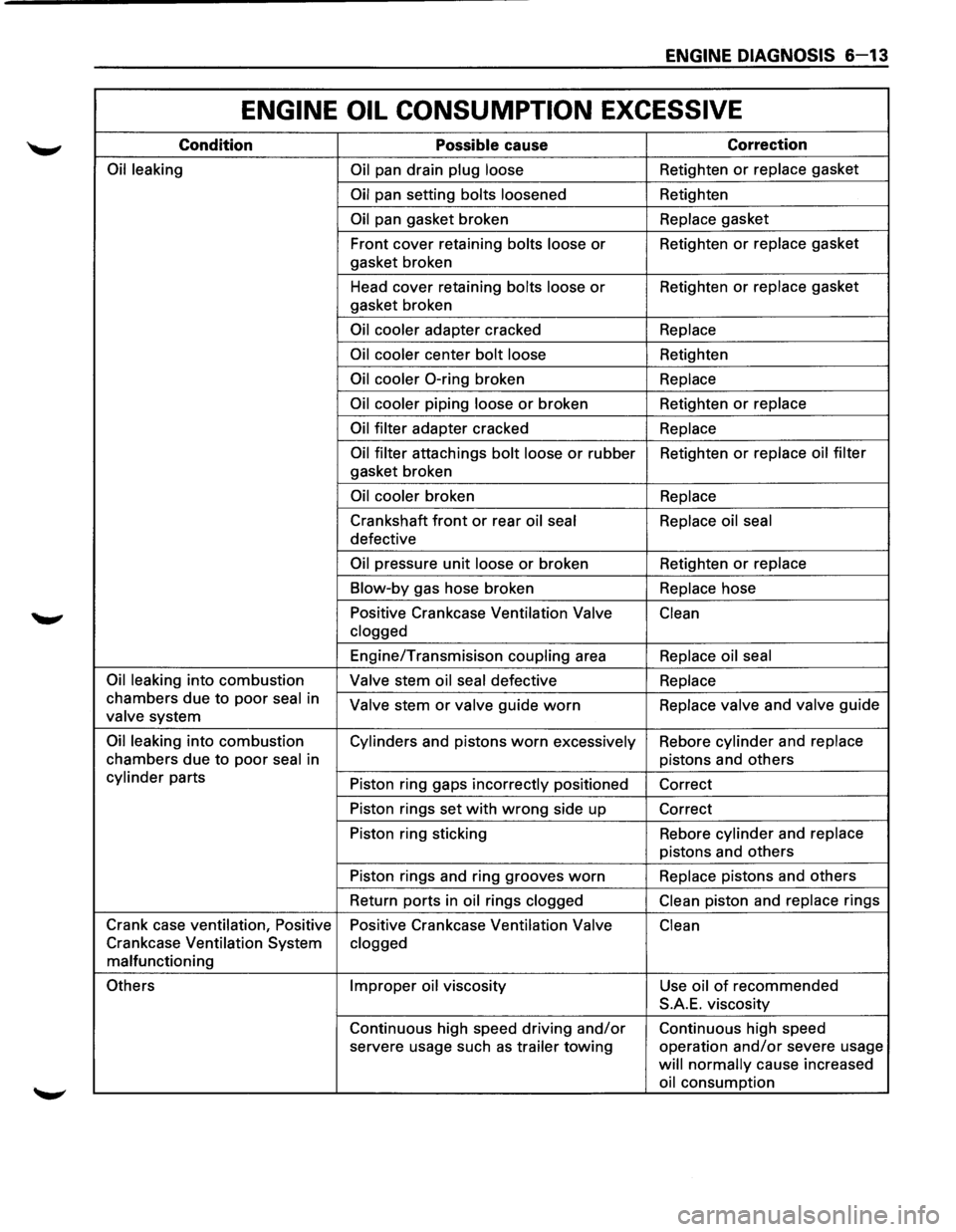
ENGINE OIL CONSUMPTION EXCESSIVE
Condition Possible cause Correction
Oil leaking
Oil pan drain plug loose Retighten or replace gasket
Oil pan setting bolts loosened Retighten
Oil pan gasket broken Replace gasket
Front cover retaining
bolts loose or Retighten or replace gasket
gasket broken
Head cover retaining
bolts loose or Retighten or replace gasket
gasket broken
Oil cooler adapter cracked Replace
Oil cooler
center bolt loose Retighten
Oil cooler 0-ring broken Replace
Oil cooler
piping loose or broken Retighten or replace
Oil filter
adapter cracked Replace
Oil filter
attachings bolt loose or rubber Retighten or replace oil filter
gasket broken
Oil cooler broken Replace
Crankshaft front or rear oil seal Replace oil seal
defective
Oil pressure unit loose or broken Retighten or replace
Blow-by
gas hose broken Replace hose
Positive Crankcase Ventilation
Valve
Clean
clogged
Engine/Transmisison coupling area Replace oil seal
Oil leaking
into combustion Valve stem oil seal defective Replace
chambers due to poor seal in Valve stem or valve guide worn Replace valve and valve guide valve system
Oil leaking into combustion
Cylinders and pistons worn excessively Rebore cylinder and replace
chambers
due to poor seal in pistons and others
cylinder parts
Piston ring gaps incorrectly positioned
Correct
Piston rings set
with wrong side up
Correct
Piston ring sticking Rebore
cylinder and replace
pistons and others
Piston rings and ring grooves
worn Replace pistons and others
Return ports in
oil rings clogged Clean piston
and replace rings
Crank case ventilation, Positive
Positive Crankcase Ventilation
Valve Clean
Crankcase Ventilation System clogged
malfunctioning
Others Improper oil viscosity
Use oil of recommended
S.A.E. viscosity
Continuous high speed driving
and/or Continuous high speed
servere usage such
as trailer towing operation and/or severe usage
will normally cause increased
oil consumption