tow ISUZU TROOPER 1995 Owner's Guide
[x] Cancel search | Manufacturer: ISUZU, Model Year: 1995, Model line: TROOPER, Model: ISUZU TROOPER 1995Pages: 1928
Page 888 of 1928
7A-16 AUTOMATIC TRANSMISSION (4L30-E)
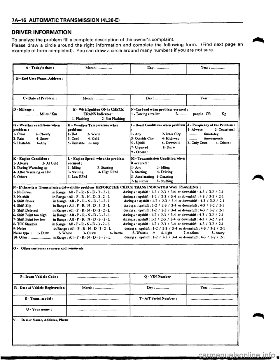
DRIVER INFORMATION
To analyze the problem fill a complete description of the owner's complaint.
Please draw a circle around the right information and complete the following form. (Find next page an
example of form completed). You can draw a circle around many numbers if you are not sure.
A-Today' a date : Month: ............... Day:·············· Year: ...............
B-Ead User Name, Address :
C-Dat~ of Problem : Month: ..................... Day: ................. Year: ................
D-Mileaae: E-With Ignirioa. ON ia OIECK F -Car load wheo proHem oceand :
...............
Miles/Km TRANS lodicator : 1 - Towing a trailer 2-.......... people OR ......... Kg
1-Flashing 2-Not Flashing
G-Weather coa.ditiou whea. H-Weather Temperature whea I -Road Cooditioaa wheu problem J-Frequeucy ofthe Problem :
!Problem: problem: : 1-Always 2-Occuional :
1-Clear 2-Cloudy 1-Hot 2-Warm 1-Any 2-Inter City ........ times/day,
3-
Rain 4-Snow 3-Cool 4-Cold 3-Outsid~ City 4- Highway douooo times/month
5- Unstable
6-Any 5-Unstable 6- Any S-Uphill 6-Downhill 3-
Only Once 4-Otheu:
7-Unpaved 8-Snow
9-Others:
IK-EJI&iae Coaditioa : L-Eagiae Spttd whca the problem M-Traasmissiou Coa.diriou wbea
1-Always 2- At Cold occand: it occund:
3-During Warming up 1-Idling 2-Starting 1-Any 2-
Idling
4-After Warming or Hot 3-Stalling 4-HighRPM 3-Starting 4-Driving
5-Others 5-LowRPM 5-Accelerating 6-Coasting
7-Inc:omer 8-Shifting
N-If then b a Trauamiuioa drivcabillty problem BEFORE TIIE CHECK TRANS
INDICATOR WAS FI..ASHING :
I-No Power in Range: All-P-R-N-D-3 -1-L during
a : upshift : 1-2 I 2-3 I 3~4 or downshift : 4-3 I 3-2 I 2-1
2-No shift in Range :All-P-R-N-D-3-2-L during a: upshift
: 1-2 I 2-3 I 3-4 or downshit : 4-3 I 3-2 I 2-1
3- Shift Shock in Range: All-P-R-N-D -3-2-L during a
:upshift : 1-2 I 2-3 I 3-4 or downshift : 4-3 I 3-2 I 2-1
4-Shift Slip in Range: Ali-P-R-N -D-3 -2 -L during a: upshift : 1-2 I 2-3 I 3-4 or downshift : 4-3 I 3-2 I 2-1
5-Shift Delayed in Range : All -P -R-N - D - 3 - 2 - L during a: upshift :
1-2 I 2-3 I 3-4 or downshift : 4-3 I 3-2 I 2-1
6-Shi1 Point too high in Range :All -P-R-N-D-3-2. L during a: upshift:
1-2 I 2-3 I 3-4 or downshift: 4-3 I 3-2 I 2-1
7-Shift Point too low
in Range : All -P -R-N-D-3 -2-L during
a : upshift : 1-2 I 2-3 I 3-4 or downshift : 4-3 I 3-2 I 2-1
S-TCC Shudder in Range :All-P-R. N-D-3-2-L during a: upshift
: 1-2 I 2-3 I 3-4 or downshift : 4-3 I 3-2 I 2-1
9-Noise in Range : All -P -R-N - D - 3 - 2 - L during a: upshift : 1-2 I 2-3 I 3-4 or downshift : 4-3 I 3-2 I 2-1
INolae type: 1-Buzz 2-Whine 3-Clunk 4-Rattle S-Whistle II 6-light 7-medium 8-hoavy
10-Other: ..................... in Range : All -P -R-N - D - 3 - 2 - L during a: upshit :
1-2 I 2-3 I 3-4 or downshift : 4-3 I 3-2 I 2-1
0-Other cDitomer co aura. aad commeats
P •
bUZD Vebiele Code : ooo,0ooooooooooou• .. ouooooooooooooo•••••o•U Q-VIN Number ··················\
··················\
··········
R-Date orVebiclc Regjatratiou Month: ..................... Day: .............. Year: ...............
S • Traua. model: .................... -. ......................... T-Aff Serial Number : uo••••••••••••••••••\
•••oo•oooooooooooooouooo
U-Your aame: ··················\
··················\
··········
y. Dealer Naau, Addn .. , Pbou~
•
Page 889 of 1928
AUTOMATIC TRANSMISSION (4L30-E) 7A-17
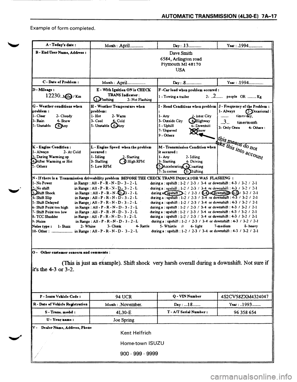
Example of form completed.
A-Today's date : Month : April .............. Day: .13 ............. YOM: .1994 ..............
B-Ead U.er Name, Address : Dave Smith
6584, Arlington road
P1ymoutll Ml 48170
USA
C-Date or Problem :
Month : April... ................ Day:.8 ................ You : .1994 ...............
D-Mileace: E-With lguirioa ON is CHECK F -Car load whcu problem occartd:
12230 .. J.@1Km @! TRANS ludicator: 1 -Towing a trailer 2-.. 2 ....... people OR ......... Kg ashing 2-
Not Flashing
G-Weatbtr couditious wbeu H-Weather Temperature wheu I-Road Conditions ""hen problem J-Frequency or the Problem : problem: problem: : 1-Always ~sionaJ :
1-Clear 2- Cloudy 1-Hot 2-Wann 1-Any l.-lltto:r City ........ fio•~s/ y,
3-
Rain 4-Snow 3-Cool ~d 3-Owside City (j}Highway .. .3 ... tim~stmonth 5-Unstable (!).ny S-Unstable 6- y 5-Uphill ti-Downhill 3-Only Once 4-Otb.n: 7-Unpaved )8t.now 9-Others .......___
l!Jis 111P.
K -Euciue Coa.dition : L-Engiue Speed wbea the problem M-Traasmiuioo Condition wheu ~e IJJis 7~~· do l1ot
!-Always 2-At Cold occared: it occared: lJto a
~ing Warming up 1-Idling 2-Starting 1-Any 2-Idling C'collnt
er Warming
or Hot 3-Stalling (3Higt~RPM 3-Starting 4-Driving
5-Others S-Low RPM (~cceleratin~~~~g 7-lr. comer 8-JUftmg
IN-Irtbcrt is a Transmission drive ability problem BEFORE THE CHECK TRANS INVJCATOR WAS FLASHING :
1-NoPower in Range : All -P -R-N-D-3 - 2 - L during a: upshift: 1-2 I 2-3 J 3-4 or downshift: 4-3 I 3-2 / 2-1
~hift inR.ange:AII-P-R-~-0-3-2-L during a : up~hifl : 1-2 I 2-3 ! 3-4 01 uowushifl : ~-3 I 3-2 I 2-1 Shock in Range: AII-P-R-N -~ -2-L during·~-: I 2-3 I (Do~:Qi 3-2 I 2-l 4-Shift Slip in Range : All -P -R-N - D - 3 - 2 - L during a: ups "ft : 1-2 I 2-3 / 3-4 or dov.nshift : 4-3 / 3-2 I 2-1
S-Shift Delayed
in Range,.: All -P -R-N -D-3 -2 - L during
a :upshift : 1-2 I 2-3 I 3-4 or dovmshift : 4-3 I 3-2 I 2-1
6-Shift Point too higJl in Range :All -P-R-N • D-3-2-J.. during a : upshift : 1-2 I 2-3 ! 3-4 or downshift : 4-3 I 3-2 I 2-1 7-Shift Point too low
in Range :All -P-R-N-D-3-2; L during a :upshift : 1-2 I 2-3 I 3-4 or downshift : 4-3 I 3-2 I 2-1
8-TCC Shudder
in Range : All -P - R
- N - D - 3 -2 - L during
a :upshift : 1-2 I 2-3 I 3-4 or downshift : 4-3 I 3-2 I 2-1
9-Noise in Range : All -P -R-N -D-3 -2-L during a :upshift : 1-2 I 2-3 I 3-4 or downshift : 4-3 I 3-2 I 2-1
~oise type: 1-Buzz 2-Whine 3-Clunk 4-lWtle S-Whistle II 6-light 7-medium 8-heavy
10-0thor: ..................... inR.ange:AII-P-R-N-0-3-2-L during
a :upshift : 1-2 I 2-3 I 3-4 or downshift : 4-3 I 3-2 I 2-1
0-Other customer co accra aa.d com meat• :
(This is just an e~ample ). Shift shock very harsh
overall during a downshift. Not sure if
it's the 4-3 or 3-2.
P-huza Vehicle Code : 94 UCR Q -VIN Number 4S2CV58ZXM432404 7
R-Date ofVehieJe Re~stratioa Month : .November. Day: ... .18 ........ Year: . .1993 .........
S -Traaa.. mtldel : 4L30-E T-Aff Serial Number : 96 358 654
U-Yoali'D.ame: Joe Spring
V-Dealer Name, Address, Phooe
Kent Helfrich
Home-town ISUZU
900 -999 -9999
Page 892 of 1928
7 A-20 AUTOMATIC TRANSMISSION (4L30-E)
CHECKING TRANSMISSION FLUID
LEVEL AND CONDITION
Checking fluid level and condition (color and odor)
at
regular intervals will provide early diagnosis
information about the transmission. This inform
ation may be used to correct a condition that, if not
detected early, could result in major transmission
repairs.
IMPORTANT: When new, automatic transmission
fluid is red in color. As the vehicle is driven, the
transmission
fluid will begin to look darker in color.
The
color may eventually appear light brown.
A DARK
brown color with burnt odor may indicate
excessive
fluid deterioration and signal a need for
fluid change.
FLUID LEVEL
When adding
or changing fluid, use only DEXRON
®-Ill.
Refer to the Maintenance and Lubrication (Section 0
of this manual) for maintenance information and
servicing
interval.
\f CAUTION: DO NOT OVERFILL
Overfilling will cause foaming, loss ~f fluid,
abnormal shifting and possible damage to
the transmission.
1. Start engine and drive vehicle until normal AfT
oil operating temperature is reached:
NOTE: The automatic transmission fluid level
must be checked with the vehicle at normal
A/T oil operating temperature: 75 TO 85°C
(167 TO 185°F) MEASURED WITH TECH1 SCAN
TOOL.
Temperature will greatly affect transmission
fluid level.
If the vehicle is not at normal AfT oil operating
temperature and the proper checking
procedures are
not followed, the result could
be a false reading of the fluid level indicator
and
an incorrect adjustment of the fluid level.
2. Park vehicle on level ground.
3. Move gear selector to "Park".
4. Apply parking brake and block wheels.
5. Allow vehicle to idle for 3 minutes with all
accessories turned off.
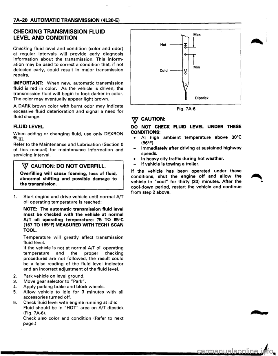
6. Check fluid level with engine running at idle:
Fluid should
be in "HOT" area on AfT dipstick
(Fig. 7A-6).
Check also color and condition (Refer to next
page.)
Hot
Cold ---IIU 0
0
Min
Dipstick
Fig. 7A-6
\f CAUTION:
DO NOT CHECK FLUID LEVEL UNDER THESE
CONDITIONS: •
At high ambient temperature above 30°C
(86°F).
Immediately after driving at sustained highway
speeds.
• In heavy city traffic during hot weather.
If vehicle is towing a trailer.
If the vehicle has been operated under these
conditions,
shut the engine off and allow the
vehicle to "cool" for thirty (30) minutes. After the
cool-down period, restart the vehicle and continue
from step 2 above.
'~I
......
Page 911 of 1928
AUTOMATIC TRANSMISSION (4L30-E) 7 A-39
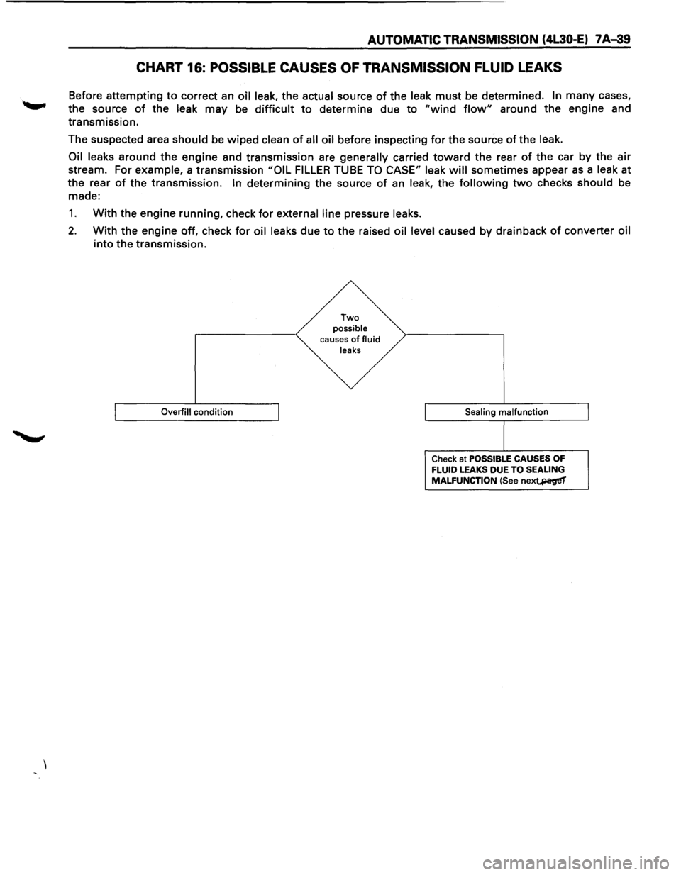
CHART 16: POSSIBLE CAUSES OF TRANSMISSION FLUID LEAKS
Before attempting to correct an oil leak, the actual source of the leak must be determined. In many cases,
the source
of the leak may be difficult to determine due to "wind flow" around the engine and
transmission.
The suspected area
should be wiped clean of all oil before inspecting for the source of the leak.
Oil leaks
around the engine and transmission are generally carried toward the rear of the car by the air
stream. For example, a transmission "OIL FILLER TUBE TO CASE" leak will sometimes appear as a leak at
the rear
of the transmission. In determining the source of an leak, the following two checks should be
made:
1. With the engine running, check for external line pressure leaks.
2. With the engine off, check for oil leaks due to the raised oil level caused by drainback of converter oil
into the transmission.
Overfill condition
Two possible causes of fluid
leaks
Sealing
malfunction
Check at POSSIBLE CAUSES OF FLUID LEAKS DUE TO SEALING
MALFUNCTION (See nex~
Page 1027 of 1928
... ......,.
AUTOMATIC TRANSMISSION (4L30-E) 7A-155
ON-VEHICLE SERVICE
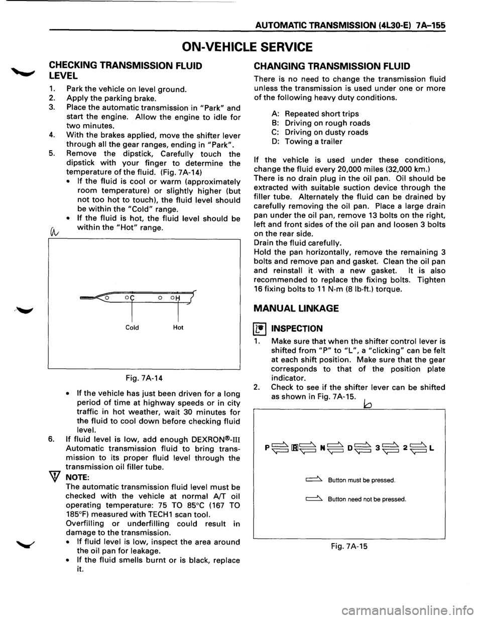
CHECKING TRANSMISSION FLUID
LEVEL
1. Park the vehicle on level ground.
2. Apply the parking brake.
3. Place the automatic transmission in "Park" and
start the engine.
Allow the engine to idle for
two minutes.
4. With the brakes applied, move the shifter lever
through all the gear ranges, ending in "Park".
5. Remove the dipstick, Carefully touch the
dipstick with your finger to determine the
temperature of the fluid. (Fig. 7A-14)
• If the fluid is cool or warm (approximately
room temperature) or slightly higher (but
not too hot to touch), the fluid level should
be within the "Cold" range.
• If the fluid is hot, the fluid level should be
(A; within the "Hot" range.
6.
Cold Hot
Fig. 7A-14
• If the vehicle has just been driven for a long
period of time at highway speeds or in city
traffic in hot weather, wait 30 minutes for
the fluid to cool down before checking fluid
level.
If fluid level is low, add enough DEXRON®-m
Automatic transmission fluid to bring trans
mission
to its proper fluid level through the
transmission oil filler tube.
NOTE:
The automatic transmission fluid level must be
checked
with the vehicle at normal AfT oil
operating temperature: 75 TO 85°C (167 TO
185°F)
measured with TECH1 scan tool.
Overfilling or underfilling could result in
damage
to the transmission.
• If fluid level is low, inspect the area around
the oil pan for leakage.
•
If the fluid smells burnt or is black, replace
it.
CHANGING TRANSMISSION FLUID
There is no need to change the transmission fluid
unless the transmission is used under one or more
of the following heavy duty conditions.
A: Repeated
short trips
B: Driving on rough roads
C: Driving on dusty roads
D: Towing a trailer
If the vehicle is used under these conditions,
change the fluid every 20,000 miles (32,000 km.)
There is
no drain plug in the oil pan. Oil should be
extracted
with suitable suction device through the
filler tube. Alternately the fluid can be drained by
carefully removing the oil pan. Place a large drain
pan
under the oil pan, remove 13 bolts on the right,
left and front sides of the oil pan and loosen 3 bolts
on the rear side.
Drain
the fluid carefully.
Hold
the pan horizontally, remove the remaining 3
bolts and remove pan and gasket. Clean the oil pan
and
reinstall it . with a new gasket. It is also
recommended to replace the fixing bolts. Tighten
16 fixing bolts to 11 N·m (8 lb·ft.) torque.
MANUAL LINKAGE
~ INSPECTION
1. Make sure that when the shifter control lever is
shifted
from "P" to "L", a "clicking" can be felt
at each shift position. Make sure that the gear
corresponds
to that of the position plate
indicator.
2. Check to see if the shifter lever can be shifted
as
shown in Fig. 7A-15. jQ
~ Button must be pressed.
~ Button need not be pressed.
Fig. 7A-15
Page 1054 of 1928
7A-182 AUTOMATIC TRANSMISSION (4l30-E)
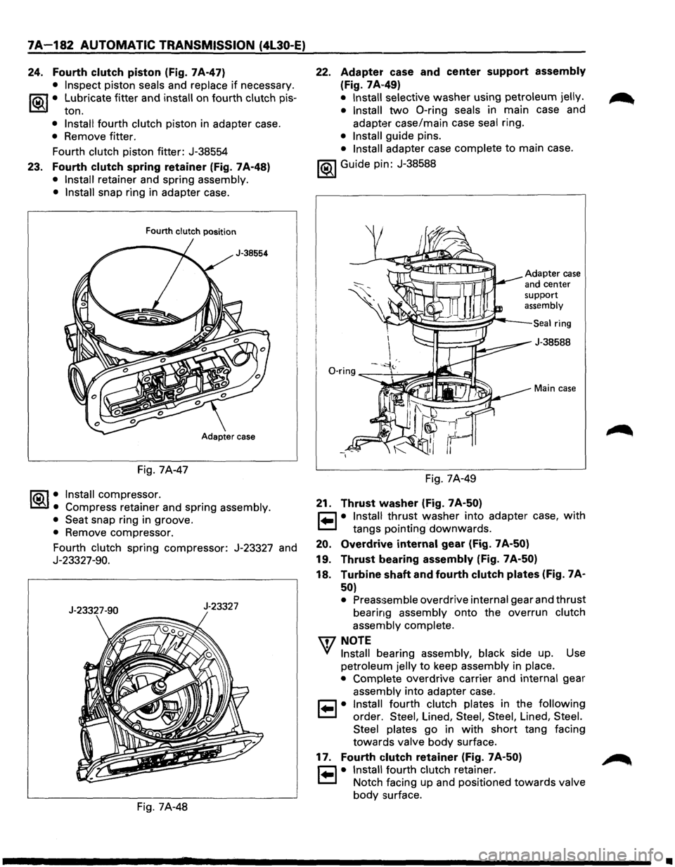
24. Fourth clutch piston (Fig. 7A-47)
• Inspect piston seals and replace if necessary.
1®-f• Lubricate fitter and install on fourth clutch pis-
ton.
• Install fourth clutch piston in adapter case.
• Remove fitter.
Fourth
clutch piston fitter: J-38554
23. Fourth clutch spring retainer (Fig. 7A-48)
• Install retainer and spring assembly.
• Install snap ring in adapter case.
Fourth clutch position
Fig. 7A-47
1®-1•. Install compressor.
Compress retainer and spring assembly.
• Seat snap ring in groove.
• Remove compressor.
Fourth
clutch spring compressor: J-23327 and
J-23327-90.
J-23327-90 J-23327
Fig. 7A-48
22.
Adapter case and center support assembly
(Fig. 7A .. 49)
• Install selective washer using petroleum jelly.
• Install
two 0-ring seals in main case and
adapter case/main case seal ring.
• Install guide pins.
• Install adapter case complete to main case.
1®1 Guide pin: J-38588
Adapter case
and center support assembly
~~§~~~r---Seal ring
-,
Fig. 7A-49
21. Thrust washer (Fig. 7 A-50)
J-38588
Main case
c::J • Install thrust washer into adapter case, with
~ tangs pointing downwards.
20. Overdrive internal gear (Fig. 7A-50)
19. Thrust bearing assembly (Fig. 7A-50)
18. Turbine shaft and fourth clutch plates (Fig. 7A·
50)
• Preassemble overdrive internal gear and thrust
bearing assembly onto the overrun clutch
assembly complete.
\f!NOTE
Yl Install bearing assembly, black side up. Use
petroleum
jelly to keep assembly in place.
• Complete overdrive carrier and internal gear
assembly into adapter case.
1•1• Install fourth clutch plates in the following
order. Steel, Lined, Steel, Steel, Lined, Steel.
Steel plates
go in with short tang facing
towards valve body surface.
17. Fourth clutch retainer (Fig. 7A-50) ~
1•1• Install fourth clutch retainer.
Notch facing up and positioned towards valve
body surface.
•
Page 1057 of 1928
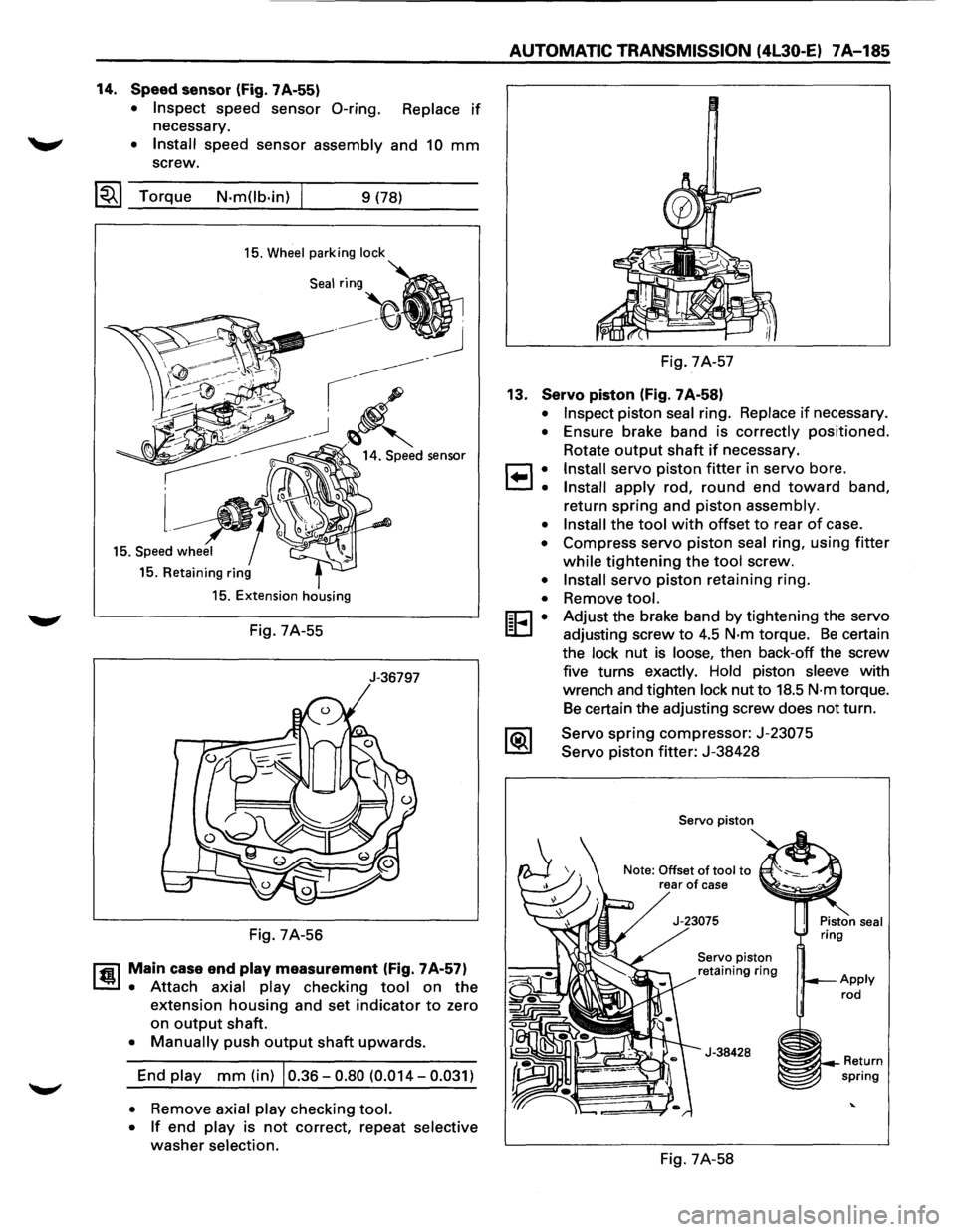
14. Speed sensor (Fig. 7A-55)
• Inspect speed sensor 0-ring. Replace if
necessary.
~ • Install speed sensor assembly and 10 mm
screw.
~~~ Torque N-m(lb-in) 9 (78)
15. Wheel parking lock
15. Retaining ring
15. Extension housing
Fig. 7A-55
J-36797
Fig. 7A-56
rfil Main case end play measurement (Fig. 7A-57)
~ • Attach axial play checking tool on the
extension housing and set indicator to zero
on
output shaft.
• Manually push output shaft upwards.
End play mm (in) 10.36-0.80 (0.014-0.031)
• Remove axial play checking tool.
• If end play is not correct, repeat selective
washer selection.
AUTOMATIC TRANSMISSION (4l30-E) 7A-185
Fig. 7A-57
13. Servo piston (Fig. 7A-58)
•
•
8:
•
•
•
•
[E•
Inspect piston seal ring. Replace if necessary .
Ensure brake band is correctly
positioned .
Rotate
output shaft if necessary.
Install servo piston fitter in servo bore.
Install apply rod, round end toward band,
return
spring and piston assembly.
Install the tool with offset to rear of case .
Compress servo
piston seal ring, using fitter
while tightening the tool screw.
Install servo piston retaining ring .
Remove
tool.
Adjust the brake band by tightening the servo
adjusting screw
to 4.5 N-m torque. Be certain
the lock nut
is loose, then back-off the screw
five turns exactly. Hold piston sleeve with
wrench and tighten lock nut to
18.5 N-m torque.
Be certain the adjusting screw does not turn.
Servo
spring compressor: J-23075
Servo piston fitter: J-38428
Servo piston
Note: Offset
of tool to rear of case
Servo piston
retaining ring
J-38428
Fig. 7A-58
~~--Return spring
Page 1066 of 1928
7A-194 AUTOMATIC TRANSMISSION (4L30-E)
f•!•l REASSEMBLY
15. Force motor screen assembly
14. Plug
13. 0-ring
12. Spring pin
11. Feed
limit valve
10. Retaining ring
9. Spring
8. Spring pin
7. 3/4 accumulator control valve
6. 3/4 accumulator valve
5. Plug
4. Spring pin
3. Force motor solenoid
2. Retainer
r=1 • Plac_e solenoid terminals pointing towards
1=.1 matmg face.
• Install retainer and bolt.
~~~ Torque N·m (lb·in) I 10 (87)
1. Converter clutch solenoid
• Install converter clutch solenoid assembly with
two 0-rings to valve body.
• Install bolt.
~~~ Torque N·m (lb·in) I 10 (87)
Page 1069 of 1928
l•!•l DISASSEMBLY
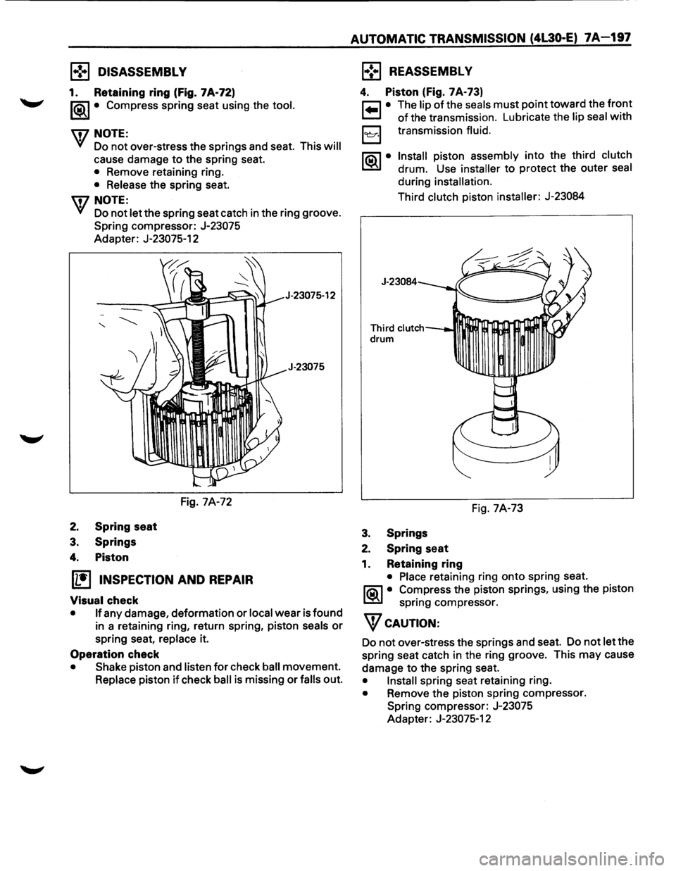
1. Retaining ring (Fig. 7A·72)
1®.1• Compress spring seat using the tool.
U7 NOTE:
VI Do not over-stress the springs and seat. This will
cause damage to the spring seat.
• Remove retaining ring.
• Release the spring seat.
U7 NOTE:
VI Do not let the spring seat catch in the ring groove.
Spring compressor: J-23075
Adapter: J-23075-12
Fig. 7A-72
2. Spring seat
3. Springs
4. Piston
~ INSPECTION AND REPAIR
Visual check
J-23075-12
J-23075
• If any damage, deformation or local wear is found
in a retaining ring, return spring, piston
seals or
spring seat, replace it.
Operation check
• Shake piston and listen for check ball movement.
Replace piston if check ball is missing or falls out.
AUTOMATIC TRANSMISSION (4L30-E) 7A-197
l•!•l REASSEMBLY
4. Piston (Fig. 7A·73)
r=1 • The lip of the seals must point toward the front
t=J of the transmission. Lubricate the lip seal with
loe:r·l transmission fluid.
~·
Install piston assembly into the third clutch
drum. Use installer to protect the outer seal
during installation.
Third clutch piston installer: J-23084
J-23084
Third clutch----•n drum
Fig. 7A-73
3. Springs
2. Spring seat
1. Retaining ring
• Place retaining ring onto spring seat.
~ • Co~press the piston springs, using the piston
sprmg compressor.
WcAUTION:
Do not over-stress the springs and seat. Do not let the
spring seat catch in the ring groove. This may cause
damage to the spring seat.
• Install spring seat retaining ring.
• Remove the piston spring compressor.
Spring compressor: J-23075
Adapter: J-23075-12
Page 1070 of 1928
7A-198 AUTOMATIC TRANSMISSION (4L30-E)
SPRAG UNIT
2. Sprag assembly
3. Sun gear assembly
Fig. 7A-74
1.,!•1 DISASSEMBLY
1. Sprag outer race
2.
Sprag assembly
• Remove sprag outer race and sprag assembly
from third clutch hub and sun gear assembly.
3. Sun gear assembly
(1!] INSPECTION AND REPAIR
Visual check
• If any damage, deformation or local wear is found
in a sun gear, sprag assembly or sprag outer race,
replace it.
1•! .. 1 REASSEMBLY
3. Sun gear assembly
2. Sprag assembly
• Install sprag assembly onto the sun gear.
\fl NOTE:
VI Flared shoulder of the sprag cage faces the sun
gear.
This procedure
must be followed exactly to be
sure that the sprag assembly is
installed properly.
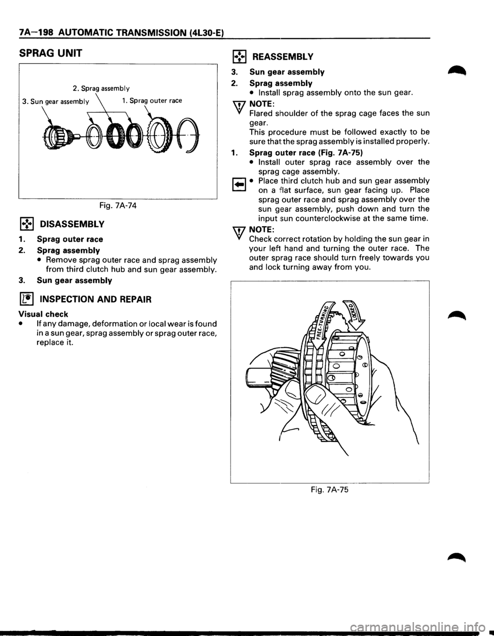
1. Sprag outer race (Fig. 7A-75)
• Install outer sprag race assembly over the
sprag cage assembly.
1•1• Place third clutch hub and sun gear assembly
on a
1Fiat surface, sun gear facing up. Place
sprag outer race and sprag assembly over the
sun
g,ear assembly, push down and turn the
input sun counterclockwise at the same time.
\fl NOTE:
VI Check correct rotation by holding the sun gear in
your left hand and turning the outer race. The
outer sprag race should turn freely
towards you
and
lock turning away from you.
Fig. 7A-75
•