tow ISUZU TROOPER 1995 Owner's Manual
[x] Cancel search | Manufacturer: ISUZU, Model Year: 1995, Model line: TROOPER, Model: ISUZU TROOPER 1995Pages: 1928
Page 727 of 1928
DRIVEABILITV AND EMISSIONS 6E2-31
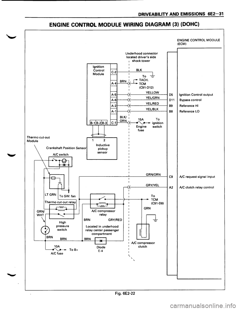
ENGINE CONTROL MODULE WIRING DIAGRAM (3) (DOHC)
Thermo cut-out Module Ignition
Control
Module
J
Underhood connector located driver's side 1 shock tower I
~r---~: ___ B~L=K~--~
I-: To -d::-1--A-4 I-
BRN I, r--TACH. \~TCM I (C91-D12) I
~1-----\(. f-------...:.Y.=.E:::LL:.:O:..:W:..:._--1 OS
~L-----'~
11---\-{' t----Y:..::E~LJ:..:::B.:::LK~--l BB f.---I BLK/ I f.---ORN 15A To C-1 "\~ ignition
Engine switch
fuse
2
Inductive pickup
sensor
Crankshaft
Position Sensor
NC switch
I ~~ l '--------J
\'r-----.
High
BRN
BRN
]_OA ~ ToB+ A/C fuse
BRN
NC compressor relay
GRY/RED
Located in underhood relay center passenger compartment
BRN I I I "' I
Diode E-4
I
I
-<( ,1,
I
I
GRN/ORN
GRY!YEL
To
TCM (C91-D8l
GRN
n
l
NC compressor clutch
' '
Fig. 6E2-22
C9
A2
ENGINE CONTROL MODULE (ECM)
Ignition Control output
Bypass control
Reference HI
Reference LO
NC request signal input
NC clutch relay control
Page 746 of 1928
6E2-50 DRIVEABILITY AND EMISSIONS
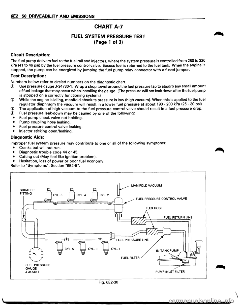
Circuit Description:
CHART A-7
FUEL SYSTEM PRESSURE TEST
(Page 1 of 3)
The fuel pump delivers fuel to the fuel rail and injectors, where the system pressure is controlled from 280 to 320
kPa (41 to 46 psi) by the fuel pressure control valve. Excess fuel is returned to the fuel tank. When the engine is
stopped, the
pump can be energized by jumping the fuel pump relay connector with a fused jumper.
Test Description:
Numbers below refer to circled numbers on the diagnostic chart.
CD Use pressure gauge J-34730-1. Wrap a shop towel around the fuel pressure tap to absorb any small amount
offuelleakage that may occur when installing the gauge. (The pressure will not leak down after the fuel pump
is stopped on a correctly functioning system.)
® While the engine is idling, manifold absolute pressure is low (high vacuum). When this is applied to the fuel
regulator
diaphragm the vacuum will result in a lower fuel pressure at about 190-200 kPa (25-30 psi)
@ The application of high vacuum to the fuel pressure control valve should result in a fuel pressure drop.
@ Fuel pressure leak-down may be caused by one of the following:
• Fuel
pump check valve not holding.
•
Pump coupling hose leaking.
• Fuel
pressure control valve leaking.
• Injector
sticking open/leaking.
Diagnostic Aids:
Improper fuel system pressure may contribute to one or all of the following symptoms:
• Cranks but will not run.
• Diagnostic trouble code 44 or 45.
• Cutting out (May feel like ignition problem).
•
Hesitation, loss of power or poor fuel economy.
Refer
to "Symptoms", Section "6E2-B".
SHRADER FITTING
FUEL PRESSURE
GAUGE
J-34730-1
Fig. 6E2-30
MANIFOLD VACUUM
FUEL PRESSURE CONTROL VALVE
FUEL RETURN LINE
FUEL FILTER
PUMP INLET FILTER
Page 751 of 1928
DRIVEABILITY AND EMISSIONS 6E2-55
CHART A-7
(Page 3 of 3)
FUEL SYSTEM PRESSURE TEST
Tools Required: J34730-1 FUEL PRESSURE GAUGE
CAUTION: TO REDUCE THE RISK OF FIRE AND PERSONAL INJURY:
• IT
IS NECESSARY TO RELIEVE FUEL SYSTEM PRESSURE BEFORE CONNECTING A FUEL
PRESSURE GAUGE.
• A SMALL AMOUNT OF FUEL MAY BE RELEASED WHEN DISCONNECTING THE FUEL LINES.
COVER FUEL l-INE FITTINGS WITH A SHOP TOWEL BEFORE DISCONNECTING, TO CATCH ANY
FUEL THATMAYLEAKOUT. PLACETOWELINAPPROVEDCONTAINERWHENDISCONNECTIS
COMPLETED.
FUEL PRESSURE
RELIEF PROCEDURE
1. REMOVE FUEL CAP.
2. REMOVE FUEL PUMP RELAY FROM UNDERHOOD RELAY CENTER.
3. START
ENGINE AND ALLOW TO STALL.
4. CRANK ENGINE FOR ADDITIONAL 30 SECONDS.
5. REMOVE NEGATIVE BATTERY CABLE.
FUEL GAUGE ADAPTER
INSTALLATION
1. REMOVE SHOULDER FITTING CAP.
2. INSTALL FUEL GAUGE J34730-1 TO FUEL RAIL
3. REINSTALL FUEL PUMP RELAY.
4. CONNECT NEGATIVE BATTERY CABLE.
5. IF YOU ARE WORKING ON A DOHC, IT WILL BE NECESSARY TO INSTALL THE INTAKE MANIFOLD RUN
PLATE.
REFER TO SECTION C2 FUEL METERING SYSTEM FOR INTAKE REMOVAL.
REFER TO INTAKE MANIFOLD DIAGNOSTIC PLATE FOR INSTALLATION INSTRUCTIONS, AS WILL AS
CHART A-8 OF THIS SECTION.
Page 789 of 1928
IGNITION SYSTEM
• CHECK: Spark plugs for proper heat cause. Refer
to Owner's Manual.
• CHECK: Ignition timing, using a "Scan tool".
ENGINE MECHANICAL
• CHECK: For excessive oil in the combustion
chamber. -
Valve oil seals for leaking.
• CHECK: Combustion chambers for excessive
carbon
build up. Remove carbon with top
engine cleaner and follow instructions on
can.
DRIVEABILITY AND EMISSIONS 6E2-93
• CHECK: Combustion chamber pressure by
performing a compression test.
See
ENGINE MECHANICAL DIAGNOSIS
(SECTION 6A).
• CHECK: For incorrect basic engine parts such as
cam, heads, pistons, etc.
HESITATION, SAG, STUMBLE
Definition: Momentary lack of response as the
accelerator is pushed down. Can occur at
all car speeds. Usually most severe when
first trying
to make the car move, as from a
stop sign. May cause engine to
stall if
severe enough.
PRELIMINARY CHECKS
• Perform the careful visual/physical checks as
described at start of "Symptoms," Section "6E2-
B."
SENSORS
• CHECK: Throttle position sensor for binding or
sticking. Voltage should increase at a
steady
rate as throttle is moved toward
Wide Open Throttle.
• CHECK: Manifold absolute pressure sensor-use
CHART C-10.
FUEL SYSTEM
• CHECK: Fuel pressure, use CHART A-7.
• CHECK: Fuel injectors are correct for vehicle.
• CHECK: Contaminated fuel.
• CHECK: Evaporative emission canister purge
system
for proper operation. Refer to
"Evaporative Emission Control System,"
Section "6E2-C3."
IGNITION SYSTEM
• CHECK: Spark plugs for being fouled, or for faulty
secondary wiring.
• CHECK: Ignition timing, using a "Scan tool".
• CHECK: Ignition system ground.
ADDITIONAL CHECKS
• CHECK: Exhaust gas recirculation operation, use
CHART
C-7.
• CHECK: Engine thermostat functioning correctly
and proper heat range.
• CHECK: Generator output voltage. Repair if less
than 9 or more than 16 volts.
CUTS OUT, MISSES
Definition: Steady pulsation or jerking that follows
engine speed, usually more pronounced
as engine load increases, not normally felt
above 1500 revolution per minute or 48
kph
(30 mile per hour). The exhaust has a
steady spitting sound at
idle or low speed.
PRELIMINARY CHECKS
• Perform the careful visual/physical checks as
described at start of "Symptoms," Section "6E2-
B."
IGNITION SYSTEM
• Check for cylinder miss by:
1. Start engine, allow engine to stabilize then
disconnect
idle air control motor. Remove
one spark
plug wire at a time, using insulated
pliers.
CAUTION: Do not perform this test for
more than 2 minutes,
as this test may
cause damage to the three
way
catalytic converter.
2. If there is a revolution per minute drop on all
cylinders (equal
to within 50 revolution per
minute), go
to "Rough, Unstable, or Incorrect
Idle, Stalling"
symptom. Reconnect idle air
control valve.
Page 800 of 1928
6E2-1 04 DRIVEABILITV AND EMISSIONS
Engine Coolant Temperature (ECT) Sensor
A "Scan tool" displays engine temperature in degrees
centigrade. After engine is started, the temperature
should rise steadily to about 90°C then stabilize when
thermostat opens. If the engine has not been run for
several hours (overnight), the engine coolant
temperature (ECT) and intake air temperature (IAT)
readings should be close to each other. A fault in the
ECT sensor circuit should set a diagnostic trouble code
(DTC) 14. The DTC charts also contain a chart to check
for sensor resistance values relative to temperature.
Intake Air Temperature (IAT) Sensor
A "Scan tool" displays temperature of the air entering
the engine and
should read close to ambient air
temperature when engine
is cold, and rise as under
hood temperature increases.
If the engine has not
been run for several hours (overnight), the IAT sensor
temperature and
ECT readings should be close to each
other. A
failure in the IAT sensor circuit should set a
DTC 23. The DTC charts also contain a chart to check
for sensor resistance values relative to temperature.
Heated Oxygen Sensor (H02S)
The "Scan tool" has several positions that will indicate
the state
of the exhaust gases, Oxygen voltage,
integrator, and block learn. See "Scan tool" position
information in
"Introduction", "Driveability and
Emission," in this section.
A
problem in the oxygen sensor circuit, or fuel system,
should set a DTC 13 (open circuit), DTC 44 (lean
indication)/DTC 45 (rich indication). Refer to
applicable chart, if any of these DTC(s) were stored in
memory.
Throttle Position (TP) Sensor
A "Scan tool" displays throttle position in volts. On 3.2L
engine, Throttle position
(TP) sensor voltage should
read below 0.85 volts, with throttle closed and ignition
"ON", or at idle. Voltage should increase at a steady
rate
as throttle is moved toward wide open throttle.
The Engine
Control Module (ECM) has the ability to
auto-zero the TP sensor voltage if it is below about 0.85
volts. This means that any voltage less than 0.85 volts
will
be determined by the ECM to be 0% throttle.
Some
"Scan tools" have the ability to read the throttle
angle and should read 0%, when the throttle is closed.
A failure in the TP sensor or circuit should set a DTC 21.
Manifold Absolute Pressure (MAP) Sensor
"Scan tool" displays manifold pressure in volts. Low
pressure (high vacuum) reads a
low voltage, while a
high pressure
(low vacuum) reads a high voltage. A
failure in the Manifold Absolute Pressure (MAP) sensor
circuit
should set a DTC 33 and using the chart will find
the cause
of the problem. A DTC 33 may be set if a
rough or unstable
idle exists. CHART C-1 D can also be
used
to check MAP sensor.
Vehicle Speed Sensor (VSS)
A "Scan tool" reading should closely match with
speedometer reading with drive wheels turning. A
failure in the vehicle speed sensor circuit should set a
DTC 24.
AIR CONDITIONING (A/C) Request Signal
When air conditioning in "ON", the "Scan tool" should
indicate air conditioning "ON".
See
"Air Conditioning Compressor Clutch Control
System",
Section "6E2-C1 0" for A/C electrical system
diagnosis.
Power Steering Pressure (PSP) Switch
A "Scan tool" should read "OFF" normally, and "ON"
with high pressure. This reading may vary with
different "Scan tools". Refer to CHART C-1 E for power
steering pressure switch diagnosis.
Crankshaft Position (CKP) Reference Signal
The ignition control module sends a signal to the ECM,
which is used to calculate proper spark advance and
fuel delivery. A "Scan tool" will read this signal and is
displayed in revolution per minute.
See "Electronic
Ignition System",
Section "6E2-C-4" for more
information on the ignition system (ignition control).
Park/Neutral Position (PNP) Switch
A "Scan tool" should read park/neutral position when
in park, or neutral, and R-D, L, when in drive or
overdrive. This reading may vary with different makes
of tools. Refer to CHART C-1 A for park/neutral position
switch diagnosis.
Knock Sensor (KS)
A "Scan tool" will indicate when the knock sensor
module signals the ECM that knock is present. See
"Knock
Sensor System," Section "6E2-C5" for further
information on the knock sensor system.
ON-VEHICLE SERVICE
ENGINE CONTROL MODULE (ECM)
The ECM is programmed from the factory and has no replaceable calibration chip.
•
Page 818 of 1928
6E2-122 DRIVEABILITV AND EMISSIONS
INDUCTION AIR CONTROL PLATE
SYSTEM
Refer to CHART C-2D to diagnose the Induction air
control plate system.
ON-VEHICLE SERVICE
FUEL PUMP RELAY
The fuel pump relay is mounted in the engine
compartment.
Other than checking for loose
connectors, the only service possible is replacement.
MUL TIPORT FUEL INJECTION
COMPONENTS
WCAUTION:
VI • To reduce the risk of fire and personal injury, it
is necessary to relieve the fuel system pressure
before servicing
fuel system components.
• After relieving system pressure, a small
amount of fuel may be released when servicing
fuel lines or connections. In order to reduce the
chance
of personal injury, cover fuel line
fittings with a shop towel before disconnecting,
to catch any
fuel that may leak out. Place the
towel in an approved container when
disconnect is completed.
Fuel Pressure Relief Procedure
1. Remove fuel cap.
2. Remove fuel pump relay from underhood relay
box.
3. Start engine and allow to stall.
4. Crank engine for additional 30 seconds.
5. Remove negative battery cable.
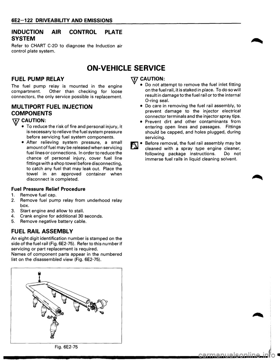
FUEL RAIL ASSEMBL V
An eight digit identification number is stamped on the
side
ofthe fuel rail (Fig. 6E2-75). Refer to this number if
servicing or part replacement is required.
Names
of component parts appear in the numbered
list on the disassembled view (Fig. 6E2-75).
'fCAUTION:
• Do not attempt to remove the fuel inlet fitting
on the
fuel rail, it is staked in place. To do so will
result
in damage to the fuel rail or to the internal
0-ring seal.
•
Do care in removing the fuel rail assembly, to
prevent damage to the injector
electrical
connector terminals and the injector spray tips.
• Prevent dirt and other contaminants from
entering open lines and passages. Fittings
should be capped, and holes plugged, during
servicing.
Before
removal, the fuel rail assembly may be
cleaned with a spray type engine cleaner,
following
package instructions. Do not
immerse fuel rails in liquid cleaning solvent.
Fig. 6E2-75
I'
---------------------'
•
Page 821 of 1928
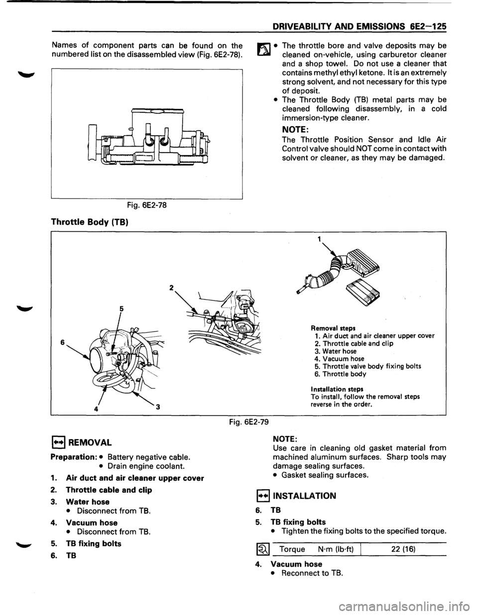
Names of component parts can be found on the
numbered
list on the disassembled view (Fig. 6E2-78).
Fig. 6E2-78
Throttle Body (TB)
5
6
2
DRIVEABILITY AND EMISSIONS 6E2-125
m • The throttle bore and valve deposits may be
t..a.l cleaned on-vehicle, using carburetor cleaner
and a shop towel. Do not use a cleaner that
contains
methyl ethyl ketone. It is an extremely
strong solvent, and
not necessary for this type
of deposit.
• The Throttle Body (TB) metal parts may be
cleaned following disassembly, in a cold
immersion-type cleaner.
NOTE:
The Throttle Position Sensor and Idle Air
Control
valve should NOT come in contact with
solvent or
cleaner, as they may be damaged.
1
Removal steps
1. Air duct and air cleaner upper cover
2.
Throttle cable and clip
3. Water hose
4. Vacuum hose
5.
Throttle valve body fixing bolts
6. Throttle body
Installation steps
To install, follow the removal steps
reverse in
the order.
Fig. 6E2-79
1••1 REMOVAL
Preparation: • Battery negative cable.
•
Drain engine coolant.
1. Air duct and air cleaner upper cover
2. Throttle cable and clip
3. Water hose
• Disconnect from TB.
4. Vacuum hose
• Disconnect from TB.
5. TB fixing bolts
6. TB
NOTE:
Use care in cleaning old gasket material from
machined
aluminum surfaces. Sharp tools may
damage
sealing surfaces.
• Gasket sealing surfaces.
I••IINSTALLATION
6. TB
5. TB fixing bolts
• Tighten the fixing bolts to the specified torque.
~~~ Torque N·m (lb·ft) 22 (16)
4. Vacuum hose
• Reconnect to TB.
Page 823 of 1928
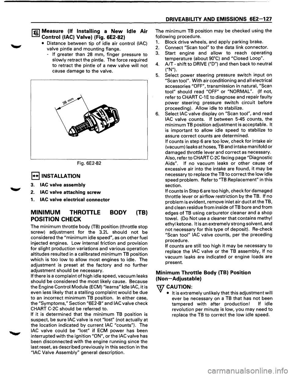
1~1 Measure (If Installing a New Idle Air
Control (lAC) Valve) (Fig. 6E2-82)
• Distance between tip of idle air control (lAC)
valve pintle and mounting flange.
-
If greater than 28 mm, finger pressure to
slowly retract the pintle. The force required
to retract the pintle
of a new valve will not
cause damage to the valve.
Fig. 6E2-82
E) INSTALLATION
3. lAC valve assembly
2. lAC valve attaching screw
1. lAC valve electrical connector
MINIMUM THROTTLE BODY (TB)
POSITION CHECK
The minimum throttle body (TB) position (throttle stop
screw) adjustment
for the 3.2L should not be
considered the
"minimum idle speed", as on other fuel
injected engines. Low internal friction and provision
for slight production variations and various operation
altitudes resulted in a calibrated
minimum TB position
which is too
low to allow most engines to idle. The
adjustment is preset at the factory and no further
adjustment should be necessary.
If there is a complaint of high idle speed, vacuum leaks
should be considered the
most likely cause. Because
the Engine
Control Module (ECM) "learns" Idle lAC, it is
even less likely
that a stalling complaint would be due
to
an incorrect minimum TB position. In either case,
the
"Symptoms," Section "6E2-B" and lAC valve check
CHART C-2C should be referred to.
If it is determined that the minimum TB position is
suspect,
be sure lAC valve is not "lost'' (not actually at
the location indicated by current
lAC "counts"). The
lAC valve could be "lost" if ECM power has been
interrupted
with the ignition "ON", or the lAC valve has
been disconnected
with the engine running since the
last reset,
as described previously in this section in the
"lAC Valve Assembly" general description.
DRIVEABILITY AND EMISSIONS 6E2-127
The minimum TB position may be checked using the
following procedure.
1. Block drive wheels, and apply parking brake.
2. Connect "Scan tool" to the data link connector.
3. Start engine and allow to reach operating
temperature (about
go•q and "Closed Loop".
4. A/T-shift to DRIVE ("D") and then back to neutral
("N").
5. Select power steering pressure switch input on
"Scan tool". With air conditioning and all electrical
accessories
"OFF", transmission in natural, "Scan
tool" should read "OFF" or "NORMAL". (If not,
refer to
CHART C-1 E to diagnose and repair faulty
power steering pressure switch circuit before
proceeding).
Allow idle to stabilize.
6. Select lAC valve display on "Scan tool", and read
lAC valve counts. If between 5-45 counts, the
minimum
TB position adjustment is acceptable. It
is important to allow idle speed to stabilize to
assure correct counts are determined.
If counts in step 6 are too low, check for intake air
(vacuum) leaks at hoses,
TB and intake manifold or
damaged throttle lever and correct as necessary.
Also, refer to
CHART C-2C facing page "Diagnostic
Aids". If no vacuum leaks or other cause of
excessive air into the intake are found, it may be
necessary
to replace the TB to correct the low idle
speed problem. Refer to
"TB Replacement" in this
section.
If counts in Step 6 are too high, check for damaged
throttle lever or airflow restriction by the
TB. If no
problem is evident, remove inlet air
duct at the TB,
and
clean residue from inside of TB bore and from
edges of TB using carburetor cleaner and a shop
towel. (Do Not use a cleaner that contains methyl
ethyl ketone.
It is an extremely strong solvent, and
not necessary for this type of deposit). Re-check
"Scan tool" lAC valve counts, per the preceding
procedure.
If counts are still too high it may be necessary to
replace the
lAC valve or the TB assembly, If no
vacuum leaks are indicated
or engine loads are
present.
Minimum Throttle Body (TB) Position
(Non-Adjustable)
\fl CAUTION:
VI • It is extremely unlikely that this adjustment will
ever be necessary on a TB that has not been
tampered
with after production! If idle
revolution per minute is low, you may need
to
replace the TB to correct the low idle speed.
Page 824 of 1928
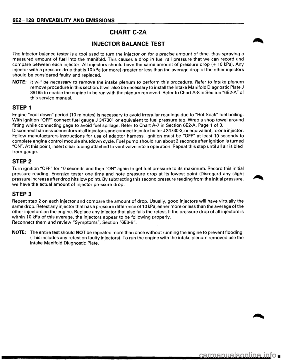
6E2-128 DRIVEABILITY AND EMISSIONS
CHART C-2A
INJECTOR BALANCE TEST
The injector balance tester is a tool used to turn the injector on for a precise amount of time, thus spraying a
measured
amount of fuel into the manifold. This causes a drop in fuel rail pressure that we can record and
compare between each injector.
All injectors should have the same amount of pressure drop (± 10 kPa). Any
injector with a pressure drop that is 10 kPa (or more) greater or less than the average drop of the other injectors
should be considered faulty and replaced.
NOTE: It will be necessary to remove the intake plenum to perform this procedure. Refer to intake plenum
remove procedure in this section. It will also be necessary to install the Intake Manifold Diagnostic Plate J
39185 to enable the engine to be run with the plenum removed. Refer to Chart A-8 in Section "6E2-A" of
this service manual.
STEP 1
Engine "cool down" period (10 minutes) is necessary to avoid irregular readings due to "Hot Soak" fuel boiling.
With ignition "OFF" connect fuel gauge J 347301 or equivalent to fuel pressure tap. Wrap a shop towel around
fitting
while connecting gage to avoid fuel spillage. Refer to Chart A-7 in Section 6E2-A, Page 1 of 3.
Disconnect harness connectors at all injectors, and connect injector tester J 34730-3, or equivalent, to one injector.
Follow manufacturers instructions for use of adaptor harness. Ignition must be "OFF" at least 10 seconds to
complete engine control module shutdown cycle. Fuel pump should run about 2 seconds after ignition is turned
"ON". At this point, insert clear tubing attached to vent valve into a operation. Repeat this step until all air is bled
from gauge.
STEP 2
Turn ignition "OFF" for 10 seconds and then "ON" again to get fuel pressure to its maximum. Record this initial
pressure reading. Energize tester one time and note pressure drop at its lowest point (Disregard any slight
pressure increase after drop hits low point). By subtracting this second pressure reading from the initial pressure, ~
we have the actual amount of injector pressure drop.
STEP 3
Repeat step 2 on each injector and compare the amount of drop. Usually, good injectors will have virtually the
same drop. Retest any injector
that has a pressure difference of 10 kPa, either more or less than the average of the
other injectors on the engine.
Replace any injector that also fails the retest. If the pressure drop of all injectors is
within 10 kPa of this average, the injectors appear to be following properly.
Reconnect them and review "Symptoms", Section "6E3-B".
NOTE: The entire test should NOT be repeated more than once without running the engine to prevent flooding.
(This includes any retest on faulty injectors). To run the engine with the intake plenum removed use the
Intake Manifold Diagnostic Plate.
•
Page 826 of 1928
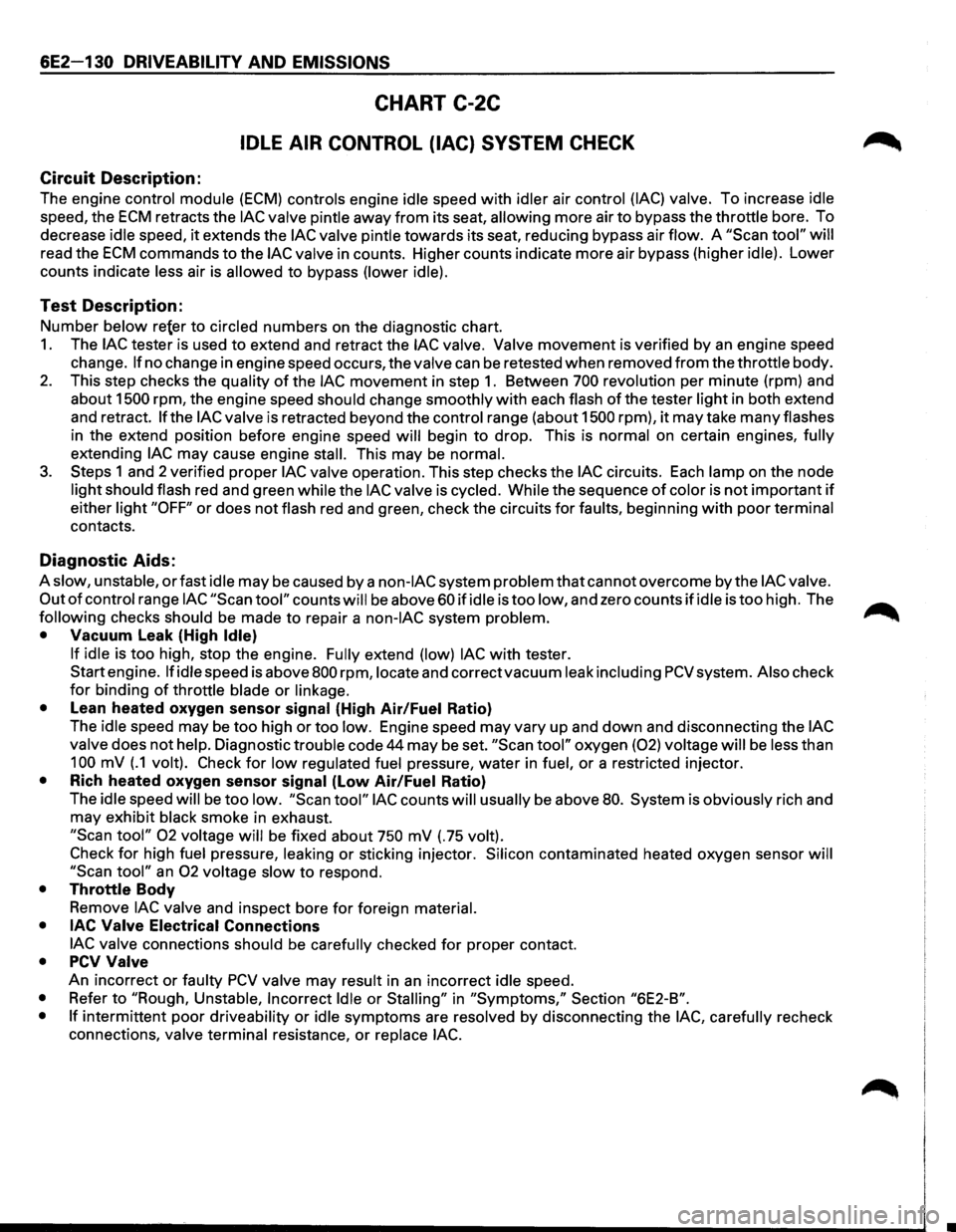
6E2-130 DRIVEABILITY AND EMISSIONS
CHART C-2C
IDLE AIR CONTROL (lAC) SYSTEM CHECK
Circuit Description:
The engine control module (ECM) controls engine idle speed with idler air control (lAC) valve. To increase idle
speed, the ECM retracts the lAC valve pintle away from its seat, allowing more air to bypass the throttle bore. To
decrease
idle speed, it extends the lAC valve pintle towards its seat, reducing bypass air flow. A "Scan tool" will
read the ECM commands to the lAC valve in counts. Higher counts indicate more air bypass (higher idle). Lower
counts indicate
less air is allowed to bypass (lower idle).
Test Description:
Number below re{er to circled numbers on the diagnostic chart.
1. The lAC tester is used to extend and retract the lAC valve. Valve movement is verified by an engine speed
change.
If no change in engine speed occurs, the valve can be retested when removed from the throttle body.
2. This step checks the quality of the lAC movement in step 1. Between 700 revolution per minute (rpm) and
about
1500 rpm, the engine speed should change smoothly with each flash of the tester light in both extend
and retract.
If the lAC valve is retracted beyond the control range (about 1500 rpm), it may take many flashes
in the extend position before engine speed will begin to drop. This is normal on certain engines, fully
extending lAC may cause engine stall. This may be normal.
3. Steps 1 and 2 verified proper lAC valve operation. This step checks the lAC circuits. Each lamp on the node
light should flash red and green while the lAC valve is cycled. While the sequence of color is not important if
either light "OFF" or does not flash red and green, check the circuits for faults, beginning with poor terminal
contacts.
Diagnostic Aids:
A slow, unstable, or fast idle may be caused by a non-lAC system problem that cannot overcome by the lAC valve.
Out
of control range lAC "Scan tool" counts will be above 60 if idle is too low, and zero counts if idle is too high. The ..-...
following checks should be made to repair a non-lAC system problem. _......._
• Vacuum Leak (High Idle)
If idle
is too high, stop the engine. Fully extend (low) lAC with tester.
Start engine.
If idle speed is above 800 rpm, locate and correct vacuum leak including PCV system. Also check
for binding of throttle blade or linkage.
•
Lean heated oxygen sensor signal (High Air/Fuel Ratio)
The
idle speed may be too high or too low. Engine speed may vary up and down and disconnecting the lAC
valve
does not help. Diagnostic trouble code 44 may be set. "Scan tool" oxygen (02) voltage will be less than
100 mV (.1 volt). Check for low regulated fuel pressure, water in fuel, or a restricted injector.
• Rich heated oxygen sensor signal (Low Air/Fuel Ratio)
The
idle speed will be too low. "Scan tool" lAC counts will usually be above 80. System is obviously rich and
may exhibit
black smoke in exhaust.
"Scan tool" 02 voltage will be fixed about 750 mV (.75 volt).
Check
for high fuel pressure, leaking or sticking injector. Silicon contaminated heated oxygen sensor will
"Scan
tool" an 02 voltage slow to respond.
• Throttle Body
Remove
lAC valve and inspect bore for foreign material.
• lAC Valve
Electrical Connections
lAC valve
connections should be carefully checked for proper contact.
• PCV Valve
An incorrect or faulty PCV valve may result in an incorrect idle speed.
• Refer to "Rough, Unstable, Incorrect Idle or Stalling" in "Symptoms," Section "6E2-B".
• If
intermittent poor driveability or idle symptoms are resolved by disconnecting the lAC, carefully recheck
connections,
valve terminal resistance, or replace lAC.