tow ISUZU TROOPER 1995 User Guide
[x] Cancel search | Manufacturer: ISUZU, Model Year: 1995, Model line: TROOPER, Model: ISUZU TROOPER 1995Pages: 1928
Page 532 of 1928
6A-16 GENERAL ENGINE MECHANICAL
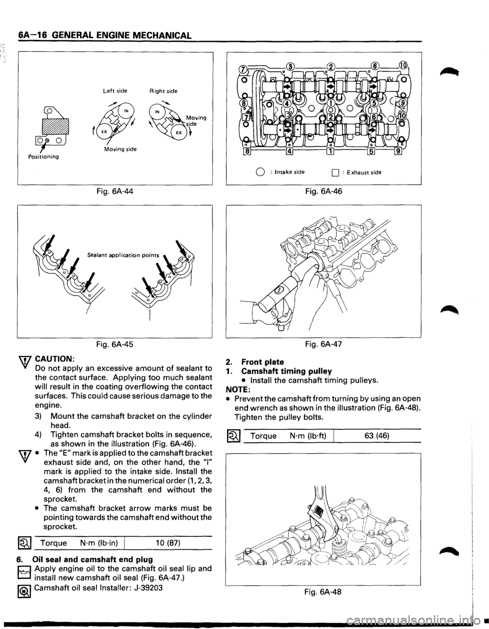
Left side Right side
Moving side Positioning
Q : Intake side 0 : Exhaust side
Fig. 6A-44 Fig. 6A-46
Sealant application points
Fig. 6A-45
7 CAUTION:
'VI Do not apply an excessive amount of sealant to
the contact surface. Applying too much sealant
will result
in the coating overflowing the contact
surfaces. This
could cause serious damage to the
engine.
3)
4)
w·
•
Mount the camshaft bracket on the cylinder
head.
Tighten camshaft bracket
bolts in sequence,
as shown in the illustration (Fig. 6A-46).
The
"E" mark is applied to the camshaft bracket
exhaust side and, on the other hand, the
"I"
mark is applied to the intake side. Install the
camshaft bracket in the
numerical order (1, 2, 3,
4, 6) from the camshaft end without the
sprocket.
The camshaft bracket
arrow marks must be
pointing towards the camshaft end
without the
sprocket.
~~~ Torque N·m (lb·in) f 10 (87)
6. Oil seal and camshaft end plug
CJ Apply engine oil to th~ camsh~ft oil seal lip and
L.::::J install new camshaft oil seal (F1g. 6A-47.)
1®..1 Camshaft oil seal Installer: J-39203
Fig. 6A-47
2. Front plate
1. Camshaft timing pulley
• Install
the camshaft timing pulleys.
NOTE:
• Prevent the camshaft from turning by using an open
end wrench
as shown in the illustration (Fig. 6A-48).
Tighten the
pulley bolts.
~~~ Torque N·m (lb·ft) 63 (46)
Fig. 6A-48
•
Page 561 of 1928
CYLINDER BLOCK
The cylinder block is made of aluminum die-cast
casting
for 75° V-type six cylinders. It has a rear plate
integrated structure and employs a deep skirt. The
cylinder liner is cast and the liner inner diameter and
crankshaft
journal diameter are classified into grades.
The crankshaft is supported by four bearings
of which
width is different between No.2, No.3 and No.1, No.4;
the
width of No.3 bearing on the body side is different
in order
to support the thrust bearing. The bearing cap
is made
of nodular cast iron and each bearing cap uses
four bolts and two side bolts.
CYLINDER HEAD
The cylinder head, made of aluminum alloy casting
employs a pent-roof type combustion chamber with a
spark
plug in the center.
The intake and exhaust
valves are placed in V-type
design. The ports are cross-flow type.
VALVE TRAIN
SOHC: The camshafts on both banks are driven by a
timing
belt to operate the valves via rocker arm.
No
further valve clearance adjustment is
required, due
to the Hydraulic lash adjuster
attachedtotherockerarm.
DOHC: Intake camshaft on the both sides of banks are
driven through a
timing belt, while exhaust
camshaft are driven by the both sides
of intake
camshaft through chains.
The driven camshafts open and
close valves
through swing arms.
Valve clearance is automatically adjusted by
means
of HLA built in the cylinder head.
INTAKE MANIFOLD
SOHC: The intake manifold system is composed ofthe
aluminum cast common chamber and intake
manifold attached with six fuel injectors.
DOHC: The intake manifold system is composed of the
aluminum cast common chamber duct having
the induction
control valve, common chamber
and intake
manifold attached with six fuel
injectors.
EXHAUST MANIFOLD
The exhaust manifold is made of nodular cast iron.
PISTONS AND CONNECTING RODS
Aluminum pistons are used after selecting the grade
that meets the cylinder bore diameter. Each piston has
two compression rings and one oil ring. The piston pin
made
of chromium steel is offset 1 mm toward the
thrust side, and the thrust pressure
of piston to the
cylinder wall varies gradually as the piston travels. The
connecting rods are made
of forged steel. The
connecting rod bearings are graded
for correct size
selection.
ENGINE (V6 3.2L DOHC AND SOHC) 6A1-3
CRANKSHAFT AND BEARINGS
The crankshaft is made of Ductile cast-iron.Pins and
journals are graded for correct size selection for their
bearing.
OIL PUMP
The trochoid-type oil pump is driven by crankshaft.
Operation and service procedures are described in this
section.
ENGINE LUBRICATION
The oil discharged by a trochoid-type oil pump driven
by the crankshaft is fed through full-flow oil filter and
engine
coolant cooled oil cooler up to the oil gallery
provided under the crankshaft bearing cap. The oil is
then
led to the crankshaft journals and cylinder head.
The crank pins are
lubricated with oil from crankshaft
journals through oil holes. Also, an oil jet is fed to each
cylinder from crankshaft journals on the connecting
rod
for piston cleaning. The oil pan flange is sealed with
liquid packing only; do not deform or damage the
flange surface during removal or installation.
Page 594 of 1928
6A1-36 ENGINE (V6 3.2L DOHC AND SOHC)
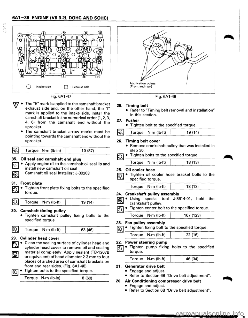
Q : Intake side 0 : Exhaust side
Fig. 6A1-47
\f7 • The "E" mark is applied to the camshaft bracket
VI exhaust side and, on the other hand, the "I"
mark is applied to the intake side. Install the
camshaft bracket in the
numerical order (1, 2, 3,
4, 6) from the camshaft end without the
sprocket.
• The camshaft bracket arrow marks must be
pointing towards the camshaft end
without the
sprocket.
~~~ Torque N·m (lb·in) 10 (87)
35. Oil seal and camshaft end plug
D • Apply engine oil to the camshaft oil seal lip and
L::J install new camshaft oil seal
1®.1 Camshaft oil seal Installer: J-39203
31. Front plate
~ • Tighten front plate fixing bolts to the specified
~ torque.
~ Torque N·m (lb·ft) 19 (14)
30. Camshaft timing pulley
• Tighten camshaft pulley fixing bolts to the
specified torque
~ Torque N·m (lb·ft) 63 (46)
29. Cylinder head cover
m • Clean the sealing surface of cylinder head and
t..al cylinder head cover to remove oil and sealing
Jail material completely. Apply sealant (T8-12078
I..:!LI or equivalent) of bead diameter 2-3 mm to four
places of arched area of camshaft brackets on
front and rear sides. (Fig. 6A1-48)
~~~ • Tighten bolts to the specified torque.
Torque
N·m (lb·in) I 8 (69)
Application points (Front and rear)
28. Timing belt
Fig. 6A1-48
• Refer to "Timing belt removal and installation"
in this section.
27. Pusher
• Tighten bolt to the specified torque.
~~~ Torque N·m (lb·ft) 19 (14)
26. Timing belt cover
• Remove crankshaft pulley that was installed in
step
30.
~~~· Tighten bolts to the specified torque.
Torque
N·m (lb·ft) I 18 (13)
25. Oil cooler hose
~ • Tighten oil cooler hose bracket bolts to the
~ specified torque.
Torque
N·m (lb·ft) 18 (13)
24. Crankshaft pulley assembly
1?.:\1 • Using special tool J-8614-01, hold the
~ crankshaft pulley.
~~~ • Tighten center bolt to the specified torque.
Torque
N·m (lb·ft) 167 (123)
23. Fan pulley assembly
~~~· Tighten fixing bolt to the specified torque.
Torque
N·m (lb·ft) J 22 (16)
22. Power steering pump
~ • Tighten pump fixing bolts to the specified
~ torque.
Torque
N·m (lb·ft) 46 (34)
21. Generator drive belt
• Engage and adjust.
• Refer to Section 68 "Drive belt adjustment".
20. Air Conditioning compressor drive belt
• Engage and adjust.
• Refer to Section 68 "Drive belt adjustment".
Page 657 of 1928
ENGINE ELECTRICAL 601-3
ON-VEHICLE SERVICE
BATTERY CHARGING
Observe the following safety precautions when
charging the battery:
1. Never attempt to charge the battery when the
fluid level is below the lower level line on the
side
of the battery. In this case, the battery
must be replaced.
2. Pay close attention to the battery during the
charging procedure.
Battery charging
should be discontinued or the
rate
of charge reduced if the battery feels hot
to the touch.
Battery charging
should be discontinued or the
rate
of charge reduced if the battery begins to
gas or spew electrolyte from the vent holes.
3. In order to more easily view the hydrometer
blue dot or ring, it may be necessary to jiggle
or tilt the battery.
4. Battery temperature can have a great effect on
battery charging capacity.
5. The sealed battery used on this vehicle may be
either quick-charged or slow-charged in the
same manner
as other batteries.
Whichever method you decide
to use, be sure
that you
completely charge the battery. Never
partially charge the battery.
JUMP STARTING
JUMP STARTING WITH AN AUXILIARY
(BOOSTER)
BATTERY
W CAUTION:
Never push or tow the vehicle in an attempt to
start it.
Serious damage to the emission sys
tem as
well as other vehicle parts will result.
Treat both the discharged battery and the
booster battery
with great care when using
jumper cables. Carefully follow the jump start
ing procedure, being
careful at all times to
avoid sparking.
wwARNING:
Failure to carefully follow the jump starting
procedure
could result in the following:
1. Serious personal injury, particulaly to your
eyes.
2. Property damage from a battery explo
sion, battery acid, or an electrical fire.
3. Damage to the electronic components of
one or both vehicles particularly.
Never expose the battery to an open flame or elec
trical
spark. Gas generated by the battery may catch
fire
or explode.
Remove any rings, watches, or other jewelry before
working around the battery. Protect
your eyes by
wearing
an approved set of goggles.
Never allow battery fluid to come in contact with
your eyes or skin.
Never
allow battery fluid to come in contact with
fabrics or painted surfaces.
Battery
fluid is a highly corrosive acid.
Should battery fluid come in contact with your eyes,
skin, fabric, or a painted surface,
immediately and
thoroughly rinse the affected area with clean tap
water. Never
allow metal tools or jumper cables to come
in contact with the positive battery
terminal, or any
other
metal surface of the vehicle. This will protect
against a short circuit.
Always keep batteries out of the reach of young
children.
JUMP STARTING PROCEDURE
1. Set the vehicle parking brake.
If the vehicle is equipped with an automatic
transmission,
place the selector lever in the
"PARK" position.
If the vehicle is equipped with a manual trans
mission
place the shift lever in the "NEUTRAL"
position.
Turn
"OFF" the ignition.
Turn
"OFF" all lights and any other accessory
requiring
electrical power.
2. Look at the built-in hydrometer.
If the indication area of the built-in hydrometer
is
completely clear, do not try to jump start.
3. Attach the end of one jumper cable to the posi
tive
terminal of the booster battery.
Attach the other end
of the same cable to the
positive
terminal of the discharged battery.
Do not allow the vehicles to touch each other.
This
will cause a ground connection, effectively
neutralizing
the charging procedure.
Be sure that the booster battery has a 12 volt
rating.
4. Attach one end of the remaining cable to the
negative
terminal of the booster battery.
Attach the other end
of the same cable to a
solid engine ground (such as the air condition
ing compressor bracket or the generator
mounting bracket)
of the vehicle with the dis
charged battery.
This ground connection must be at
least 450
mm (18 in) from the battery of the vehicle
whose battery is being charged.
Page 666 of 1928
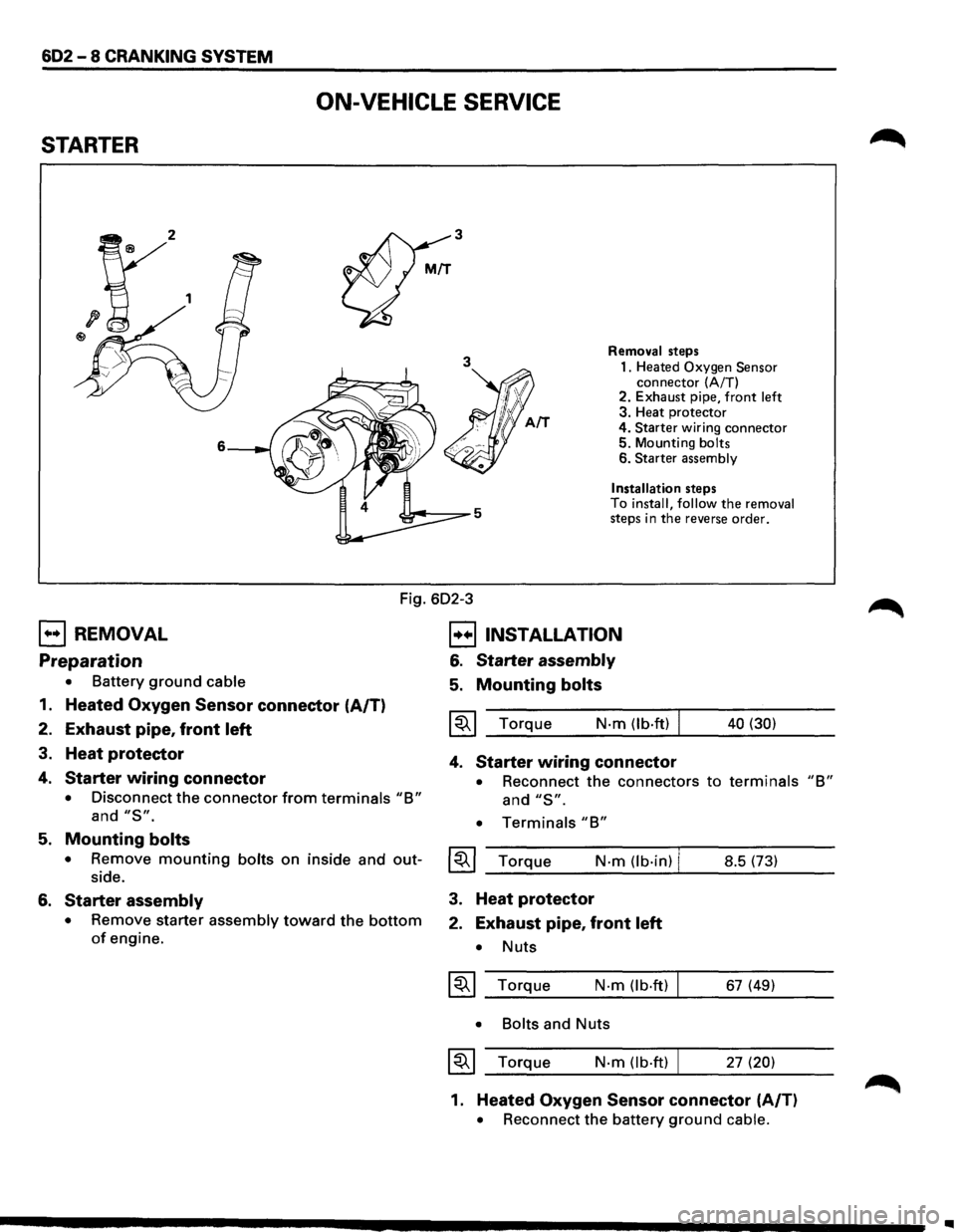
602-8 CRANKING SYSTEM
ON-VEHICLE SERVICE
STARTER
3
3
6
Removal steps
1. Heated
Oxygen Sensor connector (A/T)
2. Exhaust pipe, front left 3. Heat protector
4.
Starter wiring connector 5. Mounting bolts 6. Starter assembly
Installation
steps
To install, follow the removal steps in the reverse order.
Fig. 602-3
EJ REMOVAL
Preparation
• Battery ground cable
1. Heated Oxygen Sensor connector (A/T)
2. Exhaust pipe, front left
3. Heat protector
4. Starter wiring connector
• Disconnect the connector from terminals "B"
and "S".
B INSTALLATION
6. Starter assembly
5. Mounting bolts
~~~ Torque N·m (lb·ft) I
4. Starter wiring connector
40 (30)
• Reconnect the connectors to terminals "B"
and "S".
• Terminals "B"
5. Mounting bolts
• Remove mounting bolts on inside and out-~~~ Torque N·m (lb·in) I side. __ _;_ ______ -J.... ______ _ 8.5 (73)
6. Starter assembly
• Remove starter assembly toward the bottom
of engine.
3. Heat protector
2. Exhaust pipe, front left
• Nuts
~~~ Torque N·m (lb.ft)
• Bolts
and Nuts
~~~ Torque N·m (lb·ft) I
67 (49)
27
(20)
1. Heated Oxygen Sensor connector (A/T)
• Reconnect the battery ground cable.
..
Page 670 of 1928
602 -12 CRANKING SYSTEM
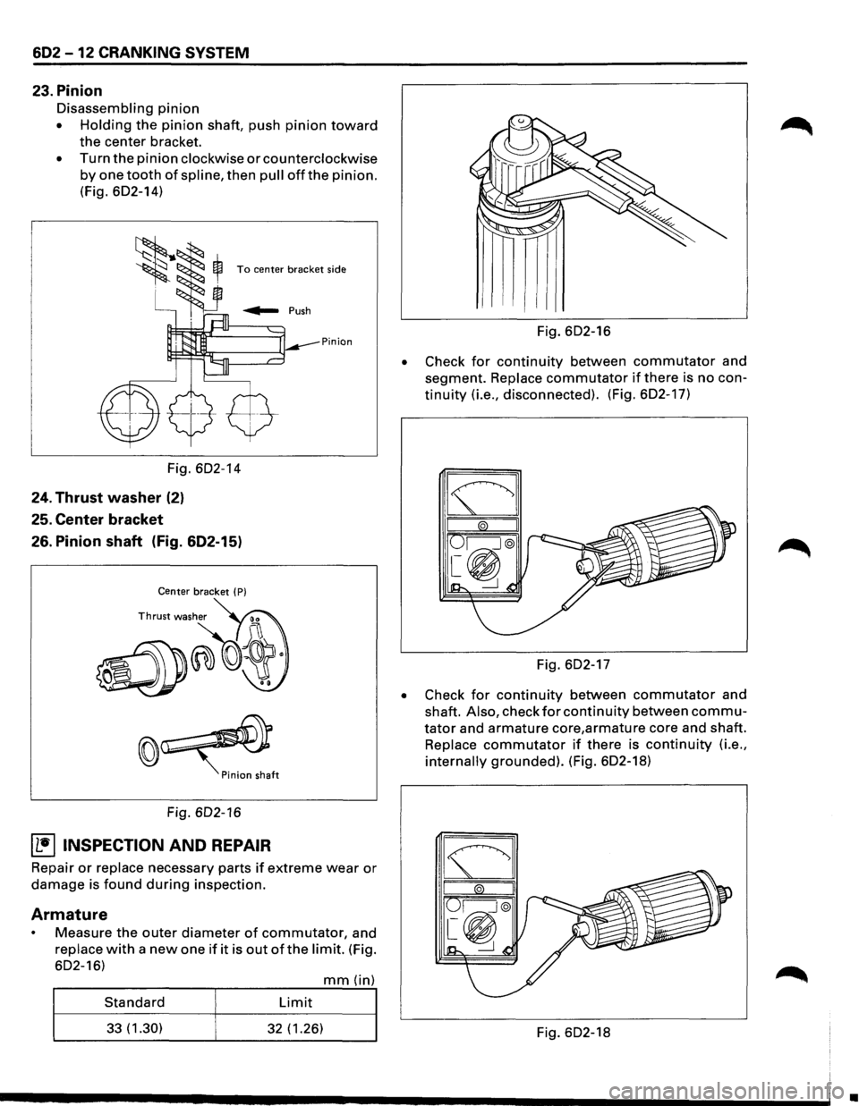
23. Pinion
Disassembling pinion
• Holding the pinion shaft, push pinion toward
the center bracket.
• Turn the pinion clockwise or counterclockwise
by one tooth of spline, then pull offthe pinion.
(Fig. 602-14)
To center bracket side
Pinion
Fig. 602-14
24. Thrust washer (2)
25. Center bracket
26. Pinion shaft (Fig. 602-15)
Center bracket ( P)
Fig. 602-16
~ INSPECTION AND REPAIR
Repair or replace necessary parts if extreme wear or
damage is found during inspection.
Armature
Measure the outer diameter of commutator, and
replace with a new one if it is out of the limit. (Fig.
602-16)
mm(in)
Standard Limit
33(1.30) 32 (1.26)
•
Fig. 602-16
Check
for continuity between commutator and
segment.
Replace commutator if there is no con
tinuity (i.e., disconnected). (Fig. 602-17)
Fig. 602-17
• Check for continuity between commutator and
shaft.
Also, check for continuity between commu
tator and armature core,armature core and shaft.
Replace commutator if there is continuity (i.e.,
internally grounded). (Fig. 602-18)
Fig. 602-18
•
Page 722 of 1928
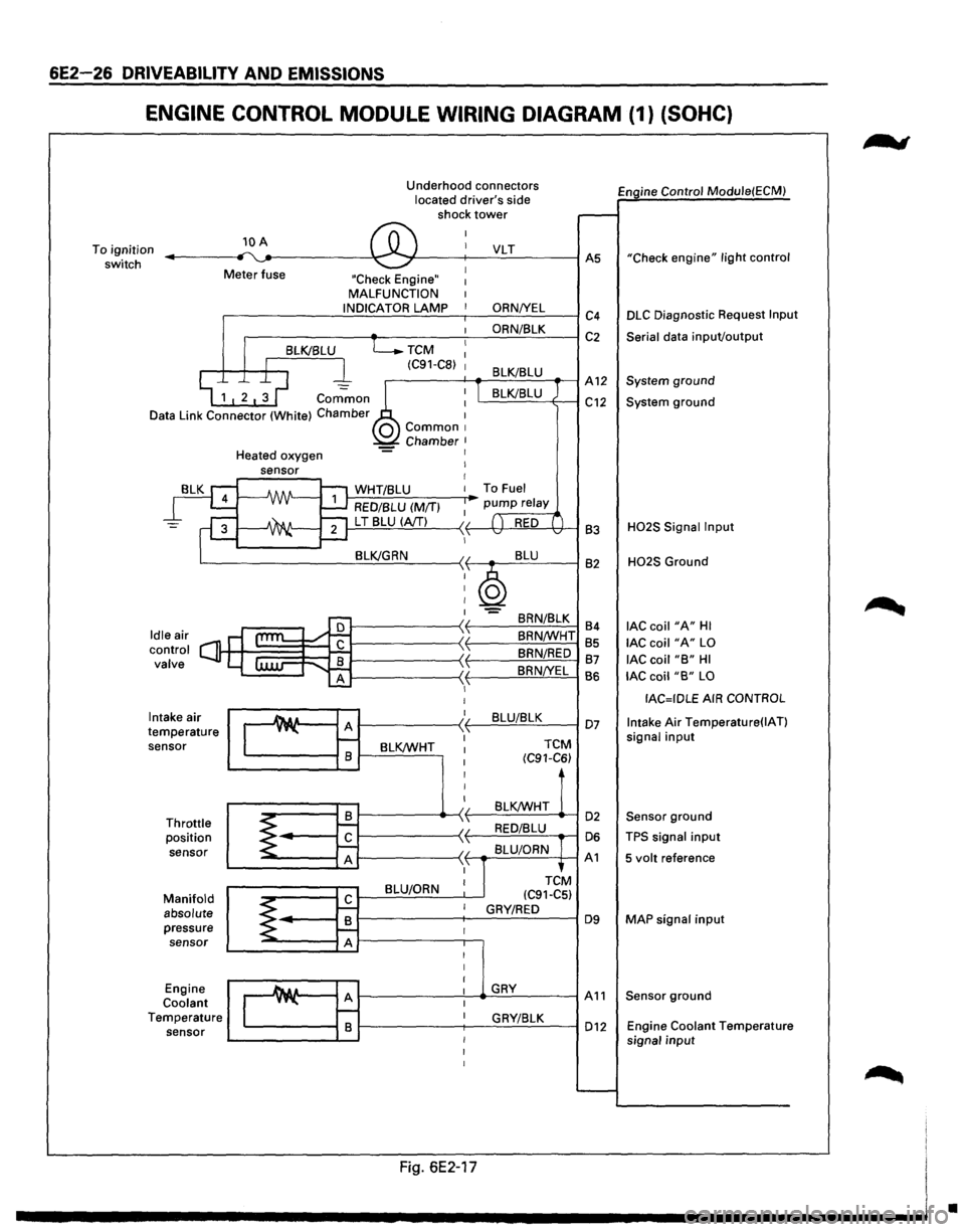
6E2-26 DRIVEABILITV AND EMISSIONS
ENGINE CONTROL MODULE WIRING DIAGRAM (1) (SOHC}
To ignition
switch 10 A
Meter fuse Underhood
connectors
located driver's side
shock tower
"Check Engine" MALFUNCTION
.-----------..:.:.1 N.:.:D:..:.IC=A~T~O:..:.R.:....=:.LA..::.M.:..::P:..___-,--___.:O:..:.R.:.:.N::.._IY.....:E:..:L=----1 c4
.------~~----~~O:..:R:..:N/~8~L=-=K--~ C 2
TCM
(C91-C8)
Engine Control Module(ECM)
"Check
engine" light control
DLC Diagnostic Request Input
Serial
data inpuVoutput
.--------f---+-....::...::;_;__=---_-1 A 12 System ground
Common
Data Link Connector (White) Chamber L.....::.=::....=..:=-=----+---1 C12 System ground
Intake air
temperature sensor
Throttle position
sensor
Manifold absolute pressure sensor
Engine
Coolant Temperature sensor Heated
oxygen
J-,.:..:W:.:..H.:..:T.:.:I8:..:L:.:U:......__ __ ....-To Fuel
RED/BLU (M/T)
1---=-'L T'-.!8~L:!:U'--l(.::::A/T!....!...!....) ---< f------lt+-~!,!..._'H---1 83
BRN/8LK
84
8RN/WHT 85
BRN/RED 87
8RN!YEL
BS
1---------~~~B~L~U~/8~L~K~--I 07
BLK/WHT
TCM
(C91-C6)
BLK/WHT 1------------4>---< t-----=~:..:.:..:_.:..:_ ....... -1 02
1-----------~ f----'-=-'-==--....-1 06
1-----------~ f--.-::..:=.=.:....=..c~-+--1 A 1
BLU/ORN
H02S Signal Input
H02S Ground
lAC coil "A" HI
lAC coil "A" LO
lAC coil "B" HI
lAC coil "B" LO
IAC=IDLE AIR CONTROL
Intake
Air Temperature(IAT)
signal input
Sensor ground
TPS signal input
5 volt reference
MAP
signal input
1---------'----...._.G:=.:..:.RY-=--------1 A 11 Sensor ground
1-------;---.:::G:..:R_;_YI:...::8:..:L::..:K:__---I 012 Engine Coolant Temperature
signal input
Fig. 6E2-17
•
Page 724 of 1928
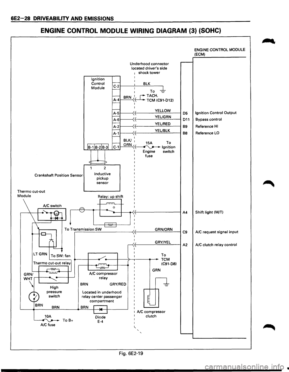
6E2-28 DRIVEABILITV AND EMISSIONS
ENGINE CONTROL MODULE WIRING DIAGRAM (3) (SOHC)
Ignition Control
Module Underhood
connector
located driver's side
1 shock tower I I 1:-2~--~~--~B~L~K~--~
- : To -4-
-BRN 1. r--TACH.
A-4 ~ TCM IC91-D12) -I
I
YELLOW
·~ YEL!GRN \ VEL/RED YEL!BLK
I--B-1IB-2IB-3l C-1
l
1 2
Crankshaft Position Sensor Inductive pickup
sensor I
I
I
I
Thermo cut-out I
I
I
I
I
n I
Mo\\I•Silj ~~
To Transmission SW ~ r-------------------~ -
'---<
LT GRN To SW: fan
Thermo cut-out relay'
GRN/
WHT
....--+-----~
BRN
High
pressure switch
BRN
NC compressor relay
BRN GRY/RED
Located in underhood relay center passenger
compartment
BRN r::-1
I
I
r
I
I
I
I
I
I
I
I
I
I
I
I
I
I
GRN/ORN
GRY!YEL To
TCM IC91-D8)
GRN
n
l
I I 1 NC compressor 10A ~ToB+ NCfuse
Diode E-4
I clutch I
I
' ' '
Fig. 6E2-19
A4
C9
A2
~
ENGINE CONTROL MODULE (ECM)
Reference HI
Reference LO
Shift light (MfT)
NC request signal input
NC clutch relay control
..
Page 725 of 1928
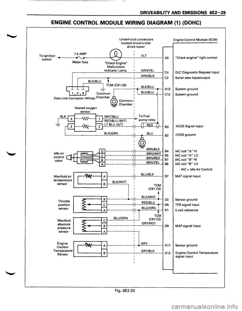
DRIVEABILITY AND EMISSIONS 6E2-29
ENGINE CONTROL MODULE WIRING DIAGRAM (1) (DOHC)
Underhood connectors
located driver's side
shock
tower
To ignition
switch 7.5AMP ,.... ~ ®
I
I
Meter fuse I "Check Engine" I Malfunction I Indicator Lamp I
I
'
I 8LK/8LU I
D
I l TCM (C91-C8) 1
~ 1 2 ~ ~ co.;;mo~~ : ata Link Connector (White) Chamber 1 0 Common1 Chamber 1 Heated oxygen -= I
rg
=F
leair s ontrol C] alve
ld c v
M
te anifold
air
mperature sensor
Throttle position sensor
Manifold absolute pressure sensor
Engine
Coolant
T emperature
Sensor
sensor I
I
-A/IN-1:'1 WHT/8LU I
~ RED/8LU (M/TI I
~ ""21 L T 8LU (A/TI II ....::....1 ,1,
8LK/GRN :,
I
I
I
I
cam l:
I
I
Au A )I y"-\1 r--
8 8LK/WHT I I
I
I
I
8 ~ 1--II
~ r£ \ 'I A ,1,
8LU/ORN I
r£ ~ I
8 ~ f--I A I
I
I
_A& a A I y"-I r--I 8 I
I
I
Fig. 6E2-20
VLT
ORNNEL
ORN/8LK
8LK/8LU
I 8LK/8LU
To Fuel
pump relay
( ) RED ( v v
8LU
~ -8RN/8LK
8RN/WHT
8RN/RED
8RNNEL
8LU/8LK
TCM (C91-C6)
8LK/WHT !
RED/8LU
8LU/ORN
TCtM
(C91-C5)
GRY/RED
GRY
GRY/8LK Engine
Control
Module (ECMI
.-----
AS "Check engine" light control
C4 DLC Diagnostic Request lnpu
C2 Serial data input/output
A12 System ground
C12 System ground
83
H02S Signal input
82 H02S ground
84
lAC coil "A" HI
85 lAC coil "A" LO
87 lAC coil "8" HI
86 lAC coil "8" LO
lAC = Idle Air Control
D7 MAT signal input
D2 Sensor ground
D6 TPS signal input
A1 5 volt reference
D9 MAP signal input
A11 Sensor ground
D12 Engine Coolant Temperatur e signal input
......__
Page 726 of 1928
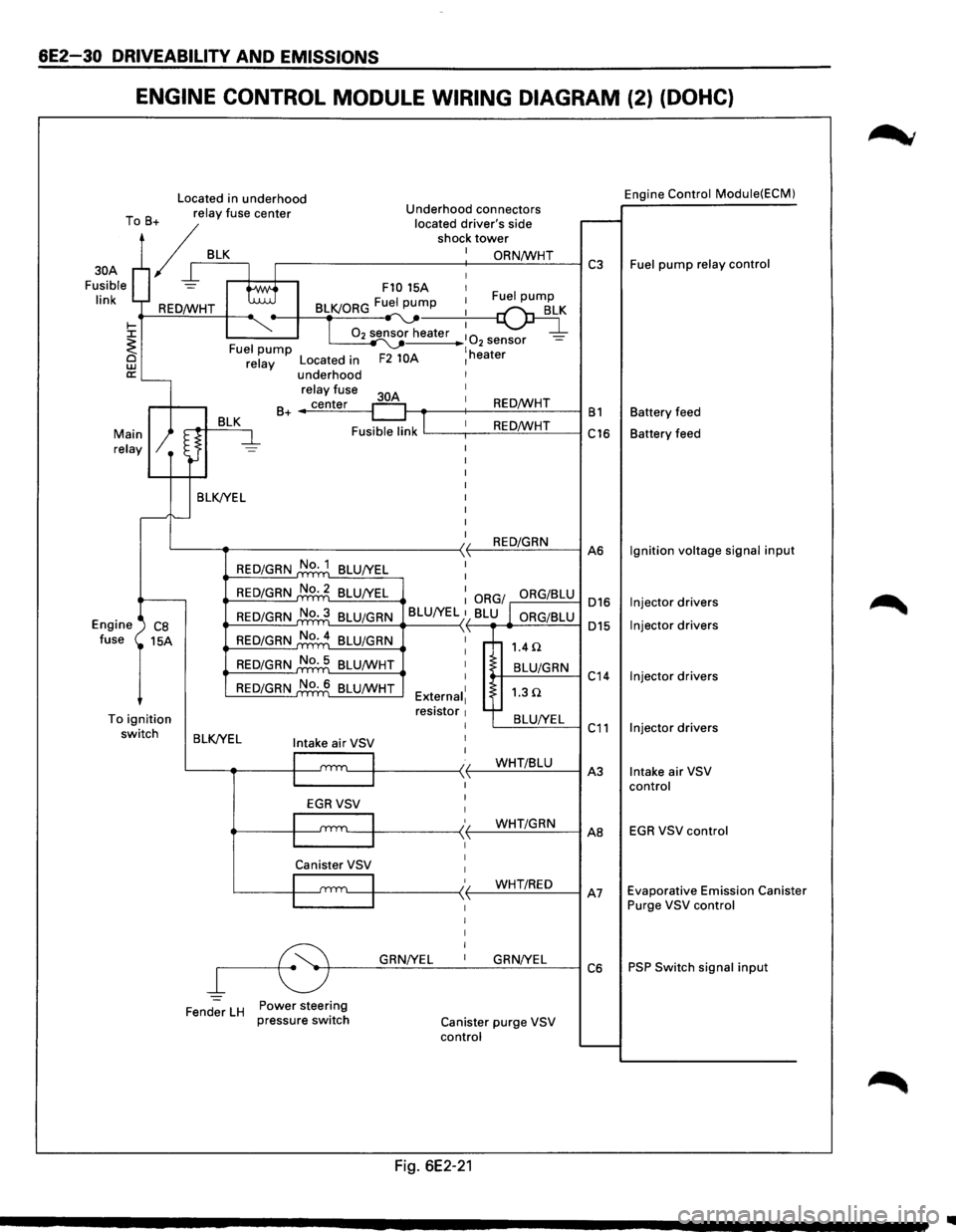
6E2-30 DRIVEABILITY AND EMISSIONS
ENGINE CONTROL MODULE WIRING DIAGRAM (2) (DOHC)
Located in underhood Engine Control Module(ECM)
T B relay
fuse center Underhood connectors
o + located
driver's side r--. / shock tower
/ I BLK.---+-I_: ~==-----------+-: __ O_R_N...:./W_H_T_--1 C3 Fuel pump relay control
Fusible
= tti F10 15A 1
30A
I' k I 1 Fuel pump In REO/WHT BLK/ORG Fu:.._pu~
~ ~-T 02 sensor heater :
0 _ ~ I ~ 2 sensor -<. Fuel pump ~ lh @ relay Located in F2 10A 1 eater
a:'---underhood
relay fuse I
BLK 30A
1 B+ _..;c:..::ec:..:n-=.:te:.:..r_-1 REO/WHT B1 Battery
feed
Fusible link
lL---,--1 _ _:.:R:.=E-==O'-'fW:..:..:....:H-=-T---i C16 Battery feed Main relay
BLK/YEL I
I
I
I
I
I
I
L---~--------------<)1 REO/GRN ,1, A6
Engine ') CB fuse 15A
To ignition switch
REO/GRN No. 1
BLU/YEL I
REO/GRN No.2 BLU/YEL : ORG/ ORG/BLU 016
015
REO/GRN No.3 BLU/GRN
BLU/YEL }1 BLU l ORG/BLU L....::-=-=.:...=.:._.._ __ -<
REO/GRN No.4
BLU/GRN \'
REO/GRN No. 5
BLU/WHT
REO/GRN No. 6 BLU/WHT I
I
External1 resistor 1 I
1.4 n
t-+--B_L-'U/_G_R_N--1 C
14
1.3Q
'---=B:..::L:..::U_:_IY;_:E:.:L~ C 11 BLK/YEL Intake air VSV I
I
l
I I t.__-1~-----< t--...:...W:..:.H.:....:.T.:...::/B:..::Lc::.U_-1 A
3
I
I
I
EGRVSV
'---111 ____ -<' (-_...:...W.:....:.H.:....:.T.:...c/G=-R_N_-1 AB
Canister VSV 1
I 1
/ WHT/REO I '---1~-----<,f--,--"------1 A7 ~------~ I I I I
~r---G~RN~/Y~E_L __ 1 __ G~R_N...:.!Y_EL_~ C 6
Fender
LH Power steering
pressure switch Canister purge VSV
control
Fig. 6E2-21
Ignition voltage signal input
Injector drivers
Injector drivers
Injector drivers
Injector drivers
Intake air VSV
control
EGR VSV control
Evaporative Emission Canister
Purge VSV control
PSP Switch signal input
1111