oil ISUZU TROOPER 1995 Workshop Manual
[x] Cancel search | Manufacturer: ISUZU, Model Year: 1995, Model line: TROOPER, Model: ISUZU TROOPER 1995Pages: 1928
Page 508 of 1928
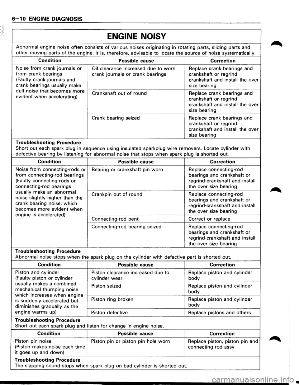
6-10 ENGINE DIAGNOSIS
ENGINE
NOISY
Abnormal engine noise often consists of various noises originating in rotating parts, sliding parts and
other moving parts
of the engine. It is, therefore, advisable to locate the source of noise systematically.
Condition
Possible cause Correction
Noise from crank journals or Oil clearance increased due to worn Replace crank bearings and
from crank bearings
crank journals
or crank bearings crankshaft or regrind
(Faulty crank journals and
crankshaft and
install the over
crank bearings
usually make
size bearing
dull noise that becomes more Crankshaft out of round
Replace crank bearings and
evident when accelerating)
crankshaft
or regrind
crankshaft and
install the over
size bearing
Crank bearing seized Replace crank bearings and
crankshaft or regrind
crankshaft and
install the over
size bearing
Troubleshooting Procedure
Short out each spark plug in sequence using insulated sparkplug wire removers. Locate cylinder with
defective bearing by listening for abnormal noise that stops when spark plug is shorted out.
Condition
Possible cause Correction
Noise from connecting-rods or Bearing or crankshaft pin worn Replace connecting-rod
from connecting-rod bearings
bearings and crankshaft or
(Faulty connecting-rods or regrind-crankshaft and install
connecting-rod bearings
the over size bearing
usually make an abnormal
Crankpin out of round Replace
connecting-rod
noise slightly higher than the
bearings and crankshaft
or crank bearing noise, which regrind-crankshaft and install becomes more evident when the over size bearing
engine is accelerated)
Connecting-rod bent
Correct or replace
Connecting-rod bearing seized Replace
connecting-rod
bearings and crankshaft
or
regrind-crankshaft and install
the over size bearing
Troubleshooting Procedure
Abnormal noise stops when the spark plug on the cylinder with defective part is shorted out.
Condition
Possible cause Correction
Piston and cylinder Piston clearance increased due to Replace piston and cylinder
(Faulty piston or cylinder
cylinder
wear body
usually makes a combined Piston seized Replace piston and cylinder
mechanical thumping noise body which increases when engine Piston ring broken Replace piston and cylinder
is suddenly accelerated but
diminishes gradually as the body
engine warms up) Piston defective Replace pistons and others
Troubleshooting Procedure
Short out each spark plug and listen for change in engine noise.
Condition
Possible cause Correction
Piston pin noise Piston pin or piston pin hole worn Replace piston, piston pin and
(Piston makes noise each time connecting-rod assy
it goes up and down)
Troubleshooting Procedure
The slapping sound stops when spark plug on bad cylinder is shorted out.
•
Page 511 of 1928
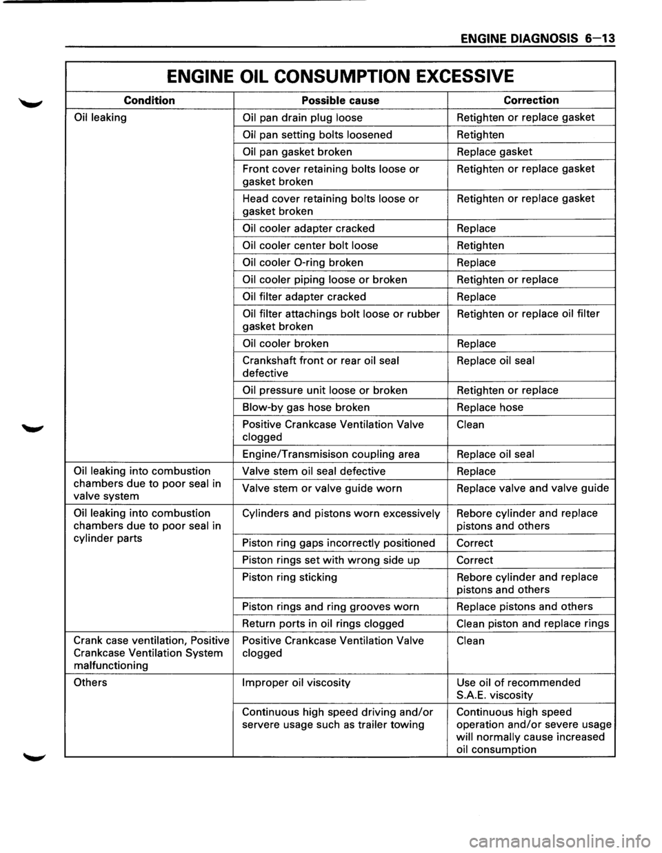
ENGINE DIAGNOSIS 6-13
ENGINE OIL CONSUMPTION EXCESSIVE
Condition Possible cause Correction
Oil leaking
Oil pan drain plug loose Retighten or replace gasket
Oil pan setting bolts loosened Retighten
Oil pan gasket broken Replace gasket
Front cover retaining
bolts loose or Retighten or replace gasket
gasket broken
Head cover retaining
bolts loose or Retighten or replace gasket
gasket broken
Oil cooler adapter cracked Replace
Oil cooler
center bolt loose Retighten
Oil cooler 0-ring broken Replace
Oil cooler
piping loose or broken Retighten or replace
Oil filter
adapter cracked Replace
Oil filter
attachings bolt loose or rubber Retighten or replace oil filter
gasket broken
Oil cooler broken Replace
Crankshaft front or rear oil seal Replace oil seal
defective
Oil pressure unit loose or broken Retighten or replace
Blow-by
gas hose broken Replace hose
Positive Crankcase Ventilation
Valve
Clean
clogged
Engine/Transmisison coupling area Replace oil seal
Oil leaking
into combustion Valve stem oil seal defective Replace
chambers due to poor seal in Valve stem or valve guide worn Replace valve and valve guide valve system
Oil leaking into combustion
Cylinders and pistons worn excessively Rebore cylinder and replace
chambers
due to poor seal in pistons and others
cylinder parts
Piston ring gaps incorrectly positioned
Correct
Piston rings set
with wrong side up
Correct
Piston ring sticking Rebore
cylinder and replace
pistons and others
Piston rings and ring grooves
worn Replace pistons and others
Return ports in
oil rings clogged Clean piston
and replace rings
Crank case ventilation, Positive
Positive Crankcase Ventilation
Valve Clean
Crankcase Ventilation System clogged
malfunctioning
Others Improper oil viscosity
Use oil of recommended
S.A.E. viscosity
Continuous high speed driving
and/or Continuous high speed
servere usage such
as trailer towing operation and/or severe usage
will normally cause increased
oil consumption
Page 512 of 1928
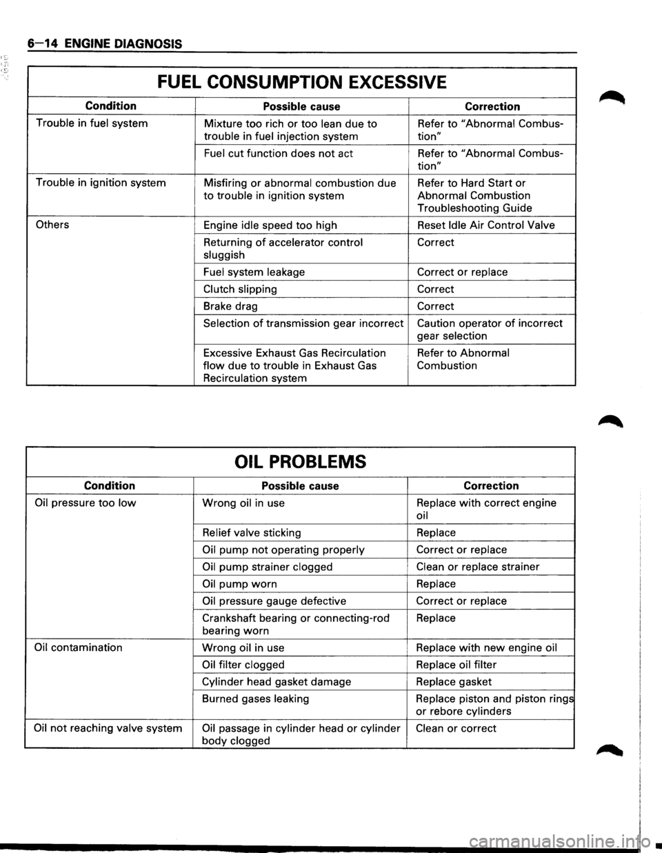
6-14 ENGINE DIAGNOSIS
1;:-
FUEL CONSUMPTION EXCESSIVE
Condition
Possible cause Correction
Trouble in fuel system
Mixture too rich or too lean due to Refer to "Abnormal Combus-
trouble in fuel injection system tion"
Fuel cut function does not act Refer to "Abnormal Combus-
tion"
Trouble in ignition system
Misfiring or abnormal combustion due Refer to Hard Start or
to trouble in ignition system Abnormal Combustion
Troubleshooting Guide
Others Engine idle speed too high Reset Idle Air Control Valve
Returning
of accelerator control Correct
sluggish
Fuel system leakage
Correct or replace
Clutch slipping Correct
Brake drag Correct
Selection of transmission gear incorrect Caution operator of incorrect
gear selection
Excessive Exhaust
Gas Recirculation Refer to Abnormal
flow due to trouble in Exhaust Gas Combustion
Recirculation system
OIL PROBLEMS
Condition
Possible cause Correction
Oil pressure too low Wrong oil in use Replace with correct
engine
oil
Relief valve sticking Replace
Oil pump not operating
properly Correct or replace
Oil pump strainer clogged Clean or replace strainer
Oil pump worn Replace
Oil pressure gauge defective Correct or replace
Crankshaft bearing or connecting-rod Replace
bearing
worn
Oil contamination Wrong oil in use Replace with new engine
oil
Oil filter clogged Replace oil filter
Cylinder head gasket damage Replace
gasket
Burned gases leaking Replace piston and piston rings
or rebore cylinders
Oil not reaching valve system Oil passage in cylinder head or cylinder Clean or correct
body clogged
•
Page 514 of 1928
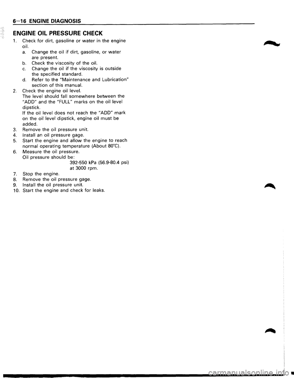
6-16 ENGINE DIAGNOSIS
ENGINE OIL PRESSURE CHECK
1. Check for dirt, gasoline or water in the engine
oil.
a. Change the oil if dirt, gasoline, or water
are present.
b. Check the viscosity of the oil.
c. Change the oil if the viscosity is outside
the specified standard.
d. Refer to the "Maintenance and Lubrication"
section of this manual.
2. Check the engine oil level.
The level should fall somewhere between the
"ADD" and the "FULL" marks on the oil level
dipstick.
If the oil level does not reach the "ADD" mark
on the
oil level dipstick, engine oil must be
added.
3. Remove the oil pressure unit.
4. Install an oil pressure gage.
5. Start the engine and allow the engine to reach
normal operating temperature (About 80°C).
6. Measure the oil pressure.
Oil pressure should be:
7. Stop the engine.
392-550 kPa (56.9-80.4 psi)
at
3000 rpm.
8. Remove the oil pressure gage.
9. Install the oil pressure unit.
10. Start the engine and check for leaks.
m ... cw
•
Page 515 of 1928
ENGINE DIAGNOSIS 6-17
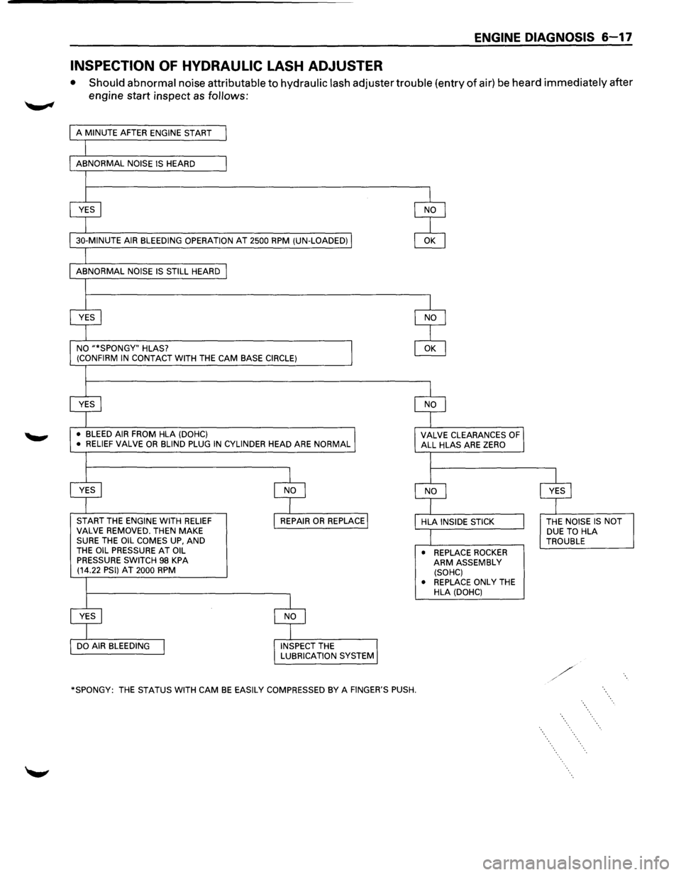
INSPECTION OF HYDRAULIC LASH ADJUSTER
• Should abnormal noise attributable to hydraulic lash adjuster trouble (entry of air) be heard immediately after
engine start inspect
as follows:
30-MINUTE AIR BLEEDING OPERATION AT 2500 RPM (UN-LOADED)
NO
"*SPONGY" HLAS?
(CONFIRM IN CONTACT WITH THE CAM BASE CIRCLE)
•
BLEED AIR FROM HLA (DOHC)
• RELIEF VALVE OR BLIND PLUG IN CYLINDER HEAD ARE NORMAL
START THE ENGINE WITH RELIEF VALVE REMOVED. THEN MAKE SURE THE OIL COMES UP, AND
THE OIL PRESSURE AT OIL
PRESSURE SWITCH 98 KPA (14.22 PSI) AT 2000 RPM
*SPONGY:
THE STATUS WITH CAM BE EASILY COMPRESSED BY A FINGER'S PUSH. •
REPLACE
ROCKER ARM ASSEMBLY
(SOHC)
• REPLACE
ONLY THE
HLA (DOHC) THE
NOISE IS NOT
DUE TO HLA
TROUBLE
Page 517 of 1928
GENERAL ENGINE MECHANICAL 6A-1
SECTION 6A
GENERAL ENGINE MECHANICAL
CONTENTS
Cylinder Head . . . . . . . . . . . . . . . . . . . . . . . . 6A-1
Valve Springs,
Oil Controller, Valve,
Valve Guide, (and HLA for
DOHC) . .
. . .
6A-4
Camshaft . .
. . . . . . . . . . . . . . . . . . . . . . . . . . GA-11
Rocker Arm Assembly . . . . . . . . . . . . . . . . .
GA-17
Oil Pump ............................ GA-20
Crankshaft ........................... GA-23
Piston and Connecting Rod ............. GA-30
Cylinder Block ........................ GA-37
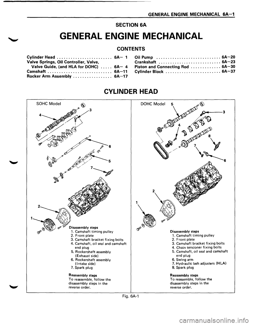
CYLINDER HEAD
SOHC Model
2
Disassembly steps
1. Camshaft timing pulley 2. Front plate
3. Camshaft bracket fixing bolts 4. Camshaft, oil seal and camshaft end plug
5. Rockershaft assembly (Exhaust side)
6. Rockershaft assembly (Intake side) 7. Spark plug
Reassembly steps
To reassemble, follow the disassembly steps in the reverse order.
DOHC Model
2
1
~
Fig. 6A-1
Disassembly steps
1. Camshaft timing pulley 2. Front plate 3. Camshaft bracket fixing bolts 4. Chain tensioner fixing bolts
5. Camshaft, oil seal and camshaft end plug
6. Swing arm 7. Hydraulic lash adjusters (HLA)
8.
Spark plug
Reassembly steps To reassemble, follow the disassembly steps in the reverse order.
Page 518 of 1928
6A-2 GENERAL ENGINE MECHANICAL
NOTE:
•
During disassembly, be sure that the valve train
components are kept
together and identified so
that they can be re-installed in their original
locations.
• Before removing the cylinder head from the
engine and before disassembling the valve
mechanism, perform a compression test and note
the results.
1•! .. 1 DISASSEMBLY
(SOHC)
1. Camshaft timing pulley
2. Front plate
3. Camshaft bracket fixing bolts
4. Camshaft, oil seal and camshaft end plug
• Remove them with camshaft bracket.
5. Rockershaft assembly (Exhaust side)
6. Rockershaft assembly (Intake side)
7. Spark plug
\fl CAUTION:
VI • Do not remove the spark plugs when the head
and plugs are hot.
• Clean dirt and debris from spark plug recess
areas.
(DOHC)
1. Camshaft timing pulley
2. Front plate
3. Camshaft bracket fixing bolts
4. Chain tensioner fixing bolts
5. Camshaft, oil seal and camshaft end plug
• Remove them with chain and chain tensioner
6. Swing arm.
7. Hydraulic lash adjusters (HLA)
NOTE:
Immerse HLA in engine oil, taking care nottoturn it
upside down or sideways in order to prevent any
air
from entering into HLA.
8. Spark plug
\flCAUTION:
VI • Do not remove the spark plugs when the head
and plugs are hot.
• Clean dirt and debris from spark plug recess
areas.
f}l CLEAN
• Cylinder head
Carefully remove
all varnish, soot and carbon
to the bare metal. Do not use a motorized wire
brush on any gasket sealing surface.
IL'~'IINSPECTION AND REPAIR
• Cylinder head gasket and mating surfaces for
leaks, corrosion and blow-by. If the gasket has
failed, determine the cause. Insufficient
torque on head bolts
Improper installation
Loose
or warped cylinder head
Missing
dowel pins
- Warped case surface
1. Cylinder head bolts for damaged threads or
stretching and damaged heads caused by
improper use of tools.
\fl CAUTION:
VI Replace used cylinder head bolts.
2. Cylinder head for cracks, especially between valve
seats and in the exhaust ports.
3. Cylinder head deck for corrosion, sand particles in
head and porosity.
\fl CAUTION:
VI Do not attemptto weld the cylinder head. Replace
it.
4. Cylinder head deck, intake and exhaust manifold
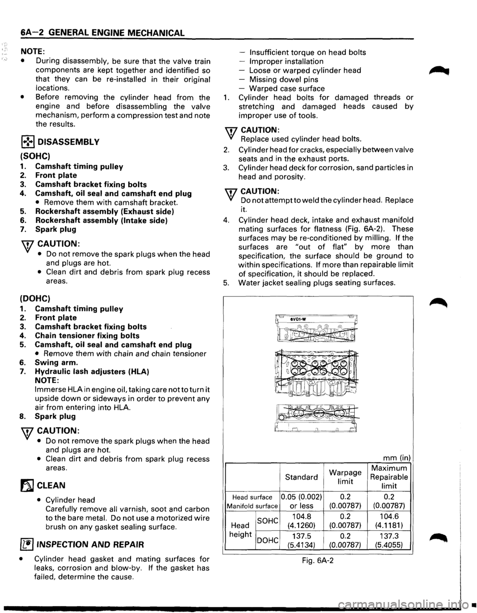
mating surfaces for flatness (Fig. 6A-2). These
surfaces
may be re-conditioned by milling. If the
surfaces are
"out of flat" by more than
specification, the surface should be ground
to
within specifications. If more than repairable limit
of specification, it should be replaced.
5. Water jacket sealing plugs seating surfaces.
IIVD1-w 8~
~ I 0 I ' 0 0 I 0
mm (in)
Warpage
Maximum
Standard Repairable limit limit
Head surface 0.05 (0.002) 0.2
0.2
Manifold surface or less (0.00787) (0.00787)
SOHC 104.8 0.2
104.6
Head (4.1260) (0.00787) (4.1181)
height
DOHC 137.5 0.2 137.3
(5.4134)
(0.00787) (5.4055)
Fig. 6A-2
•
Page 519 of 1928
1•!.,1 REASSEMBL V
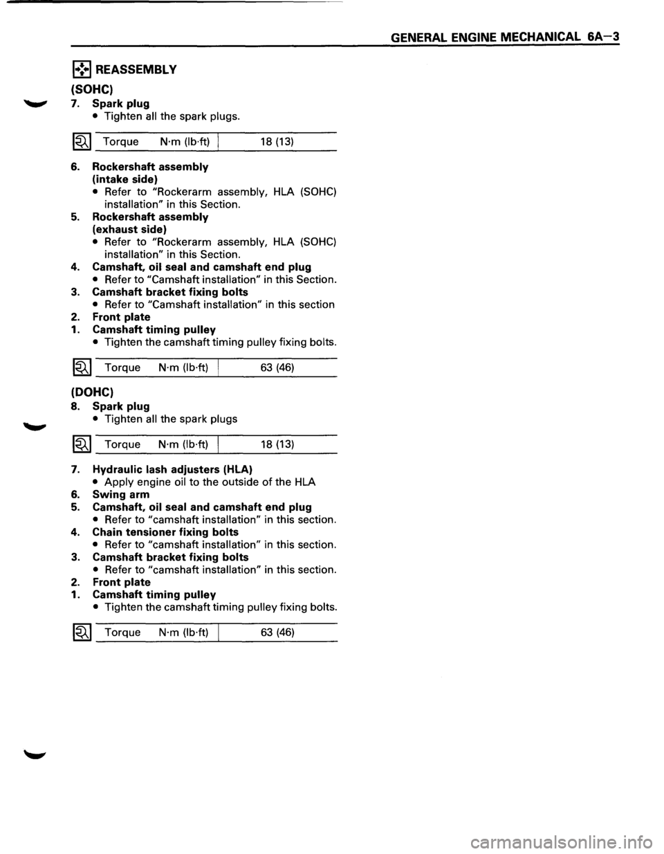
{SOHC)
~ 7. Spark plug
• Tighten all the spark plugs.
1~1 Torque N·m (lb·ft)
6. Rockershaft assembly
(intake side)
18 (13)
• Refer to "Rockerarm assembly, HLA (SOHC)
installation" in this Section.
5. Rockershaft assembly
(exhaust side)
• Refer to "Rockerarm assembly, HLA (SOHC)
installation" in this Section.
4. Camshaft, oil seal and camshaft end plug
• Refer to "Camshaft installation" in this Section.
3.
Camshaft bracket fixing bolts
• Refer to "Camshaft installation" in this section
2. Front plate
1. Camshaft timing pulley
• Tighten the camshaft timing pulley fixing bolts.
~~~ Torque N·m (lb·ft) 63 (46)
(DOHC)
8. Spark plug
• Tighten all the spark plugs
~~~ Torque N·m (lb·ft) I 18 (13)
7. Hydraulic lash adjusters (HLA)
• Apply engine oil to the outside of the HLA
6. Swing arm
5. Camshaft, oil seal and camshaft end plug
• Refer to "camshaft installation" in this section.
4. Chain tensioner fixing bolts
• Refer to "camshaft installation" in this section.
3. Camshaft bracket fixing bolts
• Refer to "camshaft installation" in this section.
2. Front plate
1. Camshaft timing pulley
• Tighten the camshaft timing pulley fixing bolts.
1~1 Torque N·m (lb·ft) 63 (46)
GENERAL ENGINE MECHANICAL 6A-3
Page 520 of 1928
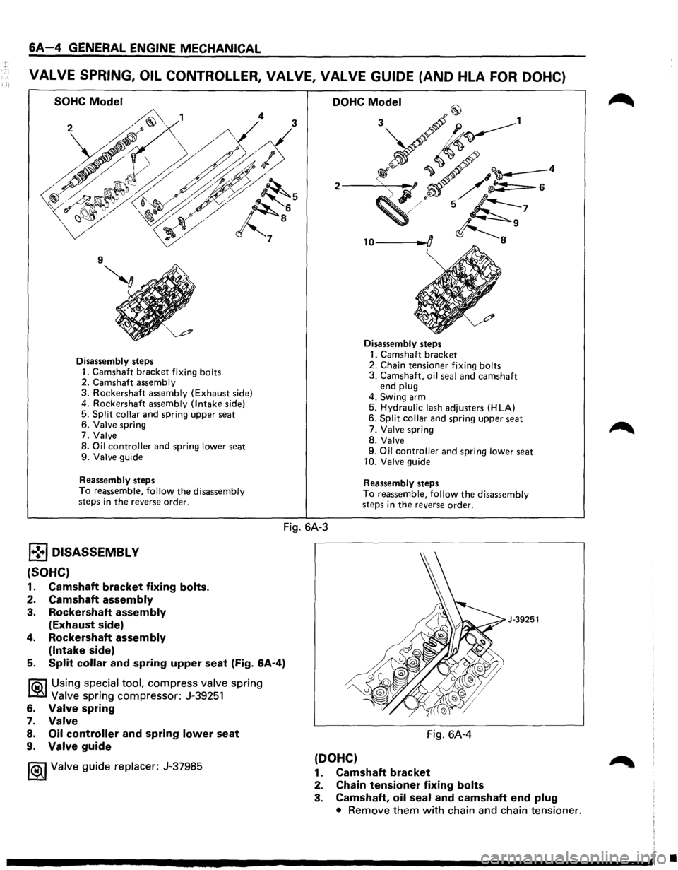
6A-4 GENERAL ENGINE MECHANICAL
VALVE SPRING, OIL CONTROLLER, VALVE, VALVE GUIDE (AND HLA FOR DOHC)
SOHC Model
Disassembly steps
1. Camshaft bracket fixing bolts 2. Camshaft assembly 3. Rockershaft assembly (Exhaust side)
4. Rockershaft assembly (Intake side)
5. Split collar and spring upper seat
6. Valve spring
7. Valve 8. Oil controller and spring lower seat 9. Valve guide
Reassembly
steps
To reassemble, follow the disassembly steps in the reverse order.
DOHC Model
, o-----~-~o
~'
Disassembly steps
1. Camshaft bracket 2. Chain tensioner fixing bolts 3. Camshaft, oil seal and camshaft end plug 4. Swing arm
5. Hydraulic lash adjusters (HLA)
6. Split collar and spring upper seat
7. Valve spring
8. Valve
9. Oil controller and spring lower seat 10. Valve guide
Reassembly
steps
To reassemble, follow the disassembly
steps in the reverse order.
Fig. 6A-3
j.! .. l DISASSEMBLY
(SOHC}
1. Camshaft bracket fixing bolts.
2. Camshaft assembly
3. Rockershaft assembly
(Exhaust side)
4. Rockershaft assembly
(Intake
side)
5. Split collar and spring upper seat (Fig. 6A-4)
li0\1 Using special tool, compress valve spring
~Valve spring compressor: J-39251
6. Valve spring
7. Valve
8. Oil controller and spring lower seat
9. Valve guide
1®.1 Valve guide replacer: J-37985
J-39251
Fig. 6A-4
(DOHC)
1. Camshaft bracket
2. Chain tensioner fixing bolts
3. Camshaft, oil seal and camshaft end plug
• Remove them with chain and chain tensioner.
•
Page 521 of 1928
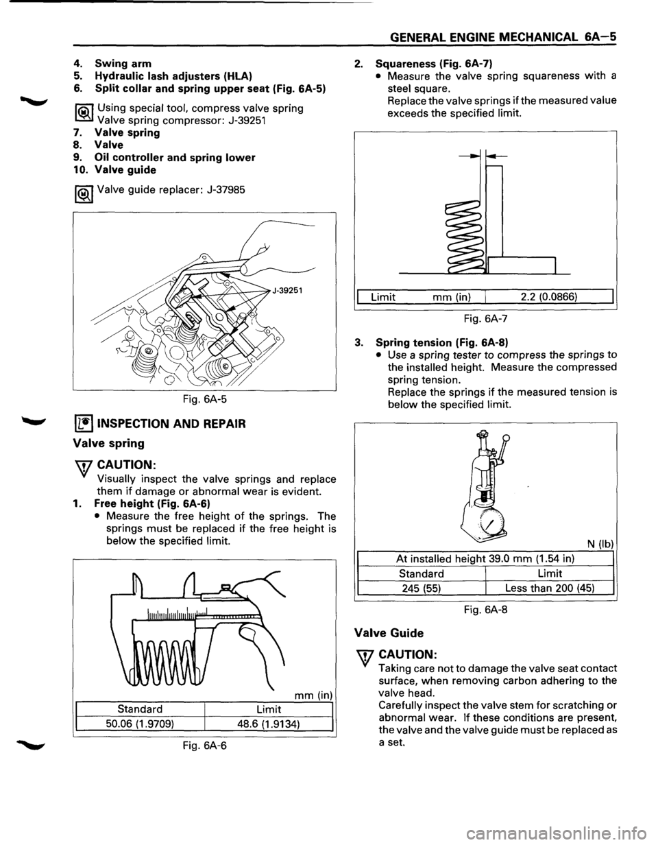
4. Swing arm
5. Hydraulic lash adjusters (HLA)
6. Split collar and spring upper seat (Fig. 6A-5)
l'iS\1 Using special tool, compress valve spring
~ Valve spring compressor: J-39251
7. Valve spring
8.
Valve
9. Oil controller and spring lower
10. Valve guide
1®..1 Valve guide replacer: J-37985
Fig. 6A-5
IL•IINSPECTION AND REPAIR
Valve spring
\fCAUTION:
Visually inspect the valve springs and replace
them
if damage or abnormal wear is evident.
1. Free height (Fig. 6A-6)
• Measure the free height of the springs. The
springs
must be replaced if the free height is
below the specified limit.
mm (in)
Standard Limit
50.06 (1.9709)
48.6 (1.9134)
Fig. 6A-6
GENERAL ENGINE MECHANICAL 6A-5
2. Squareness (Fig. 6A-7)
• Measure the valve spring squareness with a
steel square.
Replace the
valve springs if the measured value
exceeds the specified limit.
Limit mm (in) 2.2 (0.0866)
Fig. 6A-7
3. Spring tension (Fig. 6A-8)
• Use a spring tester to compress the springs to
the installed height. Measure the compressed
spring tension.
Replace the springs
if the measured tension is
below the specified limit.
N
(lb)
At installed height 39.0 mm (1.54 in)
Standard Limit
245
(55) Less than 200 (45)
Fig. 6A-8
Valve Guide
\fCAUTION:
Taking care not to damage the valve seat contact
surface, when removing carbon adhering to the
valve head.
Carefully inspect the valve stem for scratching or
abnormal wear.
If these conditions are present,
the
valve and the valve guide must be replaced as
a set.