sensor ISUZU TROOPER 1995 Workshop Manual
[x] Cancel search | Manufacturer: ISUZU, Model Year: 1995, Model line: TROOPER, Model: ISUZU TROOPER 1995Pages: 1928
Page 772 of 1928
6E2-76 DRIVEABILITY AND EMISSIONS
DIAGNOSTIC TROUBLE CODE (DTC) 33A
MANIFOLD ABSOLUTE PRESSURE (MAP) SENSOR CIRCUIT
(SIGNAL
VOLTAGE HIGH-LOW VACUUM)
Circuit Description:
The Manifold Absolute Pressure {MAP) Sensor responds to changes in manifold pressure (vacuum). The Engine
Control Module (ECM) receives this information as a signal voltage that will vary from about 1 to 1.5 volts, at closed
throttle idle, to 4-4.5 volts at
wide open throttle (low vacuum).
If the MAP sensor fails, the ECM will substitute a fixed MAP value based on Throttle Position Sensor to control fuel
delivery.
Test Description:
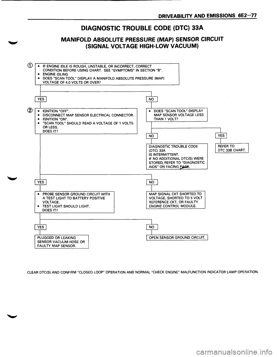
Numbers below refer to circled numbers on the diagnostic chart.
CD This step will determine if Diagnostic Trouble Code (DTC) 33 is the result of a hard failure or an intermittent
condition.
A
DTC 33 will set if:
• MAP signal indicates greater than 95 kPa (low vacuum).
• Throttle position sensor less than 2%.
• No DTC 21 A or DTC 21 B is set.
• These conditions are present for a time longer than 5.3 seconds.
® This step simulates conditions for a DTC 338. If the ECM recognizes the change, the ECM, and BLU/ORG and
GRY /RED wires are OK. If GRY wire is open, there may also be a DTC 23 stored.
Diagnostic Aids:
With the Ignition "ON" and the engine stopped, the manifold pressure is equal to atmospheric pressure and the
signal voltage
will be high. This information is used by the ECM as an indication of vehicle altitude and is referred ~
to as barometric pressure. Comparison of this barometric pressure reading with a known good vehicle with the
same sensor is a good
way to check accuracy of a "suspect" sensor. Readings should be the same ±0.4 volt.
A
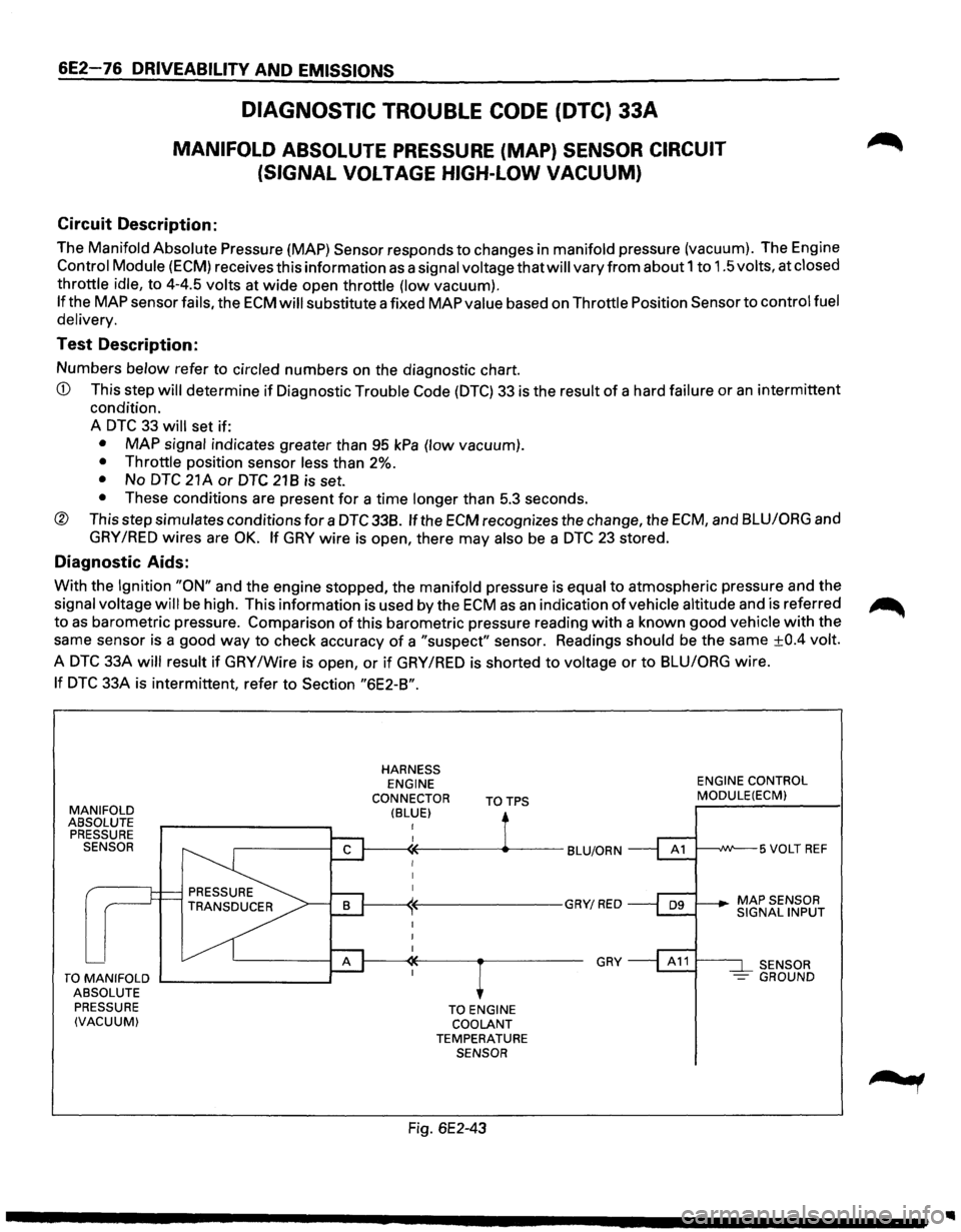
DTC 33A will result if GRY /Wire is open, or if GRY /RED is shorted to voltage or to BLU/ORG wire.
If DTC 33A is intermittent, refer to Section "6E2-B".
MANIFOLD ABSOLUTE
PRESSURE
SENSOR
TO MANIFOLD ....__ _______ __,
ABSOLUTE
PRESSURE
(VACUUM)
HARNESS ENGINE
CONNECTOR
(BLUE) TOTPS
TO ENGINE
COOLANT
TEMPERATURE SENSOR
Fig. 6E2-43
GRY
ENGINE CONTROL MODULE(ECM)
t---~W--5 VOLT REF
SENSOR
- GROUND
Page 773 of 1928
CD
®
DRIVEABILITY AND EMISSIONS 6E2-77
DIAGNOSTIC TROUBLE CODE (DTC) 33A
MANIFOLD ABSOLUTE PRESSURE (MAP) SENSOR CIRCUIT
(SIGNAL
VOLTAGE HIGH-LOW VACUUM)
• IF ENGINE IDLE IS ROUGH, UNSTABLE, OR INCORRECT, CORRECT CONDITION BEFORE USING CHART. SEE "SYMPTOMS" IN SECTION "B". • ENGINE IDLING
• DOES "SCAN TOOL" DISPLAY A MANIFOLD ABSOLUTE PRESSURE (MAP)
VOLTAGE OF 4.0 VOLTS OR OVER?
~ $
• IGNITION "OFF". •
DOES "SCAN TOOL" DISPLAY
• DISCONNECT MAP SENSOR ELECTRICAL CONNECTOR. MAP SENSOR VOLTAGE LESS
• IGNITION "ON". THAN 1 VOLT? • "SCAN TOOL" SHOULD READ A VOLTAGE OF 1 VOLTS I OR LESS.
DOES IT?
$ $
DIAGNOSTIC TROUBLE
CODE l REFER TO J (DTC) 33A DTC
33B CHART. IS INTERMITTENT. IF NO ADDITIONAL DTC(S) WERE STORED, REFER TO "DIAGNOSTIC AIDS" ON FACING ~-
~ $
• PROBE SENSOR GROUND CIRCUIT WITH MAP SIGNAL CKT SHORTED TO A TEST LIGHT TO BATTERY POSITIVE VOLTAGE,
SHORTED TO 5 VOLT
VOLTAGE. REFERENCE CKT, OR FAULTY • TEST LIGHT SHOULD LIGHT. ENGINE CONTROL MODULE.
DOES IT?
$ $
PLUGGED OR LEAKING OPEN SENSOR GROUND CIRCUIT.
SENSOR VACUUM HOSE OR FAULTY MAP SENSOR.
CLEAR DTC(S) AND CONFIRM "CLOSED LOOP" OPERATION AND NORMAL "CHECK ENGINE" MALFUNCTION INDICATOR LAMP OPERATION.
Page 774 of 1928
6E2-78 DRIVEABILITV AND EMISSIONS
DIAGNOSTIC TROUBLE CODE (DTC) 338
MANIFOLD ABSOLUTE PRESSURE (MAP) SENSOR CIRCUIT
(SIGNAL
VOLTAGE LOW-HIGH VACUUM)
Circuit Description:
The Manifold Absolute Pressure (MAP) Sensor responds to changes in manifold pressure (vacuum). The Engine
Control Module (ECM) receives this information as a signal voltage that will vary from about 0.45 to 0.85 volts, at
closed throttle idle, to 3.8-4.5 volts at Wide Open Throttle (low vacuum).
If the MAP sensor fails, the ECM will substitute a fixed MAP value based on Throttle Position Sensor to control fuel
delivery.
Test Description:
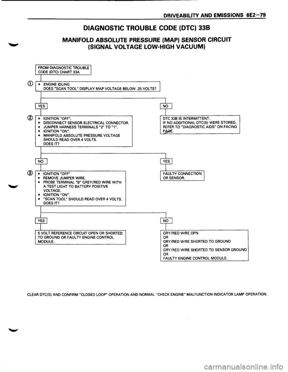
Numbers below refer to circled numbers on the diagnostic chart.
CD This step will determine if Diagnostic Trouble Code (DTC) 338 is the result of a hard failure or an intermittent
condition.
A
DTC 338 will set if:
• Engine speed is greater than 1100 revolution per minute.
• Throttle position sensor is greater than 20%.
•
MAP signal indicates less then 10.7 kPa.
• These conditions are present for a time longer than 0.125 seconds.
• No DTC 21 A or DTC 21 8 is set.
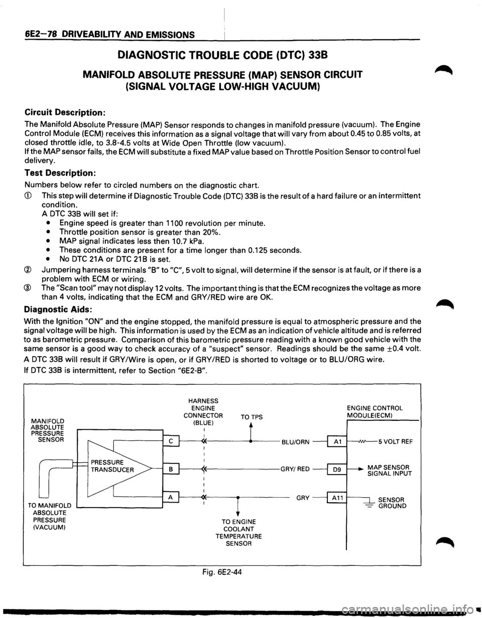
® Jumpering harness terminals "8" to "C", 5 volt to signal, will determine if the sensor is at fault, or if there is a
problem with ECM or wiring.
® The "Scan tool" may not display 12 volts. The important thing is that the ECM recognizes the voltage as more
than 4
volts, indicating that the ECM and GAY /RED wire are OK.
Diagnostic Aids:
With the Ignition "ON" and the engine stopped, the manifold pressure is equal to atmospheric pressure and the
signal voltage will be high. This information is used by the ECM as an indication of vehicle altitude and is referred
to as barometric pressure. Comparison of this barometric pressure reading with a known good vehicle with the
same sensor is a good
way to check accuracy of a "suspect" sensor. Readings should be the same ±0.4 volt.
A DTC 338 will result if GAY /Wire is open, or if GAY /RED is shorted to voltage or to 8LUIORG wire.
If DTC 338 is intermittent, refer to Section "6E2-8".
MANIFOLD ABSOLUTE
PRESSURE SENSOR
TO MANIFOLD .._ _______ --.~
ABSOLUTE
PRESSURE
(VACUUM)
HARNESS ENGINE
CONNECTOR
(BLUE) TOTPS
TO ENGINE COOLANT TEMPERATURE SENSOR
Fig. 6E2-44
GRY
ENGINE CONTROL MODULE(ECM)
SENSOR -GROUND
..
Page 775 of 1928
DRIVEABILITY AND EMISSIONS 6E2-79
DIAGNOSTIC TROUBLE CODE (DTC) 338
MANIFOLD ABSOLUTE PRESSURE (MAP) SENSOR CIRCUIT
(SIGNAL VOLTAGE LOW-HIGH
VACUUM)
CD • ENGINE IDLING
DOES "SCAN TOOL" DISPLAY MAP VOLTAGE BELOW .25 VOLTS?
@ • IGNITION "OFF".
• DISCONNECT SENSOR ELECTRICAL CONNECTOR.
•
JUMPER HARNESS TERMINALS "2" TO "1". • IGNITION "ON". • MANIFOLD ABSOLUTE PRESSURE VOLTAGE SHOULD READ OVER 4 VOLTS.
DOES IT?
@ • IGNITION "OFF"
• REMOVE JUMPER WIRE.
• PROBE TERMINAL "B" GREY /RED WIRE WITH 'W' A TEST LIGHT TO BATTERY POSITIVE VOLTAGE. • IGNITION "ON". • "SCAN TOOL" SHOULD READ OVER 4 VOLTS.
DOES IT?
5 VOLT REFERENCE CIRCUIT OPEN OR SHORTED
TO GROUND OR FAUL TV ENGINE CONTROL MODULE.
DTC 33B IS INTERMITTENT. IF NO ADDITIONAL DTC{S) WERE STORED, REFER TO "DIAGNOSTIC AIDS" ON FACING p
GRY/RED WIRE OPN OR GRY/RED WIRE SHORTED TO GROUND OR GRY/RED WIRE SHORTED TO SENSOR GROUND OR FAUL TV ENGINE CONTROL MODULE.
CLEAR DTC{S) AND CONFIRM "CLOSED LOOP" OPERATION AND NORMAL "CHECK ENGINE" MALFUNCTION INDICATOR LAMP OPERATION.
Page 776 of 1928
6E2-80 DRIVEABILITV AND EMISSIONS
Circuit Description:
DIAGNOSTIC TROUBLE CODE (DTC) 42
IGNITION CONTROL (IC) CIRCUIT
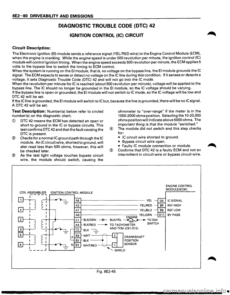
The Electronic Ignition (EI) module sends a reference signal (YEL/RED wire) to the Engine Control Module (ECM),
when the engine is cranking. While the engine speed is under 500 revolution per minute, the ignition control (IC)
module will control ignition timing. When the engine speed exceeds 500 revolution per minute, the ECM applies 5
volts to the bypass line to switch the timing to ECM control.
When the system is running on the El module, that is, no voltage on the bypass line, the El module grounds the IC
signal. The ECM expects to sense or detect no voltage on the IC line during this condition. If it senses or detects a
voltage,
it sets Diagnostic Trouble Code (DTC) 42 and will not go into the IC mode.
When the revolution per minute
for IC is reached (about 500 revolution per minute), voltage will be applied to the
bypass
line. The IC should no longer be grounded in the El module, so the IC voltage should be varying.
If the bypass line is open or grounded, the El module will not switch to IC mode, so the IC voltage will be low and
DTC 42 will be set.
If the IC line is grounded, the El module will switch to IC but, because the line is grounded, there will be no IC signal.
A DTC 42 will be set.
Test Description: Number(s) below refer to circled
number(s) on the diagnostic chart.
CD DTC 42 means the ECM has detected an open or
short to ground in the IC or bypass circuits. This
test confirms
DTC 42 and that the fault causing the
DTC is present.
® Checks for a normaiiC ground path through the IC
module. An IC circuit wire, shorted to ground, will
also
read less than 500 ohms, however, this will
be checked later.
® As the test light voltage touches bypass circuit
wire, the
module should switch, causing the ohmmeter
to "over-range" if the
meter is in the
1000-2000 ohms position. Selecting the 10-20,000
ohms position will indicate above 5000 ohms. The
important thing is that the module
"switched."
® The module did not switch and this step checks
for:
• IC circuit wire shorted to ground.
• Bypass circuit wire open.
• Faulty IC module connection or module.
@ Confirms that DTC 42 is a faulty ECM and not an
intermittent in circuit wire or bypass circuit wire.
ENGINE CONTROL
MODULE(ECM)
~--------------------------VEL
~----------------------YE~RED
~----------------------YE~BLU
IC SIGNAL
REF HIGH
REF LOW
BY PASS YE~GRN D11
BLK/ORN ----)}-BLK!YEL ~ TO IGN
BLK/RED -TO TACHOMETER SWITCH
BLK ~ AND TCM (C91-D12)
WHT :' '1 CRANKSHAFT
BLK -----..~ ! POSITION
WHT/RED ',_; 1 SENSOR
"SHIELD
Fig. 6E2-45
..
Page 778 of 1928
6E2-82 DRIVEABILITY AND EMISSIONS
Circuit Description:
DIAGNOSTIC TROUBLE CODE (DTC) 43
KNOCK SENSOR (KS) CIRCUIT
(DOHC)
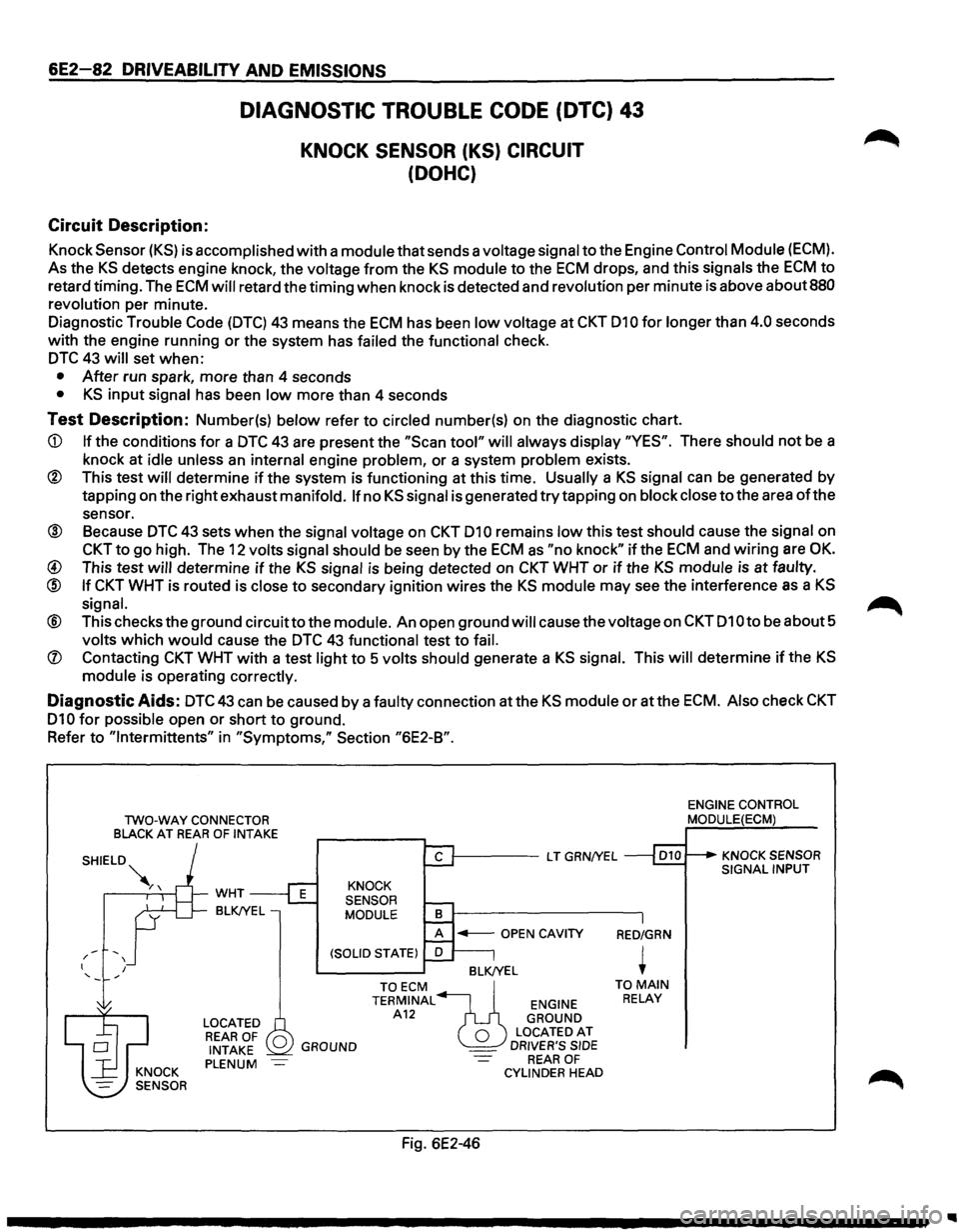
Knock Sensor (KS) is accomplished with a module that sends a voltage signal to the Engine Control Module (ECM).
As the KS detects engine knock, the voltage from the KS module to the ECM drops, and this signals the ECM to
retard timing. The ECM will retard the timing when knock is detected and revolution per minute is above about 880
revolution
per minute.
Diagnostic
Trouble Code (DTC) 43 means the ECM has been low voltage at CKT 010 for longer than 4.0 seconds
with the engine running or the system has
failed the functional check.
DTC 43 will set when:
• After run spark, more than 4 seconds
• KS input signal has been low more than 4 seconds
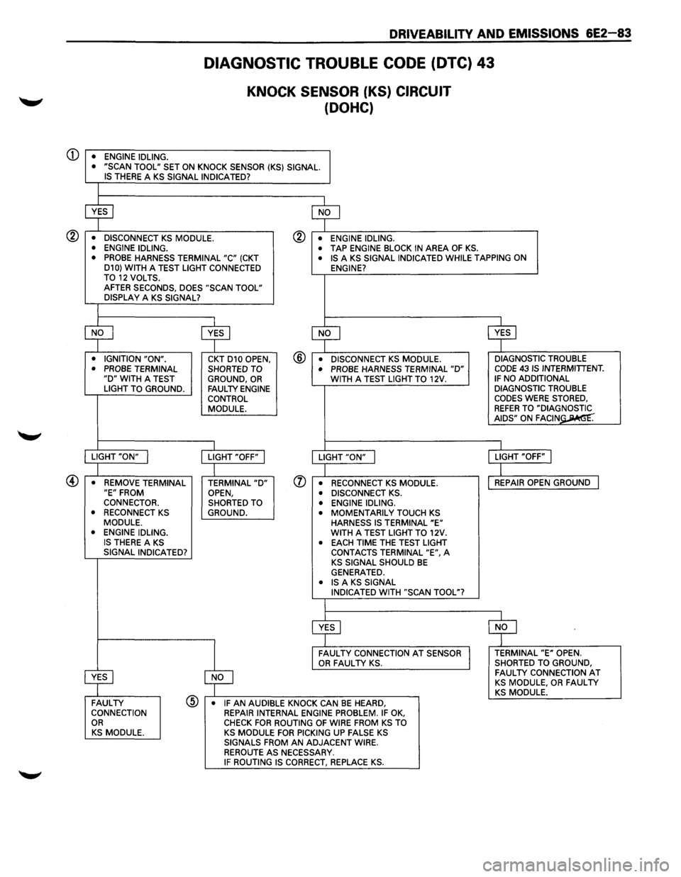
Test Description: Number(s) below refer to circled number(s) on the diagnostic chart.
CD If the conditions for a DTC 43 are present the "Scan tool" will always display "YES". There should not be a
knock at
idle unless an internal engine problem, or a system problem exists.
® This test will determine if the system is functioning at this time. Usually a KS signal can be generated by
tapping on the right exhaust
manifold. If no KS signal is generated try tapping on block close to the area of the
sensor.
® Because DTC 43 sets when the signal voltage on CKT 010 remains low this test should cause the signal on
CKT to go high. The 12 volts signal should be seen by the ECM as "no knock" if the ECM and wiring are OK.
@ This test will determine if the KS signal is being detected on CKT WHT or if the KS module is at faulty.
@ If CKT WHT is routed is close to secondary ignition wires the KS module may see the interference as a KS
signal. ~
® This checks the ground circuitto the module. An open ground will cause the voltage on CKT 010 to be about 5
volts which would cause the DTC 43 functional test to fail.
(J) Contacting CKT WHT with a test light to 5 volts should generate a KS signal. This will determine if the KS
module is operating correctly.
Diagnostic Aids: DTC43 can be caused by a faulty connection atthe KS module or atthe ECM. Also check CKT
010 for possible open or short to ground.
Refer
to "lntermittents" in "Symptoms," Section "6E2-B".
TWO-WAY CONNECTOR
BLACK AT REAR OF INTAKE
-' / I I
WHT
BLK!YEL
LOCATED REAR OF 0 INTAKE PLENUM
1-----L T GRN/YEL
KNOCK
SENSOR
MODULE
BLK/YEL
GROUND
TOECM ~ TERMINAL ENGINE A12 GROUND
0 LOCATEDAT _ DRIVER'S SIDE REAR OF CYLINDER HEAD
Fig. 6E2-46
RED/GRN
+ TO MAIN RELAY
ENGINE CONTROL MODULE(ECM)
KNOCK SENSOR SIGNAL INPUT
Page 779 of 1928
CD
DRIVEABILITV AND EMISSIONS 6E2-83
• ENGINE IDLING.
DIAGNOSTIC TROUBLE CODE (DTC) 43
KNOCK SENSOR (KS) CIRCUIT
(DOHC)
• "SCAN TOOL" SET ON KNOCK SENSOR (KS} SIGNAL. IS THERE A KS SIGNAL INDICATED?
~ $
• DISCONNECT KS MODULE. ® • ENGINE IDLING.
• ENGINE IDLING. • TAP ENGINE BLOCK IN AREA OF KS. • PROBE HARNESS TERMINAL "C" (CKT • IS A KS SIGNAL INDICATED WHILE TAPPING ON
D10} WITH A TEST LIGHT CONNECTED
ENGINE?
TO 12 VOLTS. AFTER SECONDS, DOES "SCAN TOOL"
DISPLAY A KS SIGNAL?
$ ~ ~ ~ • IGNITION "ON". CKT D10 OPEN, @ • DISCONNECT KS MODULE. DIAGNOSTIC
TROUBLE
• PROBE TERMINAL SHORTED TO • PROBE HARNESS TERMINAL "D" CODE 43 IS INTERMITTENT. "D" WITH A TEST
GROUND, OR WITH A TEST LIGHT TO 12V. IF NO ADDITIONAL
LIGHT TO GROUND. FAULTY ENGINE DIAGNOSTIC TROUBLE
CONTROL CODES WERE STORED,
MODULE.
REFER TO "DIA~= AIDS" ON FAGIN .
I I
LIGHT "ON" I LIGHT "OFF" I LIGHT "ON" j LIGHT "OFF" I
I
I
• REMOVE TERMINAL TERMINAL "D" (J) • RECONNECT KS MODULE. REPAIR
OPEN GROUND I "E" FROM
OPEN, • DISCONNECT KS . CONNECTOR.
SHORTED TO • ENGINE IDLING.
• RECONNECT KS GROUND. • MOMENTARILY TOUCH KS MODULE.
HARNESS IS TERMINAL "E" • ENGINE IDLING. WITH A TEST LIGHT TO 12V. IS THERE A KS • EACH TIME THE TEST LIGHT
SIGNAL INDICATED?
CONTACTS TERMINAL "E", A KS SIGNAL SHOULD BE GENERATED. • IS A KS SIGNAL
INDICATED WITH "SCAN TOOL"?
~ $
~
FAULTY CONNECTION AT SENSOR TERMINAL "E" OPEN. OR FAULTY KS. SHORTED
TO GROUND,
~
FAULTY CONNECTION AT KS MODULE, OR FAULTY KS MODULE. FAULTY @ • IF AN AUDIBLE KNOCK CAN BE HEARD, CONNECTION
REPAIR INTERNAL ENGINE PROBLEM. IF OK, OR CHECK FOR ROUTING OF WIRE FROM KS TO KS MODULE. KS MODULE FOR PICKING UP FALSE KS SIGNALS FROM AN ADJACENT WIRE.
REROUTE AS NECESSARY. IF ROUTING IS CORRECT, REPLACE KS.
Page 780 of 1928
6E2-84 DRIVEABILITY AND EMISSIONS
DIAGNOSTIC TROUBLE CODE (DTC) 44
HEATED OXYGEN SENSOR (H02S) CIRCUIT
(LEAN HEATED OXYGEN SENSOR (H02S) SIGNAL INDICATED)
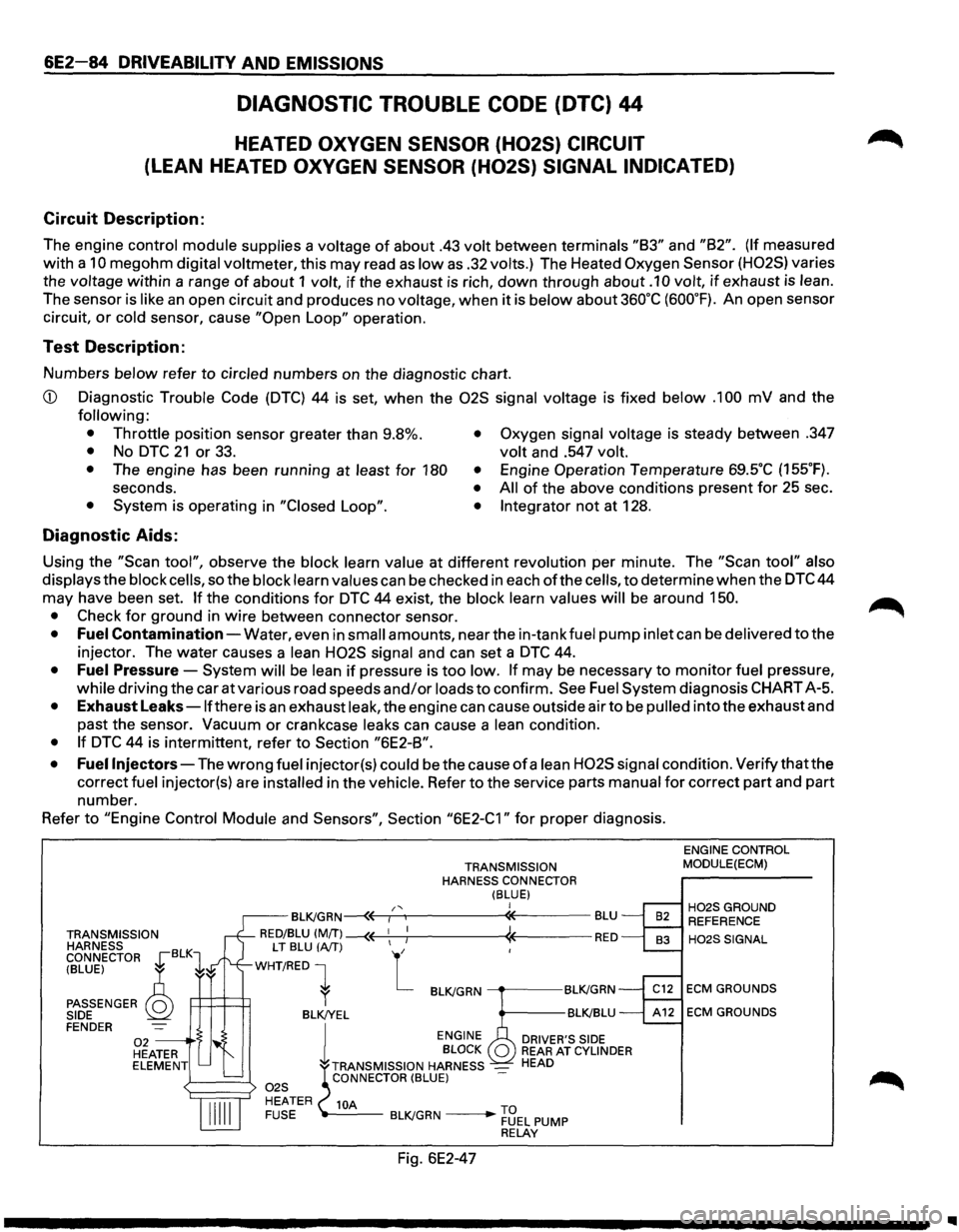
Circuit Description:
The engine control module supplies a voltage of about .43 volt between terminals "83" and "82". (If measured
with a
10 megohm digital voltmeter, this may read as low as .32 volts.) The Heated Oxygen Sensor (H02S) varies
the
voltage within a range of about 1 volt, if the exhaust is rich, down through about .1 0 volt, if exhaust is lean.
The sensor is like an open circuit and produces no voltage, when it is below about 360°C (600°F). An open sensor
circuit,
or cold sensor, cause "Open Loop" operation.
Test Description:
Numbers below refer to circled numbers on the diagnostic chart.
CD Diagnostic Trouble Code (DTC) 44 is set, when the 02S signal voltage is fixed below .1 00 mV and the
following:
• Throttle
position sensor greater than 9.8%.
• No DTC 21 or 33. • Oxygen signal voltage is steady between .347
volt and .547 volt.
•
The engine has been running at least for 180 •
seconds. • • System is operating in "Closed Loop". •
Engine Operation Temperature 69SC (155°F).
All of the above conditions present for 25 sec .
Integrator not at 128 .
Diagnostic Aids:
Using the "Scan tool", observe the block learn value at different revolution per minute. The "Scan tool" also
displays
the block cells, so the block learn values can be checked in each ofthe cells, to determine when the DTC 44
may have been set.
If the conditions for DTC 44 exist, the block learn values will be around 150.
•
Check for ground in wire between connector sensor.
• Fuel Contamination-Water, even in small amounts, near the in-tank fuel pump inlet can be delivered to the
injector. The water causes a
lean H02S signal and can set a DTC 44.
• Fuel Pressure-System will be lean if pressure is too low. If may be necessary to monitor fuel pressure,
while driving the car at various road speeds and/or loads to confirm. See Fuel System diagnosis CHART A-5.
• Exhaust Leaks -lfthere is an exhaust leak, the engine can cause outside air to be pulled into the exhaust and
past the sensor.
Vacuum or crankcase leaks can cause a lean condition.
• If DTC 44 is intermittent, refer to Section "6E2-8".
• Fuel
Injectors-The wrong fuel injector(s) could be the cause of a lean H02S signal condition. Verify that the
correct
fuel injector(s) are installed in the vehicle. Refer to the service parts manual for correct part and part
number.
Refer
to "Engine Control Module and Sensors", Section "6E2-C1" for proper diagnosis.
TRANSMISSION
HARNESS
CONNECTOR
~BLK1
TRANSMISSION
HARNESS CONNECTOR
(BLUE) I /' BL~GRN~r-~----------~-------BLU
RED/BLU (MfT) --(( 1
1 ; « RED
(BLUE) ~
PASSENGER Q SIDE
LT BLU (A/T) L
WHT/RED 1
P:::l=t=t1 l BL~GRN ----.-----BL~GRN
BLK!YEL BL~BLU FENDER 02 --·S HEATER ELEMENT l
ENGINE
DRIVER'S SIDE BLOCK REAR AT CYLINDER
TRANSMISSION HARNESS _ HEAD CONNECTOR (BLUE)
10A -----BL~GRN ____ .,.... ~3EL PUMP RELAY
Fig. 6E2-47
ENGINE CONTROL
MODULE(ECM)
H02SGROUND REFERENCE
H02SSIGNAL
ECM GROUNDS
ECM GROUNDS
..
Page 781 of 1928
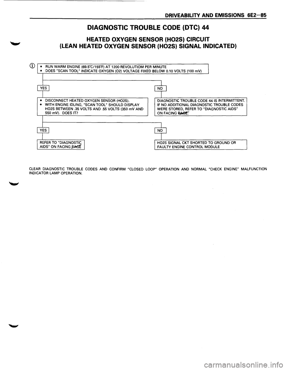
DRIVEABILITY AND EMISSIONS 6E2-85
DIAGNOSTIC TROUBLE CODE (DTC) 44
HEATED OXYGEN SENSOR (H02S) CIRCUIT
(LEAN HEATED OXYGEN SENSOR (H02S) SIGNAL INDICATED)
(j) •
RUN WARM ENGINE (69SC/155'F) AT 1200 REVOLUTIOM PER MINUTE
• DOES "SCAN TOOL" INDICATE OXYGEN (02) VOLTAGE FIXED BELOW 0.10 VOLTS (100 mV)
• DISCONNECT HEATED OXYGEN SENSOR (H02S).
• WITH ENGINE IDLING, "SCAN TOOL" SHOULD DISPLAY
H02S BETWEEN .35 VOLTS AND .55 VOLTS (350 mV AND 550 mV). DOES IT?
DIAGNOSTIC TROUBLE CODE 44 IS INTERMITTENT. IF NO ADDITIONAL DIAGNOSTIC TROUBLE CODES WERE STORED, REFER TO "DIAGNOSTIC AIDS" ON FACING I?,Aer.
H02S SIGNAL CKT SHORTED TO GROUND OR FAULTY ENGINE CONTROL MODULE
CLEAR DIAGNOSTIC TROUBLE CODES AND CONFIRM "CLOSED LOOP" OPERATION AND NORMAL "CHECK ENGINE" MALFUNCTION
INDICATOR LAMP OPERATION.
Page 782 of 1928
6E2-86 DRIVEABILITY AND EMISSIONS
DIAGNOSTIC TROUBLE CODE (DTC) 45
HEATED OXYGEN SENSOR (H02S) CIRCUIT
(RICH
HEATED OXYGEN SENSOR (H02S) SIGNAL INDICATED)
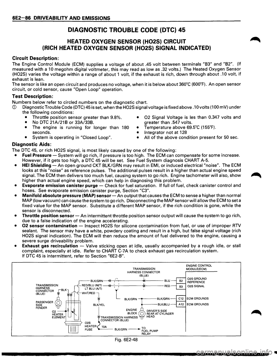
Circuit Description:
The Engine Control Module (ECM) supplies a voltage of about .45 volt between terminals "83" and "82". (If
measured with a 10 megohm digital voltmeter, this may read as low as .32 volts.) The Heated Oxygen Sensor
(H02S)
varies the voltage within a range of about 1 volt, if the exhaust is rich, down through about .1 0 volt, if
exhaust is lean.
The sensor is like an open circuit and produces no voltage, when it is below about 360"C (600"F). An open sensor
circuit,
or cold sensor, cause "Open Loop" operation.
Test Description:
Numbers below refer to circled numbers ·on the diagnostic chart.
CD Diagnostic Trouble Code (DTC) 45 is set, when the H02S signal voltage is fixed above .1 0 volts (1 00 mV) under
the
following conditions:
• Throttle position sensor greater than 9.8%. • 02 Signal Voltage is les than 0.347 volts and
• No DTC 21 A/21 8 or 33A/338. greater than .547 volts.
•
The engine is running for longer than 180 • Temperature above 69.5"C (155"F).
seconds. • Integrator not at 128
• System is operating in "Closed Loop". • All of the above condition present for 50 sec.
Diagnostic Aids:
The DTC 45, or rich H02S signal, is most likely caused by one of the following:
• Fuel Pressure-System will go rich, if pressure is too high. The ECM can compensate for some increase.
However,
if it gets too high, a DTC 45 will be set. See Fuel System diagnosis CHART A-5.
• HEI Shielding-An open ground CKT BLK/GRN may result in EMI, or induced electrical "noise". The ECM
looks at this "noise" as reference pulses. The additional pulses result in a higher than actual engine speed
signal. The ECM then delivers too much fuel, causing system to go rich. Engine tachometer will also, show ~
higher than actual engine speed, which can help in diagnosing this problem.
• Evaporate emission canister purge-Check for fuel saturation. If full of fuel, check canister control and
hoses.
See evaporate emission canister purge, Section "C3".
• Manifold absolute pressure (MAP) sensor-An output that causes the ECM to sense a higher than normal
MAP (low vacuum) can causethesystemto go rich. Disconnecting the MAP sensor will allow the ECMtoseta
fixed value for the MAP sensor. Substitute a different MAP sensor, if the rich condition is gone, while the
sensor is disconnected.
• Throttle position sensor-An intermittent throttle position sensor output will cause the system to go rich,
due
to a false indication of the engine accelerating.
• 02 sensor contamination -Inspect H02S for silicone contamination from fuel, or use of improper RTV
sealant. The sensor may have a white, powdery coating and result in a high, but false signal voltage (rich
H02S signal indication). The ECM will then reduce the amount of fuel delivered to the engine, causing a
severe surge driveability problem.
• Exhaust gas recirculation -Valve sticking open at idle, usually accompanied by a rough idle, or stall
complaint, especially at idle. Refer to CHART C-7A to check exhaust gas recirculation system.
If DTC 45 is intermittent, refer to Section "6E2-8".
TRANSMISSION
HARNESS
CONNECTOR ,[BLK1
TRANSMISSION
HARNESS CONNECTOR !BLUE I I ,, BLK!GRN~E----r:......,-----"*----BLU
RED/BLU (MfT) ~ 1
1 1 RED
(BLUE) ~
PASSENGER Q SIDE FENDER
L T
BLU (AfT) L WHT/RED 1
R=+=+=:R l BLK!GRN -----BLK!GRN
BLK/YEL BLK!BLU
1
ENGINE
BLOCK Q TRANSMISSION HARNESS -CONNECTOR (BLUE) -
DRIVER'S SIDE REAR AT CYLINDER HEAD
10A BLK/GRN -~~EL PUMP RELAY
Fig. 6E2-48
ENGINE CONTROL MODULE(ECM)
02SGROUND REFERENCE 02S SIGNAL
ECM GROUNDS
ECM GROUNDS
..