sensor ISUZU TROOPER 1995 Workshop Manual
[x] Cancel search | Manufacturer: ISUZU, Model Year: 1995, Model line: TROOPER, Model: ISUZU TROOPER 1995Pages: 1928
Page 743 of 1928
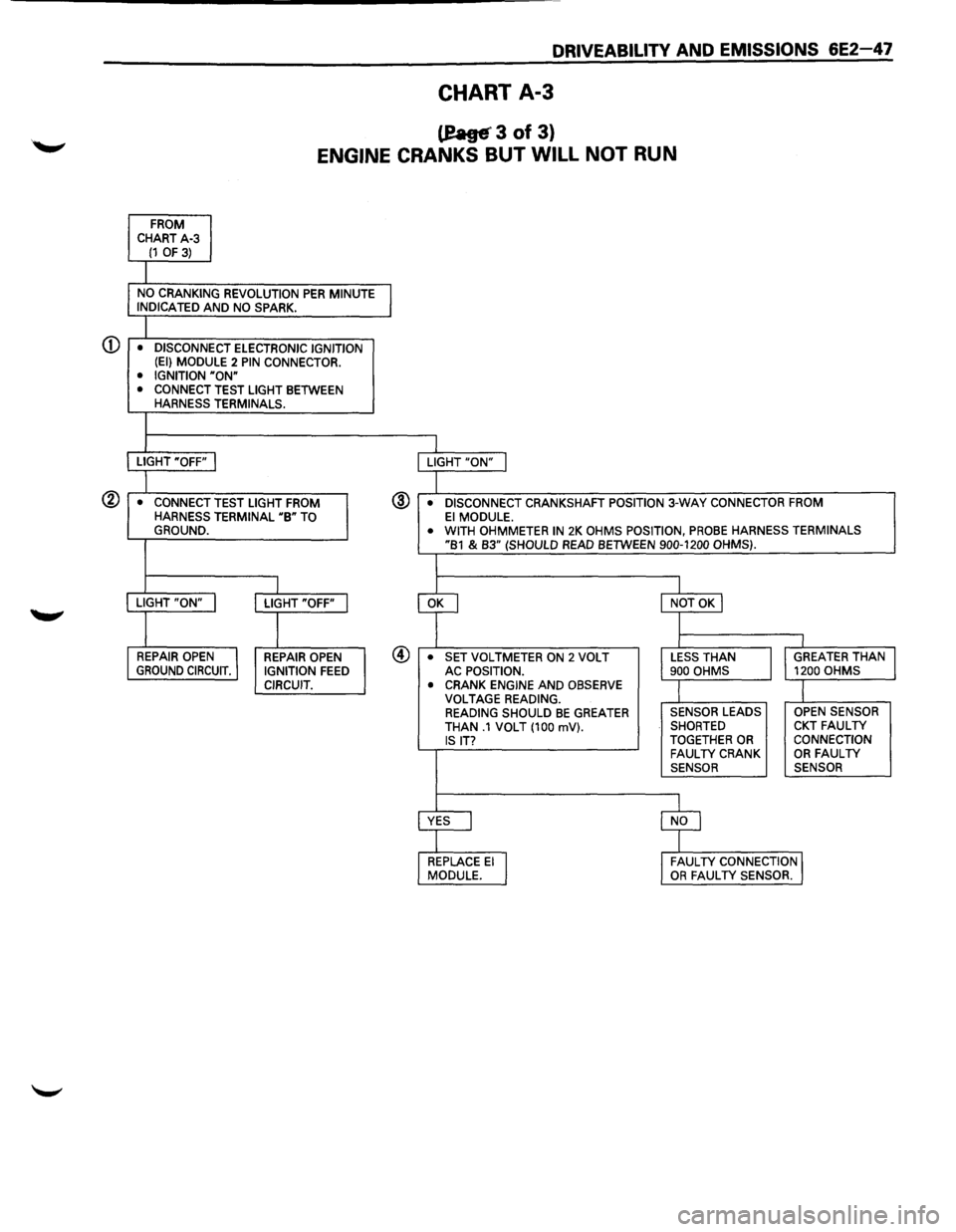
CHART A-3
teage' 3 of 3)
ENGINE CRANKS BUT WILL NOT RUN
FROM
CHART A-3 (1 OF 3)
NO CRANKING REVOLUTION PER MINUTE j INDICATED AND NO SPARK.
• DISCONNECT ELECTRONIC IGNITION
(EI) MODULE 2 PIN CONNECTOR.
• IGNITION "ON" • CONNECT TEST LIGHT BETWEEN HARNESS TERMINALS.
LIGHT "OFF"
I LIGHT "ON" I
• CONNECT TEST LIGHT FROM @ • DISCONNECT CRANKSHAFT POSITION 3-WAY CONNECTOR FROM
HARNESS TERMINAL "B" TO El MODULE.
GROUND. • WITH OHMMETER IN 2K OHMS POSITION, PROBE HARNESS TERMINALS "B1 & B3" (SHOULD READ BETWEEN 900-1200 OHMS).
I
cf
I LIGHT "ON" I LIGHT "OFF" I NOT OK I
I l I I
REPAIR OPEN
I REPAIR OPEN @ • SET VOLTMETER ON 2 VOLT LESS THAN
I
GREATER THAN GROUND CIRCUIT. IGNITION FEED AC POSITION. 900
OHMS 1200 OHMS CIRCUIT.
• CRANK ENGINE AND OBSERVE I l VOLTAGE READING. READING SHOULD BE GREATER SENSOR LEADS OPEN
SENSOR THAN .1 VOLT (100 mV). SHORTED CKT FAULTY IS IT? TOGETHER OR CONNECTION FAUL TV CRANK OR FAULTY SENSOR
SENSOR
YES
I
$
REPLACE El ~ MODULE. FAUL
TV CONNECTION J OR FAUL TV SENSOR.
Page 752 of 1928
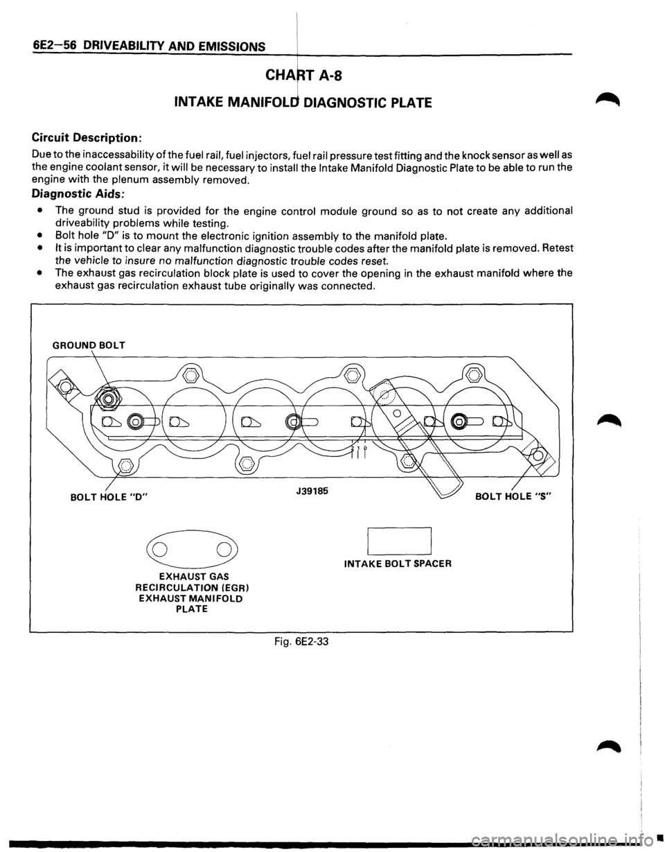
Circuit Description:
Due to the inaccessability of the fuel rail, fuel injectors, fuel rail pressure test fitting and the knock sensor as well as
the engine coolant sensor, it will be necessary to install the Intake Manifold Diagnostic Plate to be able to run the
engine with the
plenum assembly removed.
Diagnostic Aids:
• The ground stud is provided for the engine control module ground so as to not create any additional
driveability problems while
testing.
• Bolt hole "D" is to mount the electronic ignition assembly to the manifold plate.
• It
is important to clear any malfunction diagnostic trouble codes after the manifold plate is removed. Retest
the
vehicle to insure no malfunction diagnostic trouble codes reset.
• The exhaust gas recirculation block plate is used to cover the opening in the exhaust manifold where the
exhaust gas
recirculation exhaust tube originally was connected.
GROUND BOLT
~
EXHAUST GAS
RECIRCULATION
(EGR)
EXHAUST MANIFOLD PLATE
INTAKE BOLT SPACER
Fig. 6E2-33
•
Page 753 of 1928
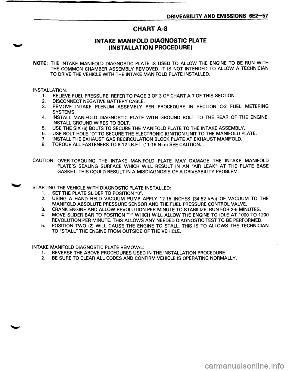
DRIVEABILITY AND EMISSIONS 6E2-57
CHART A-8
INTAKE MANIFOLD DIAGNOSTIC PLATE
(INSTALLATION PROCEDURE)
NOTE: THE INTAKE MANIFOLD DIAGNOSTIC PLATE IS USED TO ALLOW THE ENGINE TO BE RUN WITH
THE COMMON CHAMBER ASSEMBLY REMOVED. IT IS NOT INTENDED TO ALLOW A TECHNICIAN
TO
DRIVE THE VEHICLE WITH THE INTAKE MANIFOLD PLATE INSTALLED.
INSTALLATION:
1. RELIEVE FUEL PRESSURE. REFER TO PAGE 3 OF 3 OF CHART A-7 OF THIS SECTION.
2. DISCONNECT NEGATIVE BATTERY CABLE.
3. REMOVE INTAKE PLENUM ASSEMBLY PER PROCEDURE IN SECTION C-2 FUEL METERING
SYSTEMS.
4. INSTALL MANIFOLD DIAGNOSTIC PLATE WITH GROUND BOLT TO THE REAR OF THE ENGINE.
INSTALL
GROUND WIRES TO BOLT.
5. USE THE SIX (6) BOLTS TO SECURE THE MANIFOLD PLATE TO THE INTAKE ASSEMBLY.
6. USE BOLT HOLE "D" TO SECURE THE ELECTRONIC IGNITION UNIT TO THE MANIFOLD PLATE.
7. INSTALL THE EXHAUST GAS RECIRCULATION BLOCK PLATE AT EXHAUST MANIFOLD.
8. TORQUE ALL FASTENERS TO 8-12 LB.FT. (11-16 N·m) SEE CAUTION.
CAUTION: OVER-TORQUING
THE INTAKE MANIFOLD PLATE MAY DAMAGE THE INTAKE MANIFOLD
PLATE'S SEALING SURFACE WHICH WILL RESULT IN AN "AIR LEAK" AT THE PLATE BASE
GASKET. THIS COULD RESULT IN A MISDIAGNOSIS OF A DRIVEABILITY PROBLEM.
STARTING THE VEHICLE WITH DIAGNOSTIC PLATE INSTALLED:
1. SET THE PLATE SLIDER TO POSITION "0".
2. USING A HAND HELD VACUUM PUMP APPLY 12-15 INCHES (34-52 kPa) OF VACUUM TO THE
MANIFOLD ABSOLUTE PRESSURE SENSOR AND THE FUEL PRESSURE CONTROL VALVE.
3. CRANK ENGINE AND ALLOW REVOLUTION PER MINUTE TO STABILIZE. RUN FOR 2-5 MINUTES.
4. MOVE SLIDER BAR TO POSITION "1" WHICH WILL ALLOW THE ENGINE TO IDLE AT 1000 TO 1200
REVOLUTION
PER MINUTE. THIS ALLOWS ANY NEEDED DIAGNOSTIC TEST TO BE PERFORMED.
5. POSITION TWO (2) WILL CAUSE THE ENGINE TO STALL. THIS IS TO ALLOWS THE TECHNICIAN
TO "STALL"
THE ENGINE FROM OUTSIDE OF THE VEHICLE.
INTAKE MANIFOLD DIAGNOSTIC
PLATE REMOVAL:
1. REVERSE THE ABOVE PROCEDURES USED IN THE INSTALLATION PROCEDURE.
2. BE SURE TO CLEAR ALL CODES AND CONFIRM VEHICLE IS OPERATING NORMALLY.
Page 754 of 1928
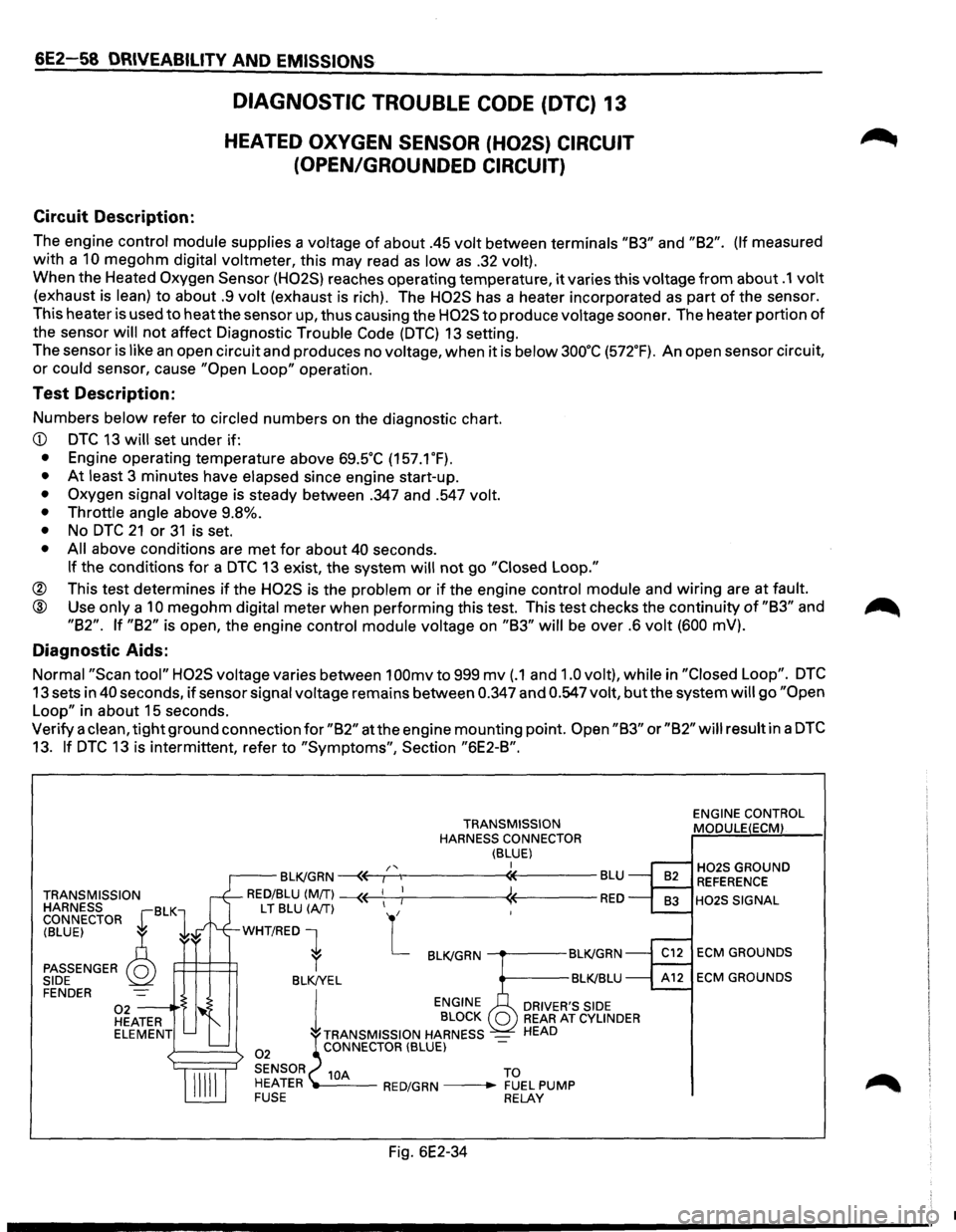
6E2-58 DRIVEABILITY AND EMISSIONS
Circuit Description:
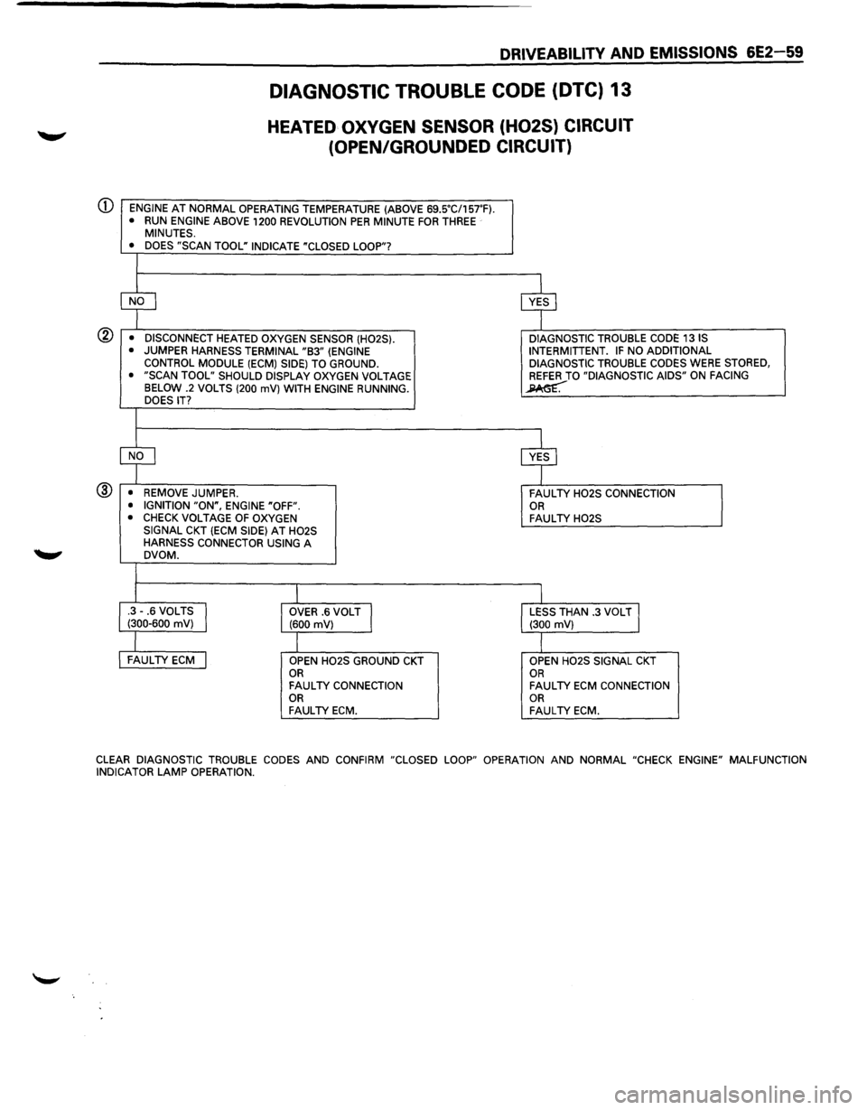
DIAGNOSTIC TROUBLE CODE (DTC) 13
HEATED OXYGEN SENSOR (H02S) CIRCUIT
(OPEN/GROUNDED CIRCUIT)
The engine control module supplies a voltage of about .45 volt between terminals "83" and "82". (If measured
with a
10 megohm digital voltmeter, this may read as low as .32 volt).
When the Heated Oxygen Sensor (H02S) reaches operating temperature, it varies this voltage from about .1 volt
(exhaust is lean) to about .9 volt (exhaust is rich). The H02S has a heater incorporated as part of the sensor.
This heater is used to
heatthe sensor up, thus causing the H02S to produce voltage sooner. The heater portion of
the sensor
will not affect Diagnostic Trouble Code (DTC) 13 setting.
The sensor
is like an open circuit and produces no voltage, when it is below 3oo·c (572.F). An open sensor circuit,
or could sensor, cause "Open Loop" operation.
Test Description:
Numbers below refer to circled numbers on the diagnostic chart.
• At least 3 minutes have elapsed since engine start-up.
• Oxygen signal voltage is steady between .347 and .547 volt.
• Throttle angle
above 9.8%.
• No DTC 21 or 31 is set.
• All above conditions are met for about 40 seconds.
If the conditions for a DTC 13 exist, the system will not go "Closed Loop."
® This test determines if the H02S is the problem or if the engine control module and wiring are at fault.
@ Use only a 10 megohm digital meter when performing this test. This test checks the continuity of "83" and
"82". If "82" is open, the engine control module voltage on "83" will be over .6 volt (600 mV).
Diagnostic Aids:
Normal "Scan tool" H02S voltage varies between 1 OOmv to 999 mv (.1 and 1.0 volt), while in "Closed Loop". DTC
13 sets in 40 seconds, if sensor signal voltage remains between 0.347 and 0.547 volt, but the system will go "Open
Loop"
in about 15 seconds.
Verify a
clean, tight ground connection for "82" at the engine mounting point. Open "83" or "82" will result in a DTC
13. If DTC 13 is intermittent, refer to "Symptoms", Section "6E2-8".
TRANSMISSION
HARNESS BLK CONNECTOR r 1
TRANSMISSION
HARNESS CONNECTOR
(BLUE) I /'< r--BLK/GRN ~~,---.,------«----BLU
RED/BLU (MIT) --« ! « RED
(BLUE) ~
PASSENGER Q SIDE
L T BLU (A/T) L
WHT/RED 1
P=H=~ r BLK/GRN ---.---BLK!GRN
BLK!YEL BLK!BLU FENDER
02 -----·'$ HEATER ELEMENT
02
l
ENGINE
BLOCK
TRANSMISSION HARNESS
-CONNECTOR (BLUE)
DRIVER'S SIDE REAR AT CYLINDER HEAD
SENSOR 10A TO
HEATER ---RED/GRN --• FUEL PUMP FUSE RELAY
Fig. 6E2-34
ENGINE CONTROL
MODULE(ECM)
H02S GROUND REFERENCE
H02S SIGNAL
ECM GROUNDS
ECM GROUNDS
•
Page 755 of 1928
Q)
®
DRIVEABILITV AND EMISSIONS 6E2-59
DIAGNOSTIC TROUBLE CODE {DTC) 13
HEATED OXYGEN SENSOR (H02S) CIRCUIT
(OPEN/GROUNDED CIRCUIT)
ENGINE AT NORMAL OPERATING TEMPERATURE (ABOVE 69SC/157'F). • RUN ENGINE ABOVE 1200 REVOLUTION PER MINUTE FOR THREE MINUTES.
• DOES "SCAN TOOL" INDICATE "CLOSED LOOP"?
~ cvf
• DISCONNECT HEATED OXYGEN SENSOR (H02S). DIAGNOSTIC
TROUBLE CODE 13 IS
• JUMPER HARNESS TERMINAL "B3" (ENGINE INTERMITIENT. IF NO
ADDITIONAL
CONTROL MODULE (ECM) SIDE) TO GROUND. DIAGNOSTIC TROUBLE CODES WERE STORED,
• "SCAN TOOL" SHOULD DISPLAY OXYGEN VOLTAGE REFER TO "DIAGNOSTIC AIDS" ON FACING
BELOW .2 VOLTS (200 mV) WITH ENGINE RUNNING. ~ DOES IT?
~ cvf
• REMOVE JUMPER.
FAULTY H02S CONNECTION
• IGNITION "ON", ENGINE "OFF". OR • CHECK VOLTAGE OF OXYGEN FAULTY H02S SIGNAL CKT (ECM SIDE) AT H02S HARNESS CONNECTOR USING A DVOM.
I I .3-.6 VOLTS I (300-600 mV) OVER .6 VOLT J (600 mV) LESS THAN .3 VOLT J (300 mV)
l I FAULTY ECM j OPEN H02S GROUND CKT OPEN H02S SIGNAL CKT OR OR FAULTY CONNECTION FAULTY ECM CONNECTION OR OR FAULTY ECM. FAULTY ECM.
CLEAR
DIAGNOSTIC TROUBLE CODES AND CONFIRM "CLOSED LOOP" OPERATION AND NORMAL "CHECK ENGINE" MALFUNCTION
INDICATOR LAMP OPERATION.
Page 756 of 1928
6E2-60 DRIVEABILITY AND EMISSIONS
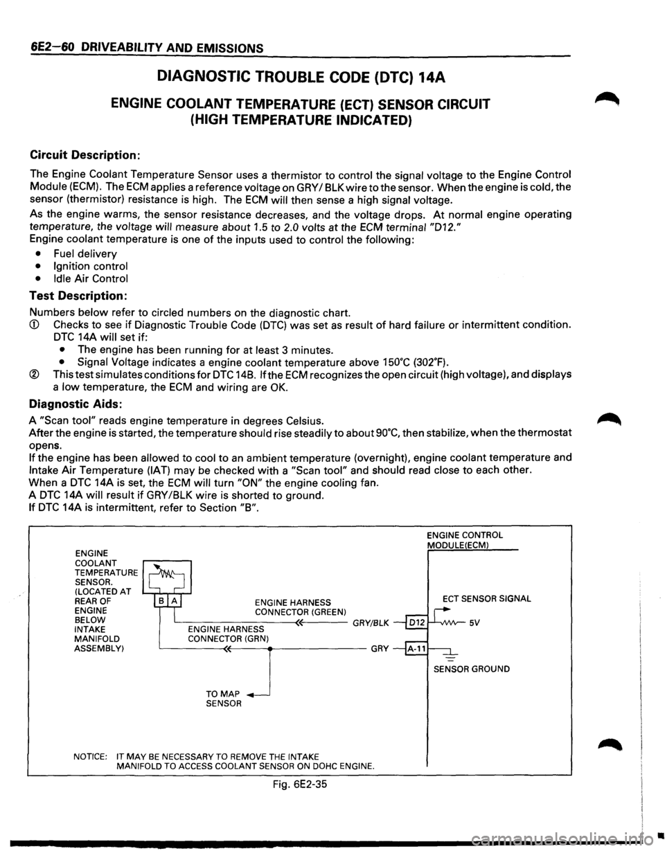
DIAGNOSTIC TROUBLE CODE (DTC) 14A
ENGINE COOLANT TEMPERATURE (ECT) SENSOR CIRCUIT
(HIGH
TEMPERATURE INDICATED)
Circuit Description:
The Engine Coolant Temperature Sensor uses a thermistor to control the signal voltage to the Engine Control
Module
(ECM). The ECM applies a reference voltage on GRY I 8LK wire to the sensor. When the engine is cold, the
sensor (thermistor) resistance is high. The
ECM will then sense a high signal voltage.
As the engine warms, the sensor resistance decreases, and the voltage drops. At normal engine operating
temperature, the
voltage will measure about 1.5 to 2.0 volts at the ECM terminal "D12."
Engine coolant temperature is one of the inputs used to control the following:
• Fuel delivery
• Ignition control
• Idle
Air Control
Test Description:
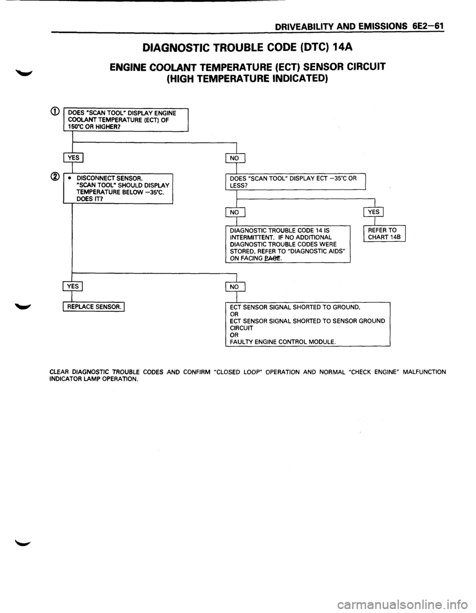
Numbers below refer to circled numbers on the diagnostic chart.
CD Checks to see if Diagnostic Trouble Code (DTC) was set as result of hard failure or intermittent condition.
DTC 14A will set if:
• The engine has been running for at least 3 minutes.
• Signal Voltage indicates a engine coolant temperature above 15o•c (302.F).
® This test simulates conditions for DTC 148. lfthe ECM recognizes the open circuit (high voltage), and displays
a low temperature, the ECM and wiring are OK.
Diagnostic Aids:
A "Scan tool" reads engine temperature in degrees Celsius.
After the engine is started, the temperature should rise steadily to about so·c, then stabilize, when the thermostat
opens.
If the engine has been allowed to cool to an ambient temperature (overnight), engine coolant temperature and
Intake Air Temperature (IAT) may be checked with a "Scan tool" and should read close to each other.
When a
DTC 14A is set, the ECM will turn "ON" the engine cooling fan.
A
DTC 14A will result if GRY /8LK wire is shorted to ground.
If DTC 14A is intermittent, refer to Section "8".
ENGINE
COOLANT
TEMPERATURE SENSOR. (LOCATED AT REAR OF ENGINE
BELOW
INTAKE
MANIFOLD
ASSEMBLY) ENGINE
HARNESS CONNECTOR(GREEN) L----------<~---GRY/BLK ENGINE HARNESS
CONNECTOR (GRN)
L__ ___ T_O~M(~A-P-~-~-------GRY
SENSOR
NOTICE: IT
MAY BE NECESSARY TO REMOVE THE INTAKE
MANIFOLD TO ACCESS COOLANT SENSOR ON DOHC ENGINE.
Fig. 6E2-35
ENGINE CONTROL MODULE(ECM)
ECT SENSOR SIGNAL
SENSOR GROUND
•
Page 757 of 1928
DRIVEABILITV AND EMISSIONS 6E2-61
DIAGNOSTIC TROUBLE CODE (DTC) 14A
ENGINE COOLANT TEMPERATURE (ECT) SENSOR CIRCUIT
(HIGH TEMPERATURE INDICATED)
(D DOES •scAN TOOL• DISPLAY ENGINE COOLANT TEMPERATURE (ECT) OF 150"C OR HIGHER?
@ • DISCONNECT SENSOR. ·sCAN TOOL • SHOULD DISPLAY TEMPERATURE BELOW -3s•c. DOES IT?
DIAGNOSTIC TROUBLE CODE 141S INTERMITTENT. IF NO ADDITIONAL DIAGNOSTIC TROUBLE CODES WERE STORED, REFER TO "DIAGNOSTIC AIDS" ON FACING fA81:.
ECT SENSOR SIGNAL SHORTED TO GROUND, OR ECT SENSOR SIGNAL SHORTED TO SENSOR GROUND CIRCUIT OR FAULTY ENGINE CONTROL MODULE.
CLEAR DIAGNOSTIC TROUBLE CODES AND CONFIRM "CLOSED LOOP" OPERATION AND NORMAL "CHECK ENGINE" MALFUNCTION INDICATOR LAMP OPERATION.
Page 758 of 1928
6E2~62 DRIVEABILITY AND EMISSIONS
DIAGNOSTIC TROUBLE CODE (DTC) 148
ENGINE COOLANT TEMPERATURE (ECT) SENSOR CIRCUIT
(LOW TEMPERATURE INDICATED)
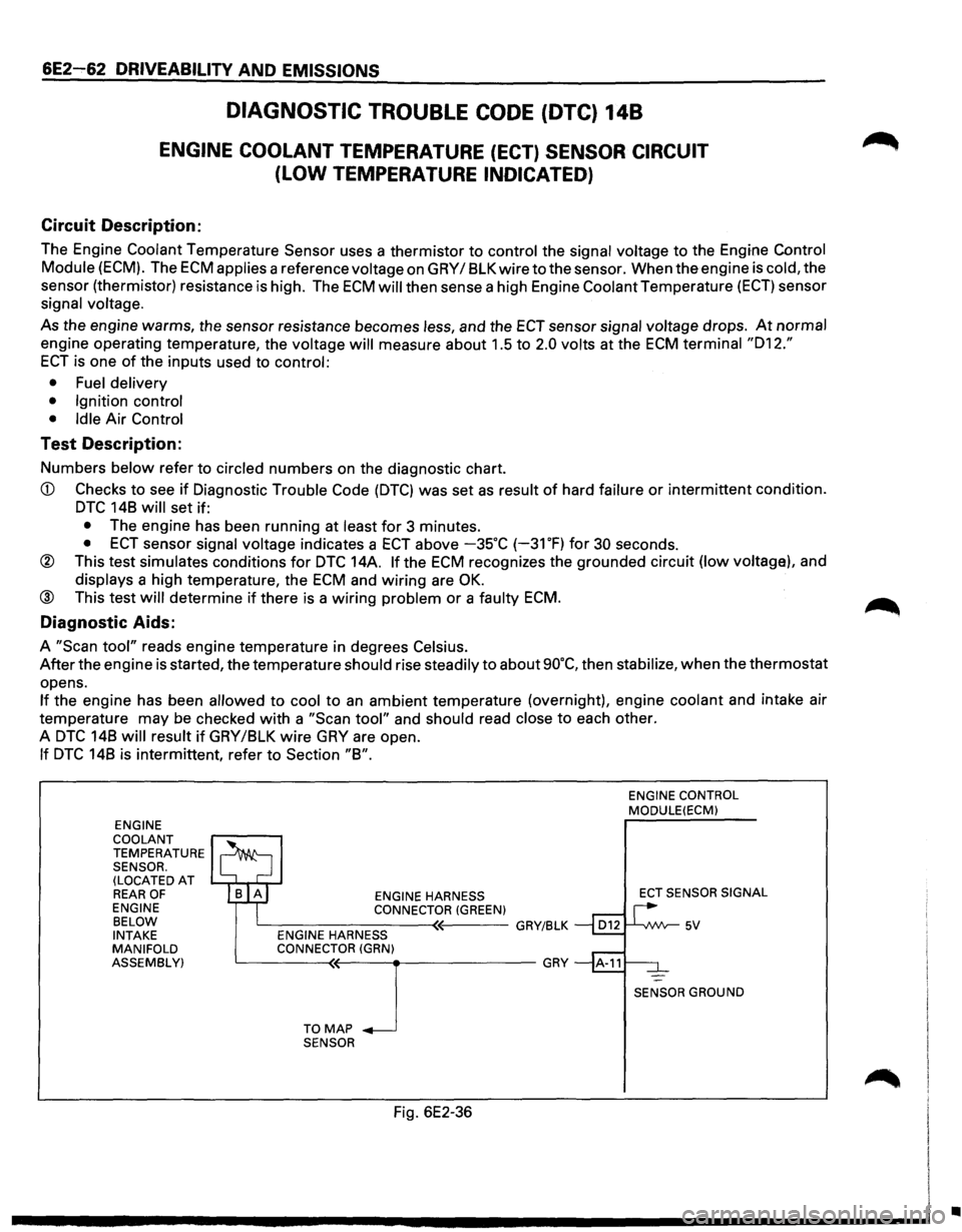
Circuit Description:
The Engine Coolant Temperature Sensor uses a thermistor to control the signal voltage to the Engine Control
Module (ECM). The ECM applies a reference voltage on GRY I 8LK wire to the sensor. When the engine is cold, the
sensor (thermistor) resistance
is high. The ECM will then sense a high Engine Coolant Temperature (ECT) sensor
signal
voltage.
As the engine warms, the sensor resistance becomes less, and the ECT sensor signal voltage drops. At normal
engine operating temperature, the voltage will measure about 1.5 to 2.0 volts at the ECM terminal "012."
ECT is one of the inputs used to control:
• Fuel delivery
• Ignition control
• Idle
Air Control
Test Description:
Numbers below refer to circled numbers on the diagnostic chart.
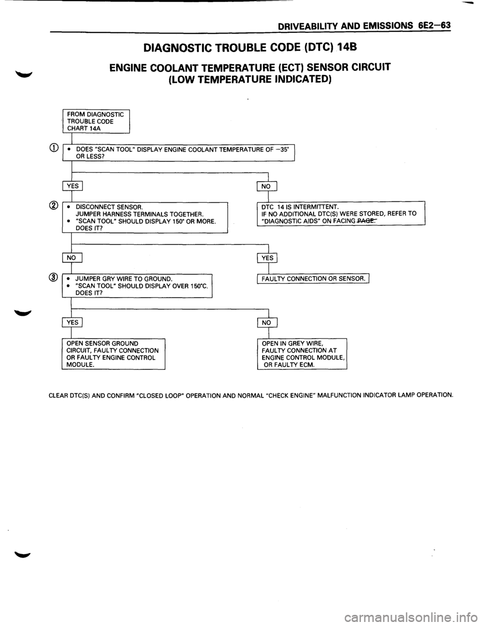
CD Checks to see if Diagnostic Trouble Code (DTC) was set as result of hard failure or intermittent condition.
DTC 148 will set if:
• The engine has been running at least for 3 minutes.
• ECT sensor signal voltage indicates a ECT above -35°C (-31 OF) for 30 seconds.
® This test simulates conditions for DTC 14A. If the ECM recognizes the grounded circuit (low voltage), and
displays a high temperature, the ECM and wiring are OK.
@ This test will determine if there is a wiring problem or a faulty ECM.
Diagnostic Aids:
A "Scan tool" reads engine temperature in degrees Celsius.
After the engine is started, the temperature should rise steadily to about 90°C, then stabilize, when the thermostat
opens.
If the engine has been allowed to cool to an ambient temperature (overnight), engine coolant and intake air
temperature may be checked
with a "Scan tool" and should read close to each other.
A
DTC 148 will result if GRY/8LK wire GRY are open.
If DTC 148 is intermittent, refer to Section "8".
ENGINE
COOLANT
TEMPERATURE SENSOR.
(LOCATED AT REAR OF ENGINE
BELOW
INTAKE
MANIFOLD
ASSEMBLY) ENGINE
HARNESS
CONNECTOR (GREEN) c__---------<~'----GRY/BLK ENGINE HARNESS
CONNECTOR (GRN)
~---T-0--<'M<(--A-P_J ___________ GRY
SENSOR
Fig. 6E2-36
ENGINE CONTROL MODULE(ECM)
ECT
SENSOR SIGNAL
SENSOR GROUND
•
Page 759 of 1928
DRIVEABILITV AND EMISSIONS 6E2-63
DIAGNOSTIC TROUBLE CODE (DTC) 148
ENGINE COOLANT TEMPERATURE (ECT) SENSOR CIRCUIT
(LOW TEMPERATURE INDICATED)
FROM DIAGNOSTIC
TROUBLE CODE CHART 14A
I • DOES "SCAN TOOL" DISPLAY ENGINE COOLANT TEMPERATURE OF -35"l OR LESS?
I
~ $
• DISCONNECT SENSOR. DTC 14 IS INTERMITTENT. JUMPER
HARNESS TERMINALS TOGETHER. IF NO ADDITIONAL DTC(S) WERE STORED, REFER TO
• "SCAN TOOL" SHOULD DISPLAY 150" OR MORE. "DIAGNOSTIC AIDS" ON FACING~ DOES IT?
I
$ c$
• JUMPER
GRY WIRE TO GROUND. FAUL TV CONNECTION OR SENSOR. I • "SCAN TOOL" SHOULD DISPLAY OVER 150"C.
DOES IT?
I
~ $
OPEN SENSOR GROUND OPEN IN GREY WIRE,
CIRCUIT, FAUL TV CONNECTION FAUL TV CONNECTION AT OR FAUL TV ENGINE CONTROL ENGINE CONTROL MODULE,
MODULE. OR FAUL TV ECM.
CLEAR DTC(S)
AND CONFIRM "CLOSED LOOP" OPERATION AND NORMAL "CHECK ENGINE" MALFUNCTION INDICATOR LAMP OPERATION.
Page 760 of 1928
/
6E2-64 DRIVEABILITY AND EMISSIONS
Circuit Description:
DIAGNOSTIC TROUBLE CODE (DTC) 21A
THROTTLE POSITION (TP) SENSOR CIRCUIT
(SIGNAL
VOLTAGE HIGH)
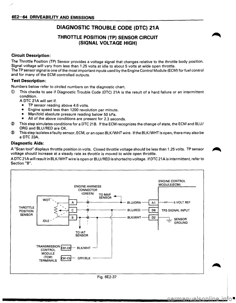
The Throttle Position (TP) Sensor provides a voltage signal that changes relative to the throttle body position.
Signal voltage
will vary from less than 1.25 volts at idle to about 5 volts at wide open throttle.
The
TP sensor signal is one of the most important inputs used by the Engine Control Module (ECM) for fuel control
and
for many of the ECM controlled outputs.
Test Description:
Numbers below refer to circled numbers on the diagnostic chart.
A
DTC 21 A will set if.
• TP sensor reading above 4.6 volts.
• Engine speed less than 1200 revolution per minute.
• Manifold absolute pressure reading below 50 kPa.
• All of the above conditions are present for 2.3 seconds.
® This step simulates conditions for a DTC 21 B. If the ECM recognizes the change of state, the ECM and BLU/
ORG and BLU/RED are OK.
® This step isolates a faulty sensor, ECM, or an open BLK/WHTwire. If the BLK/WHTis open, there may also be
a
DTC 23A.
Diagnostic Aids:
A "Scan tool" displays throttle position in volts. Closed throttle voltage should be less than 1.25 volts. TP sensor ~
voltage should increase at a steady rate as throttle is moved to wide open throttle.
A
DTC 21Awill result in BLK/WHTwire is open or BLU/RED is shorted to voltage. If DTC 21A is intermittent, refer to
Section "8".
THROTILE
POSITION
SENSOR
WOT',
IDLE"' ENGINE
HARNESS
CONNECTOR
(GREEN) TO MAP
TOIAT SENSOR SENSOR
TRANSMISSION~ BLK/WHT CONTROL ~-
MODULE
(TCM)
~ GRY/BLK -----.J TERMINALS ~
Fig. 6E2-37
ENGINE CONTROL
MODULE(ECM)
SENSOR
-GROUND
•