ISUZU TROOPER 1995 Workshop Manual
Manufacturer: ISUZU, Model Year: 1995, Model line: TROOPER, Model: ISUZU TROOPER 1995Pages: 1928
Page 1351 of 1928
CHASSIS ELECTRICAL 8-161
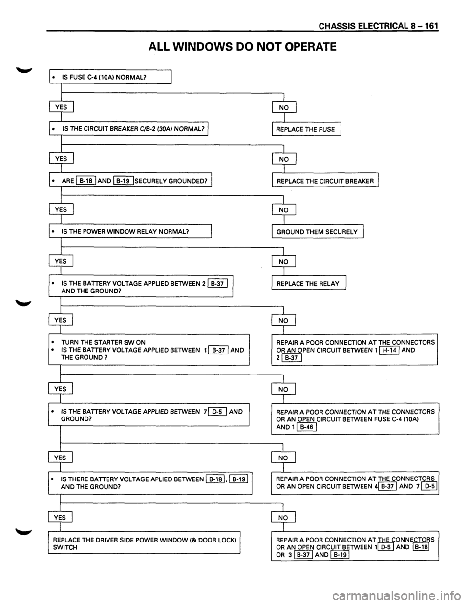
ALL WINDOWS DO NOT OPERATE
• IS FUSE C-4 (10A) NORMAL? I
I
YES I NO I
I
• IS THE CIRCUIT BREAKER C/B-2 (30Al NORMAL? I REPLACE THE FUSE I
I
YES I NO I
I
• ARE ~AND I B-19 !sECURELY GROUNDED? J REPLACE THE CIRCUIT BREAKER I
I
YES I NO I
I
• IS THE POWER WINDOW RELAY NORMAL? I GROUND THEM SECURELY I
I
YES I NO I
I
• IS THE BATTERY VOLTAGE APPLIED BETWEEN 21 B-37 I J REPLACE THE RELAy I AND THE GROUND?
I
YES I NO
I
I
• TURN THE STARTER SW ON REPAIR A POOR CONNECTION AT THE CONNECTORS
• IS THE BATTERY VOLTAGE APPLIED BETWEEN 11 B-371 AND OR AN OPEN CIRCUIT BETWEEN 1 CB:BJ AND THE GROUND? 2IB-37I
I
YES j NO I
I
• IS THE BATTERY VOLTAGE APPLIED BETWEEN 7[@ AND REPAIR A POOR CONNECTION AT THE CONNECTORS
GROUND? OR AN OPEN CIRCUIT BETWEEN FUSE C-4 (10A)
AND 11 B-461
I
YES I NO J
I
• IS THERE
BATTERY VOLTAGE APLIED BETWEEN I B-1sl,l B-191 REPAIR A POOR CONNECTION AT THE CONNECTORS
AND THE GROUND? OR AN OPEN
CIRCUIT BETWEEN 41 B-371 AND 71 D-51
I
YES I NO I
I
REPLACE THE DRIVER SIDE POWER WINDOW I& DOOR LOCK) 1 SWITCH REPAIR A POOR CONNECTION AT IHE TONNiCTOiS OR AN OPEN
CIRCUIT BETWEEN 1 D-5 AND B-18
OR sl B-371 AND I B-191
Page 1352 of 1928
8-162 CHASSIS ELECTRICAL
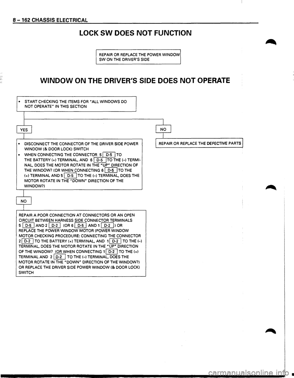
LOCK SW DOES NOT FUNCTION
REPAIR OR REPLACE THE POWER WINDOW SW ON THE DRIVER'S SIDE
WINDOW ON THE DRIVER'S SIDE DOES NOT OPERATE
• START CHECKING THE ITEMS FOR "ALL WINDOWS DO
NOT OPERATE" IN THIS SECTION
YES
I
• DISCONNECT THE CONNECTOR OF THE DRIVER SIDE POWER
WINDOW (&DOOR LOCK) SWITCH
•
WHEN CONNECTING THE CONNECTO~ TO
THE BATTERY(+) TERMINAL, AND 6 ~HE(-) TERMI
NAL, DOES
THE MOTOR ROTATE IN THE "UP" DIRECTION OF
THE WINDOW? (OR WHEN CONNECTING 6 ~TO THE
(+)TERMINAL AND 5 [QTITO THE(-) TERMINAL, DOES THE
MOTOR ROTATE IN THE "DOWW DIRECTION OF THE
WINDOW?)
NO
j
REPAIR A POOR CONNECTION AT CONNECTORS OR AN OPEN
CIRCUIT BETWEEN HARNESS SIDE CONNECTOR TERMINALS
5 [ill AND 2 ~ (OR 6 [QlJ AND 1 [Q}J) OR
REPLACE THE POWER WINDOW MOTOR (POWER WINDOW
MOTOR CHECKING PROCEDURE: CONNECTING THE CONNECTOR
2 (QTI TO THE BATIERY (+)TERMINAL, AND 1 ~TO THE(-)
TERMINAL, DOES THE MOTOR ROTATE IN THE "UP" DIRECTION
OF THE WINDOW? (OR WHEN CONNECTING 1 [[_[]TO THE(+)
TERMINAL AND 2 [ill TO THE(-) TERMINAL, DOES THE
MOTOR ROTATE IN THE "DOWN" DIRECTION OF THE WINDOW?)
OR REPLACE THE DRIVER SIDE POWER WINDOW (&DOOR LOCK)
SWITCH
I
I NO I
I
l REPAIR OR REPLACE THE DEFECTIVE PARTS .I
•
Page 1353 of 1928
CHASSIS ELECTRICAL 8 -163
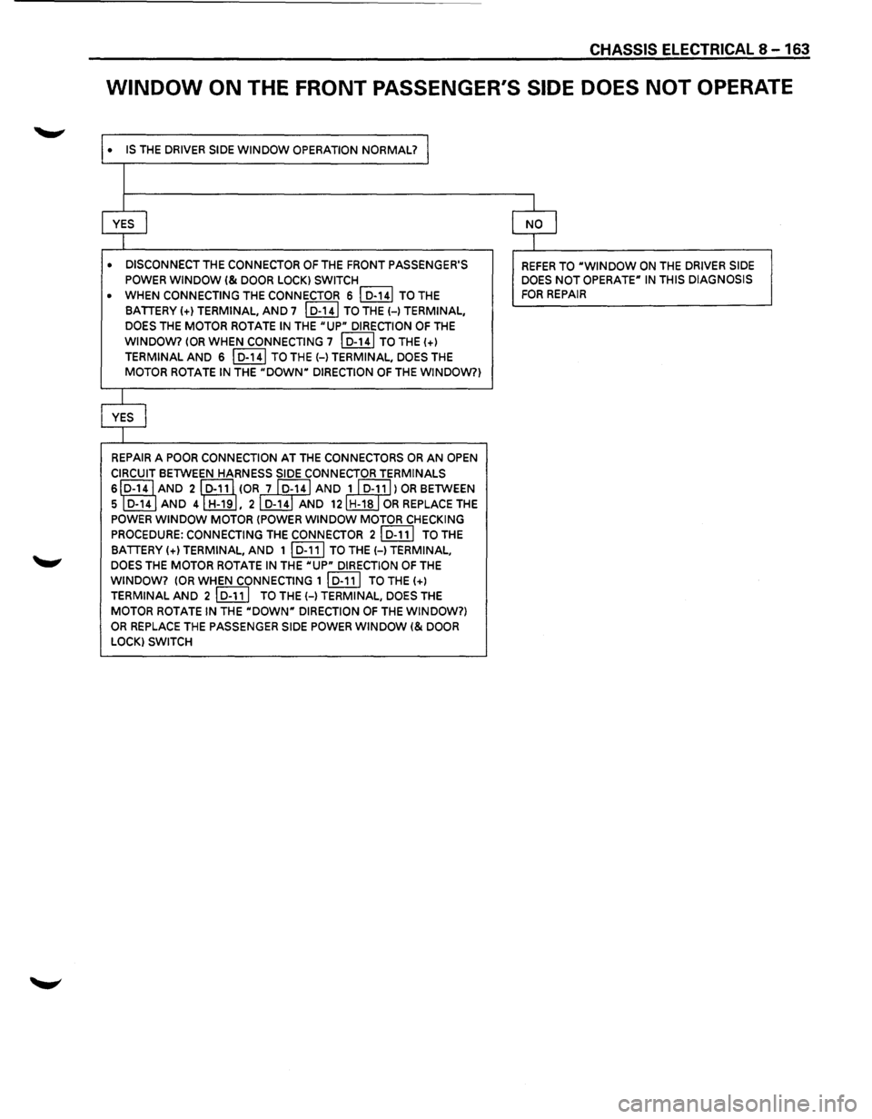
WINDOW ON THE FRONT PASSENGER'S SIDE DOES NOT OPERATE
• IS THE DRIVER SIDE WINDOW OPERATION NORMAL? I
YES I
• DISCONNECT THE CONNECTOR OF THE FRONT PASSENGER'S
POWER WINDOW I& DOOR LOCK) SWITCH
•
WHEN CONNECTING THE CONNECTOR 6 I D-141 TO THE
BATIERY (+)TERMINAL, AND7 I D-141 TO THE H TERMINAL,
DOES
THE MOTOR ROTATE IN THE "UP" DIRECTION OF THE
WINDOW? lOR WHEN CONNECTING 7 I D-141 TO THE(+)
TERMINAL AND 6 I D-141 TO THE(-) TERMINAL, DOES THE
MOTOR ROTATE IN THE "DOWN" DIRECTION OF THE WINDOW?)
YES
I
REPAIR A POOR CONNECTION AT THE CONNECTORS OR AN OPEN
CIRCUIT
BETWEEN HARNESS SIDE CONNECTOR TERMINALS
slr14I(ND 2 (Q;1il (OR~ AND ~)OR BETWEEN
5 D-14
AND 4 ~. 2 ~NO 12lliJ.ilQR REPLACE THE
POWER
WINDOW MOTOR (POWER WINDOW MOTOR CHECKING
PROCEDURE: CONNECTING
THE CONNECTOR 21 D-111 TO THE
BATIERY (+)TERMINAL, AND 1 ~ TO THE H TERMINAL,
DOES
THE MOTOR ROTATE IN THE "UP" DIRECTION OF THE
WINDOW? lOR WHEN CONNECTING 1 (Q;11] TO THE(+)
TERMINAL AND 2 I D-111 TO THE H TERMINAL, DOES THE
MOTOR ROTATE IN THE "DOWN" DIRECTION OF THE WINDOW?)
OR REPLACE THE PASSENGER SIDE POWER WINDOW I& DOOR
LOCK) SWITCH
I
NO I
I
REFER TO "WINDOW ON THE DRIVER SIDE DOES NOT OPERATE" IN THIS DIAGNOSIS
FOR REPAIR
Page 1354 of 1928
8-164 CHASSIS ELECTRICAL
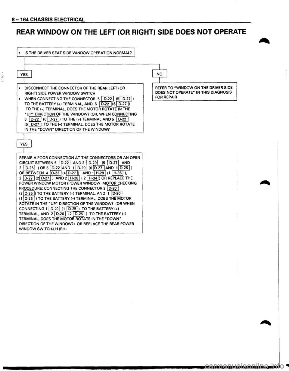
REAR WINDOW ON THE LEFT (OR RIGHT) SIDE DOES NOT OPERATE
• IS THE DRIVER SEAT SIDE WINDOW OPERATION NORMAL?
• DISCONNECT
THE CONNECTOR OF THE REAR LEFT (OR
RIGHT) SIDE POWER WINDOW SWITCH
•
WHEN CONNECTING THE CONNECTOR 5 ~ (5 D-27 )
TO THE BATTERY(+) TERMINAL, AND 6 ~(6 D-27 )
TO THE(-) TERMINAL, DOES THE MOTOR ROTATE IN THE
•upn DIRECTION OF THE WINDOW? (OR, WHEN CONNECTING
6 II D-221 (61 D-271) TO THE(+) TERMINAL AND 5 I D-22 I
(5 D-27 ) TO THE(-) TERMINAL, DOES THE MOTOR ROTATE
IN
THE uDOWNH DIRECTION OF THE WINDOW?
REFER TO ·wiNDOW ON THE DRIVER SIDE
DOES NOT OPERATE• IN THIS DIAGNOSIS
FOR REPAIR
..
Page 1355 of 1928
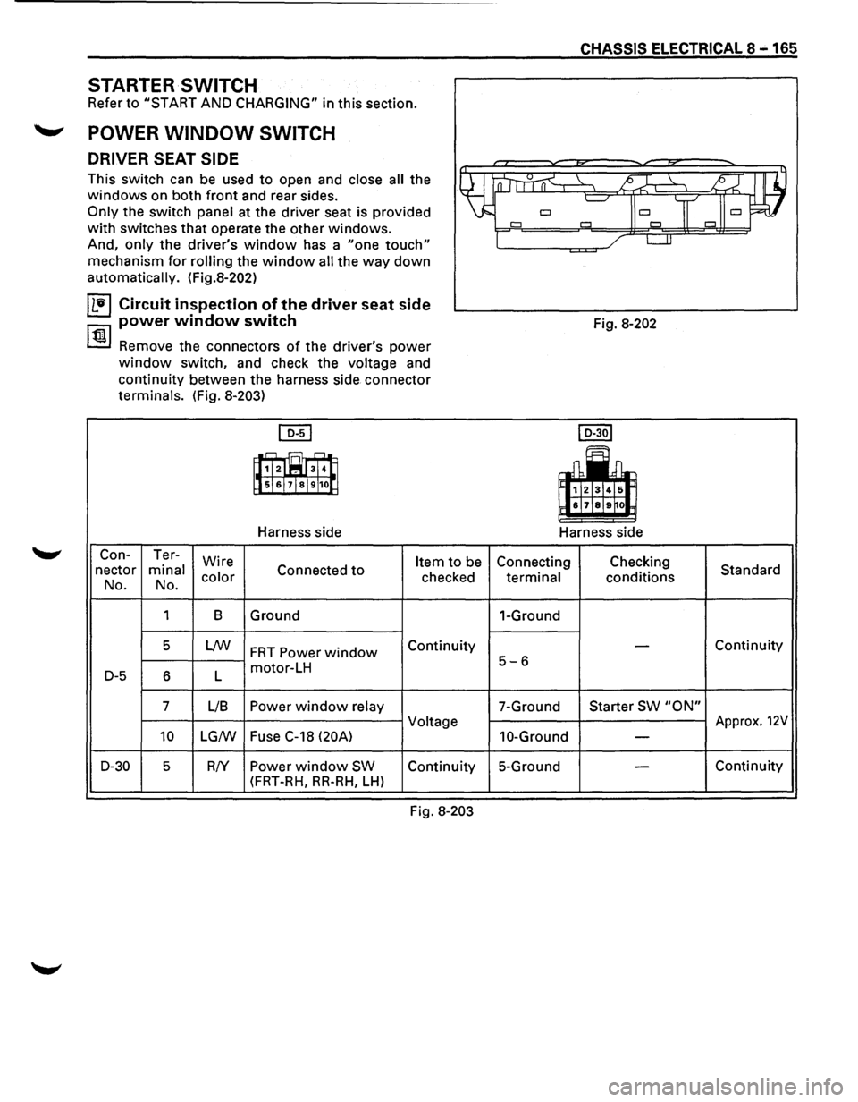
STARTER SWITCH
Refer to "START AND CHARGING" in this section .
........,. POWER WINDOW SWITCH
DRIVER SEAT SIDE
This switch can be used to open and close all the
windows on both front and rear sides.
Only the switch panel at the driver seat is provided
with switches that operate the other windows.
And, only the driver's window has a "one touch"
mechanism for rolling the window all the way down
automatically. (Fig.8-202)
IL'ti'l Circuit inspection of the driver seat side
power window switch
~ Remove the connectors of the driver's power
window switch, and check the voltage and
continuity between the harness side connector
terminals. (Fig.
8-203)
[QI]
~B
lls!&!7!sl9 100
Harness side
Con- Ter-
Wire
Item to be
nectar minal Connected to
No. No. color checked
1 8 Ground
5
LNJ FRT Power window Continuity
D-5 6 L motor-LH
7 L/8
Power window relay
Voltage
10 LG/W Fuse
C-18 (20A)
D-30
5 R!Y Power window SW Continuity
(FRT-RH,
RR-RH, LH)
Fig. 8-203
CHASSIS ELECTRICAL 8-165
Fig. 8-202
I D-30l
~~~
&171&19~0
Harness side
Connecting Checking
Standard
terminal conditions
1-Ground
-Continuity
5-6
7-Ground Starter SW "ON"
Approx. 12V
10-Ground -
5-Ground -Continuity
Page 1356 of 1928
8-166 CHASSIS ELECTRICAL
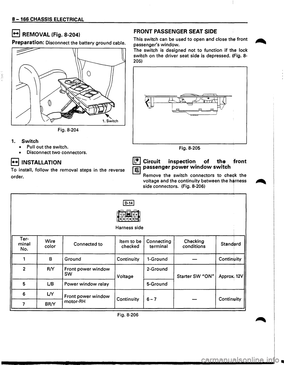
1+•1 REMOVAL (Fig. 8-204) FRONT PASSENGER SEAT SIDE
Preparation: Disconnect the battery ground cable. This
switch can be used to open and close the front ~
passenger's window.
Fig.
8-204
1. Switch
• Pull out the switch.
• Disconnect two connectors.
B INSTALLATION
The switch is designed not to function if the lock
switch on the driver seat side is depressed. {Fig. 8-
205)
Fig. 8-205
To install, follow the removal steps in the reverse
order.
IL•I Circuit inspection of the front
1 tW,j passenger power window switch
Remove the switch connectors to check the
voltage and the continuity between the
h~rness
side connectors. (Fig. 8-206) !
I D-141
., = ,._
~3f4l:l j1s]sJ7jsl9J1~
Harness side
Ter-
I
minal Wire
Connected to Item to be Connecting Checking Stand~rd
No. color
checked terminal conditions
1
8 Ground Continuity 1-Ground -Contin~ity
2 R!Y Front power window 2-Ground
sw Voltage Starter SW "ON" Approx; 12V
5 LIB Power window relay 5-Ground
6
L!Y Front power window Continuity 6-7 -Continuity
7
BR/Y motor-RH
Fig.
8-206
•
Page 1357 of 1928
CHASSIS ELECTRICAL 8-167
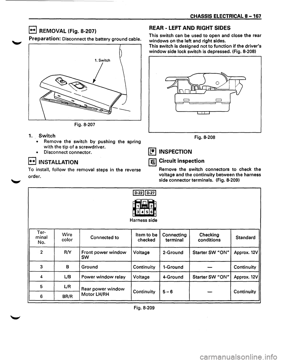
B REMOVAL (Fig. 8-207) REAR -LEFT AND RIGHT SIDES
Preparation: Disconnect the battery ground cable. This
switch can be used to open and close the rear
windows on the left and right sides.
This switch is designed not
to function if the driver's
window side lock switch is depressed. (Fig. 8-208)
1. Switch
I
--
Fig. 8-207
1.
Switch
• Remove the switch by pushing the spring
with the tip of a screwdriver.
• Disconnect connector. Fig.
8-208 (1!] INSPECTION
I++IJNSTALLATION
I til Circuit inspection
To install, follow the removal steps in the reverse Remove the switch connectors to check the
order. voltage and the continuity between the harness
'-"' side connector terminals. (Fig. 8-209)
I D-2211 D-271
m
Harness side
Ter- Wire
Item to be Connecting Checking
minal Connected to Standard
No. color
checked terminal conditions
2
RN Front power window Voltage 2-Ground
Starter SW "ON" Approx. 12V
sw
3 B
Ground Continuity
1-Ground -Continuity
4 LIB Power window relay Voltage 4-Ground
Starter SW "ON" Approx. 12V
5 L/R Rear power window Continuity 5-6 -Continuity
6 BR/R Motor LH/RH
Fig. 8-209
Page 1358 of 1928
8-168 CHASSIS ELECTRICAL
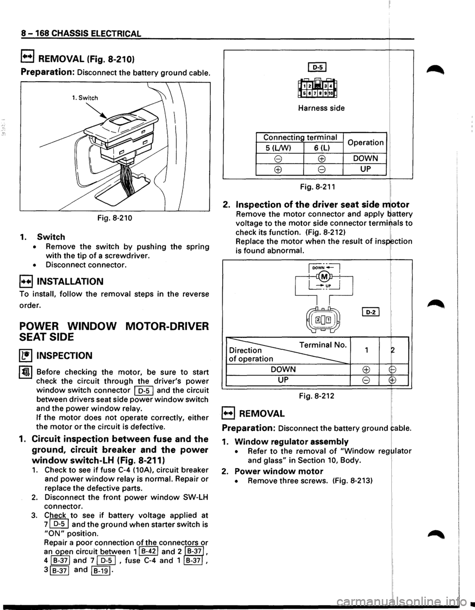
1+•1 REMOVAL (Fig. 8-210)
Preparation: Disconnect the battery ground cable.
Fig.
8-210
1. Switch
• Remove the switch by pushing the spring
with the tip of a screwdriver.
• Disconnect connector.
B INSTALLATION
To install, follow the removal steps in the reverse
order.
POWER WINDOW MOTOR-DRIVER
SEAT SIDE
(b!] INSPECTION
lt!l Before checking the motor, be sure to start
check the circuit
through the driver's power
window switch connector I]]] and the circuit
between drivers seat side
power window switch
and
the power window relay.
If the motor does not operate correctly, either
the motor or the circuit is defective.
1. Circuit inspection between fuse and the
ground, circuit breaker and the power
window switch-LH (Fig. 8-211)
1. Check to see if fuse C-4 (10A), circuit breaker
and
power window relay is normal. Repair or
replace the defective parts.
2. Disconnect the front power window SW-LH
connector.
3. Check to see if battery voltage applied at
71 D-5 I and the ground when starter switch is
"ON" position.
Repair a
poor connection of the connectors or
aj opel circuit between 1! B-421 and 2 "B-37!1,
4 B-37 and 71 D-5 I , fuse C-4 and 1 B-37 ,
3IB-37I and IB-191·
Harness side
Connecting
terminal
5 (Lf\N) 6 (L) Operation
DOWN
UP
2. Inspection oft:~;i:~, seat side j
1 otor
Remove the motor connector and apply attery
voltage
to the motor side connector term als to
check its function. (Fig. 8-212)
Replace the
motor when the result of insp ~ction
is found abnormal.
~~ , .-1M .
Llf'~
I
I
~
~
~o. 1 ~ D
0 p I
DOWN ~ (9
UP 8 (tJ
Fig. 8-212
B REMOVAL
Preparation: Disconnect the battery ground able.
1. Window regulator assembly
• Refer to the removal of "Window reg lator
and glass" in Section 10, Body.
2. Power window motor
• Remove three screws. (Fig. 8-213)
•
Page 1359 of 1928
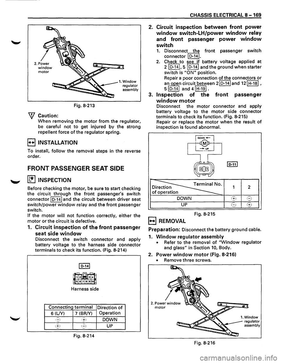
2. Power window motor
W Caution:
Fig. 8-213
1. Window
regulator
assembly
When removing the motor from the regulator,
be careful
not to get injured by the strong
repellent force of the regulator spring.
B INSTALLATION
To install, follow the removal steps in the reverse
order.
FRONT PASSENGER SEAT SIDE
~ INSPECTION
Before checking the motor, be sure to start checking
the circuit
through the front passenger's switch
connector
JD-141 and the circuit between driver seat
switch/power
window relay and the front passenger
switch.
If the motor will not function correctly, either the
motor or the circuit is defective.
1. Circuit inspection of the front passenger
seat side
window
Disconnect the switch connector and apply
battery voltage
to the harness side connector
terminals
to check its function. (Fig. 8-214)
I o-141
_.ar; -=-_r;._ 11,T z"tiM 3T ,11 ll slsl71&1911o[l
Harness side
Connecting terminal
Direction
of
6(LN) 7 (BR/Y) Operation
I::) '+I DOWN
\:!:) I=) UP
Fig.
8-214
CHASSIS ELECTRICAL 8-169
2. Circuit inspection between front power
window switch-LH/power window relay
and
front passenger power window
switch
1. Disconnect the front passenger switch
connector
ID-141.
2. Check to see if battery voltage applied at
2ID-14I,5ID-14I andthegroundwhenstarter
switch is "ON" position.
Repair a
poor connection of the connectors or
aj opT circuit between 2ID-14Iand 12IH-1BI,
5 D-14 and 4JH-19J.
3. Inspection of the front passenger
window motor
Disconnect the motor connector and apply
battery voltage
to the motor side connector
terminals
to check its function. (Fig. 8-215)
Repair
or replace the motor when the result of
inspection is found abnormal.
D.~Terminal No. 1rect1on
of operation
DOWN
UP
Fig. 8-215
B REMOVAL
1 2
8
8
Preparation: Disconnect the battery ground cable.
1. Window regulator assembly
• Refer to the removal of "Window regulator
and
glass" in Section 10, Body.
2. Power window motor (Fig. 8-216)
• Remove three screws.
2. Power window motor
Fig. 8-216
Page 1360 of 1928
8-170 CHASSIS ELECTRICAL
W Caution:
When removing the regulator from the motor,
be careful not to get injured by the strong force
of the regulator spring.
B INSTALLATION
To install, follow the removal steps in the reverse
order.
REAR-LEFT SIDE
~ INSPECTION
Before checking the motor, be sure to start checking
the rear window switch (left) connector lo-221 and
the circuit between
front power window switch-LH/
power window relay and the rear power window
switch-LH.
If the motor will not operate correctly, either the
motor or the circuit is defective.
1. Circuit inspection of the rear window
switch circuit -left side
3. Inspection of the rear window motor -
left side
Disconnect the motor connector and apply ~
battery voltage to the motor side connector
terminals to check its function. (Fig. 8-218)
Repair or replace the motor, when the result of
inspection is found abnormal.
@J
p
&)
lo-2ol
0
~
0 1 2 1rect1on
of operation
DOWN El 8
UP E) G
Fig. 8-218 Disconnect the switch connector and apply
battery voltage to the harness side connector
terminals to check its function. (Fig. 8-217) 1••1 REMOVAL
Harness side
Connecting
terminal Direction of
5 (L/R) 6 (BR/R) Operation
1+1 ,_) UP
1-) DOWN
Fig. 8-217
2. Circuit inspection between front power
window switch-LH/power window relay
and rear power window left side switch
1. Disconnect the rear power window switch-LH
connector lo-221.
2. Check to see if battery voltage applied at
41 D-221, 2 I D-221 and the ground when starter
switch is "ON" position.
Repair a
poor connection of the connectors or
an~n circuit between 4ID-22I and 1IH-29I,
2 ~and 2 IH-281.
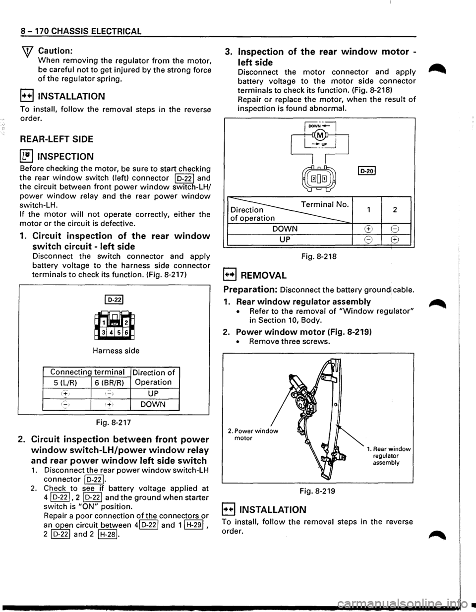
Preparation: Disconnect the battery ground1cable.
1. Rear window regulator assembly
• Refer to the removal of "Window regulator"
in Section 10, Body.
2. Power window motor (Fig. 8-219)
• Remove three screws.
Fig.
8-219
B INSTALLATION
1. Rear window regulator
assembly
To install, follow the removal steps in the reverse
order.
•