ISUZU TROOPER 1995 Workshop Manual
Manufacturer: ISUZU, Model Year: 1995, Model line: TROOPER, Model: ISUZU TROOPER 1995Pages: 1928
Page 1321 of 1928
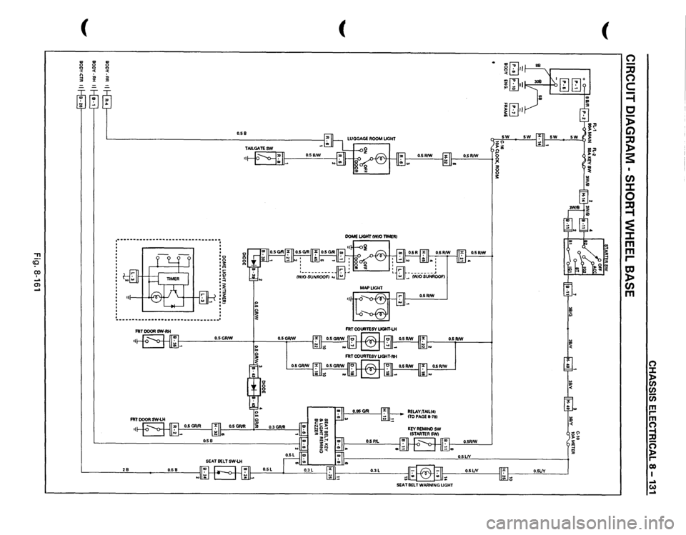
, co CX) . ... Ol ...
( --.. ..
.. 0 0 0 ~
~
0 <
!:l
,;,
,;,
"'
X
,
------------------------------~
. :g :~ ,c •"' ,x . ... :~ ·-•!: om :2!
--------------------------------·
FRT
DOOR
SW-RH
O.SGR/W
2B
O.SB
O.SB/W
~ C> ~
O.SGR/W
( ,,o.J-.r.~ FRT COURTESY
UGHT-LH
FRT
COURTESY
UGHT-RH
O.SR/W
O.SR!W
RELAV;TAILI•I ITO PAGE
8-781
KEY
REMIND
SW
CST ARTER
SW1
O.SR/W O.SR/W
O.SR/W
O.SR/W O.SlJY
8 !:
0 ., "'[;] ~ .;. ,,
mf"Yl ~liJ•Ik-
lb I ill
ill?j
~~., !~
~ :~ I h
.. !!' "'
II
O.SlJY
II~ I
O.SLJV
I
~ 0
SEAT
BELT
WARNING
LIGHT
(
(") -::0 (") c =i c 5> C) ::0 )> s I CJ) :I: 0 ~ ~ :I: m
m r-to )> CJ) m I I I
() :::t )> en
en (i) m r-m () -1 :c 0 )> r-QO I ..a w ..a
Page 1322 of 1928
![ISUZU TROOPER 1995 Workshop Manual 8-132 CHASSIS ELECTRICAL
CONNECTOR LIST
[E] mJ I B-111
~
-
mmm
6 8
I B-241 []1] I B-261 I B-391 I B-391 ISWBI
6l~JJ
--c(Q:) u~~~~~9 WI
~
~
I H-321 (GRADEs I
Fig. 8-162
•](/img/61/57183/w960_57183-1321.png "ISUZU TROOPER 1995 Workshop Manual 8-132 CHASSIS ELECTRICAL
CONNECTOR LIST
[E] mJ I B-111
~
-
mmm
6 8
I B-241 []1] I B-261 I B-391 I B-391 ISWBI
6l~JJ
--c(Q:) u~~~~~9 WI
~
~
I H-321 (GRADEs I
Fig. 8-162
•")
8-132 CHASSIS ELECTRICAL
CONNECTOR LIST
[E] mJ I B-111
~
-
mmm
6 8
I B-241 []1] I B-261 I B-391 I B-391 ISWBI
6l~JJ
--c(Q:) u~~~~~9 WI
~
~
I H-321 (GRADEs I
Fig. 8-162
•
Page 1323 of 1928
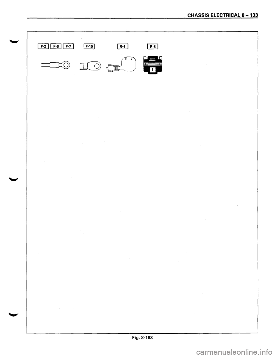
CHASSIS ELECTRICAL 8-133
Fig. 8-163
Page 1324 of 1928
![ISUZU TROOPER 1995 Workshop Manual 8-134 CHASSIS ELECTRICAL
STARTER SWITCH
Refer to "START AND CHARGING" of this section.
DOOR SWITCH
(1!] INSPECTION
Push o
[]:!]
Connector No. IR-11IIB-22IIB-35l Switch
operation Terminal 1 B](/img/61/57183/w960_57183-1323.png "ISUZU TROOPER 1995 Workshop Manual 8-134 CHASSIS ELECTRICAL
STARTER SWITCH
Refer to \"START AND CHARGING\" of this section.
DOOR SWITCH
(1!] INSPECTION
Push o
[]:!]
Connector No. IR-11IIB-22IIB-35l Switch
operation Terminal 1 B")
8-134 CHASSIS ELECTRICAL
STARTER SWITCH
Refer to "START AND CHARGING" of this section.
DOOR SWITCH
(1!] INSPECTION
Push o
[]:!]
Connector No. IR-11IIB-22IIB-35l Switch
operation Terminal 1 Body
Push
Release
Fig. 8-164
I t!ll Check to see if there is any continuity between
the
terminals and the body while operating the
door switch. (Fig. 8-164)
Repair
or replace the switch, when the result of
inspection is found abnormal.
B REMOVAL (FIG. 8-165)
Preparation: Disconnect the battery ground cable.
1. Door switch
Fig. 8-165
1.
Door switch
• Remove the screw.
• Disconnect the connector of the switch.
B INSTALLATION
To install, follow the removal steps in the averse
order.
TAILGATE SWITCH
(b!] INSPECTION
Release
Fig. 8-166
I til Check to see if there is any continuity b tween
the
terminals and the body while operati g the
tailgate switch. (Fig. 8-166)
Repair
or replace the tailgate switch wh n the
result of inspection is found abnormal.
B REMOVAL (FIG. 8-167)
Preparation: Disconnect the battery ground cable.
Fig. 8-167
1.
Tailgate switch
• Remove the screws.
• Disconnect the connector of the switch.
•
Page 1325 of 1928
EJ INSTALLATION
To install, follow the removal steps in the reverse
order.
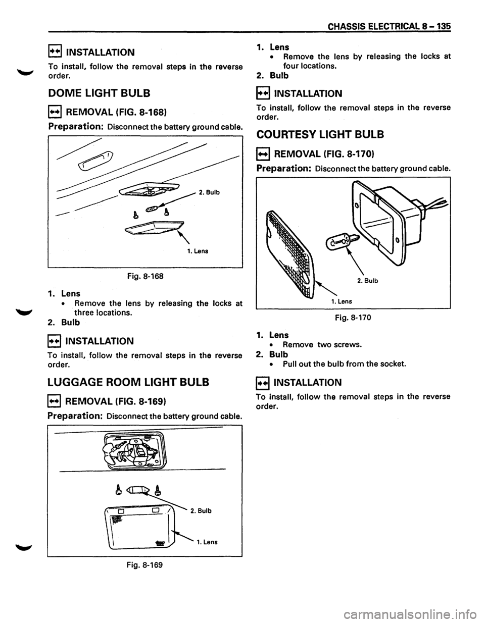
DOME LIGHT BULB
B REMOVAL (FIG. 8-168)
Preparation: Disconnect the battery ground cable.
Fig. 8-168
1. Lens
• Remove the lens by releasing the locks at
"-" three locations.
2. Bulb
B INSTALLATION
To install, follow the removal steps in the reverse
order.
LUGGAGE ROOM LIGHT BULB
B REMOVAL (FIG. 8-169)
Preparation: Disconnect the battery ground cable.
Fig. 8-169
CHASSIS ELECTRICAL 8 -135
1. Lens
• Remove the lens by releasing the locks at
four locations.
2. Bulb
B INSTALLATION
To install, follow the removal steps in the reverse
order.
COURTESY LIGHT BULB
B REMOVAL (FIG. 8-170)
Preparation: Disconnect the battery ground cable.
2. Bulb
Fig. 8-170
1. Lens
• Remove two screws.
2. Bulb
• Pull out the bulb from the socket.
E) INSTALLATION
To install, follow the removal steps in the reverse
order.
Page 1326 of 1928
8 -136 CHASSIS ELECTRICAL
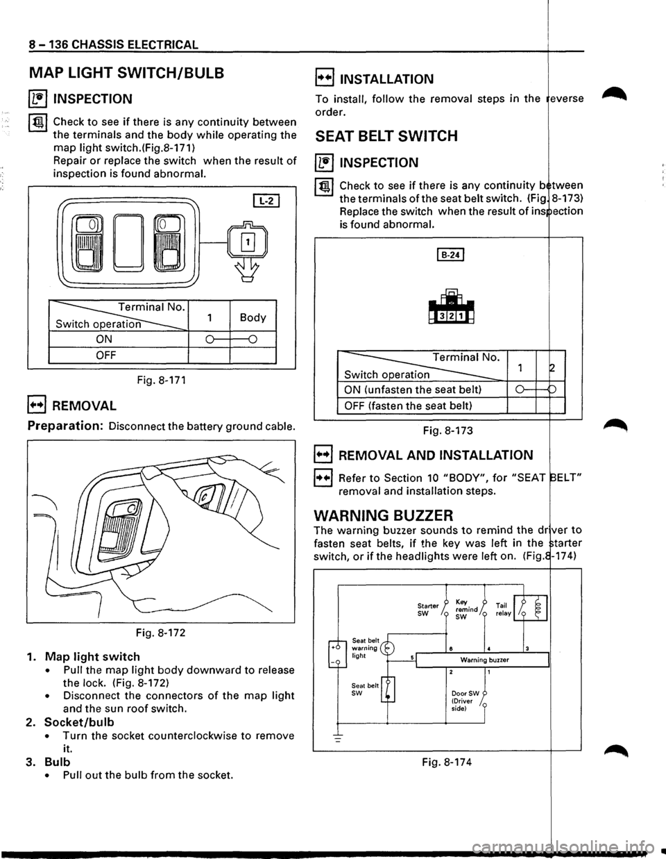
MAP LIGHT SWITCH/BULB
~ INSPECTION
~~~ Check to see if there is any continuity between
the terminals and the body while operating the
map light switch.(Fig.8-171)
Repair
or replace the switch when the result of
inspection is found abnormal.
I" ~ [IT]
ron
0~/~ ~
'
~· 1 Body
n
ON 0 {)
OFF
Fig. 8-171
B REMOVAL
E) INSTALLATION
To install, follow the removal steps in the everse
order.
SEAT BELT SWITCH
~ INSPECTION
I~ l Check to see if there is any continuity b tween
the terminals of the seat belt switch. (Fig 8-173)
Replace the switch when the
result of ins ection
is found abnormal.
Switch operation
ON (unfasten the seat belt)
OFF (fasten the seat belt)
Preparation: Disconnect the battery ground cable. Fig. 8-173
Fig. 8-172
1.
Map light switch
• Pull the map light body downward to release
the
lock. (Fig. 8-172)
• Disconnect the connectors of the map light
and the sun roof switch.
2. Socket/bulb
• Turn the socket counterclockwise to remove
it.
3.
Bulb
• Pull out the bulb from the socket.
B REMOVAL AND INSTALLATION
1++1 Refer to Section 10 "BODY", for "SEAT ELT"
removal and installation steps.
WARNING BUZZER
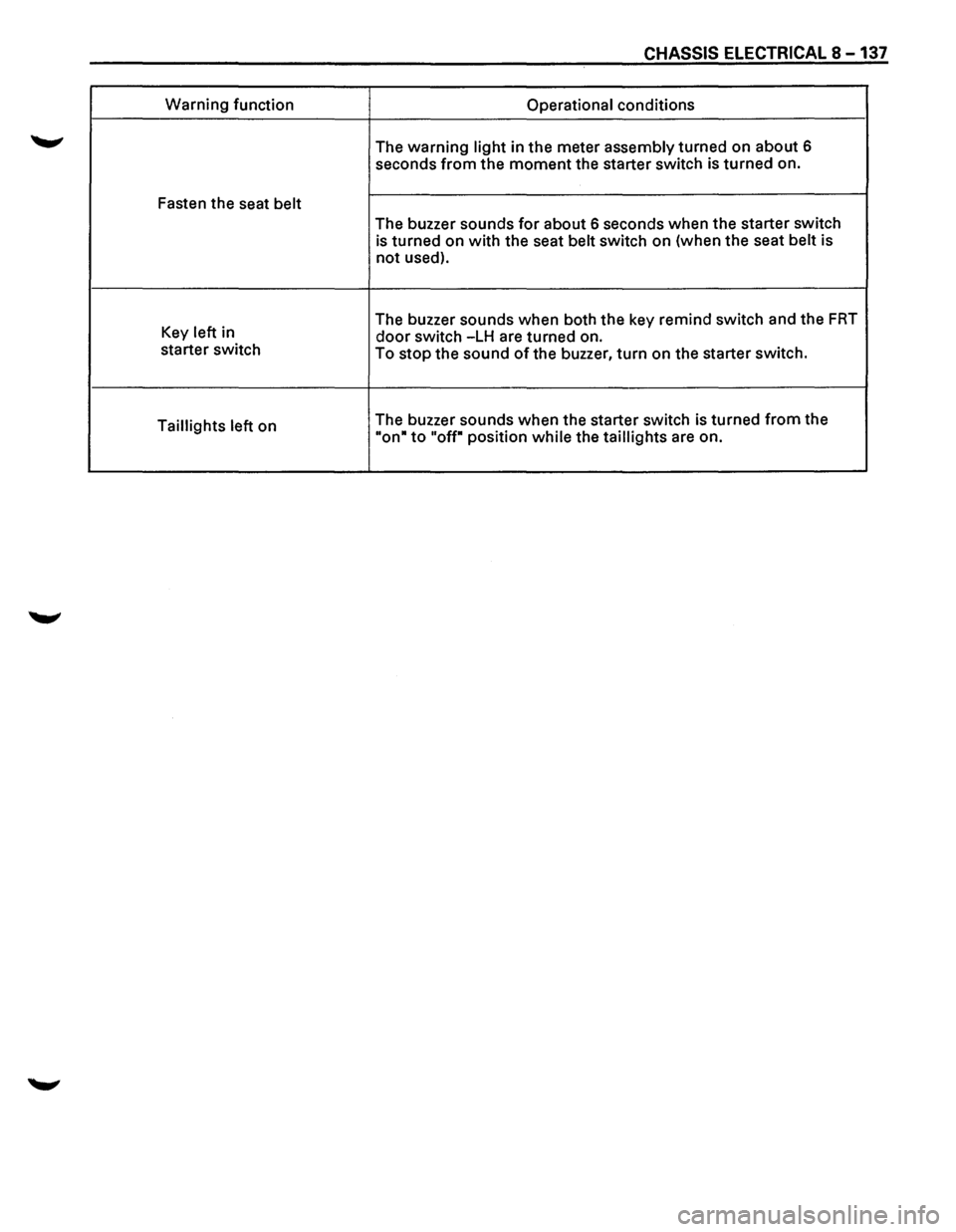
The warning buzzer sounds to remind the dr ver to
fasten seat belts, if the key was left in the tarter
switch,
or if the headlights were left on. (Fig. -174)
Seat belt warning light
Seat belt
sw
Starter sw
8
Warning buzzer
DoorSW (Driver
side)
Fig. 8-174
..
Page 1327 of 1928
CHASSIS ELECTRICAL 8-137
Warning function
Operational conditions
The
warning light in the meter assembly turned on about 6
seconds
from the moment the starter switch is turned on.
Fasten the seat
belt
The buzzer sounds for about 6 seconds when the starter switch
is turned on with the seat belt switch on (when the seat belt is
not used).
Key left in The
buzzer sounds when both the key remind switch and the
FRT
door switch -LH are turned on.
starter switch
To
stop the sound of the buzzer, turn on the starter switch.
Taillights left on The
buzzer sounds when the starter switch is turned
from the
"on• to "off" position while the taillights are on.
Page 1328 of 1928
8-138 CHASSIS ELECTRICAL
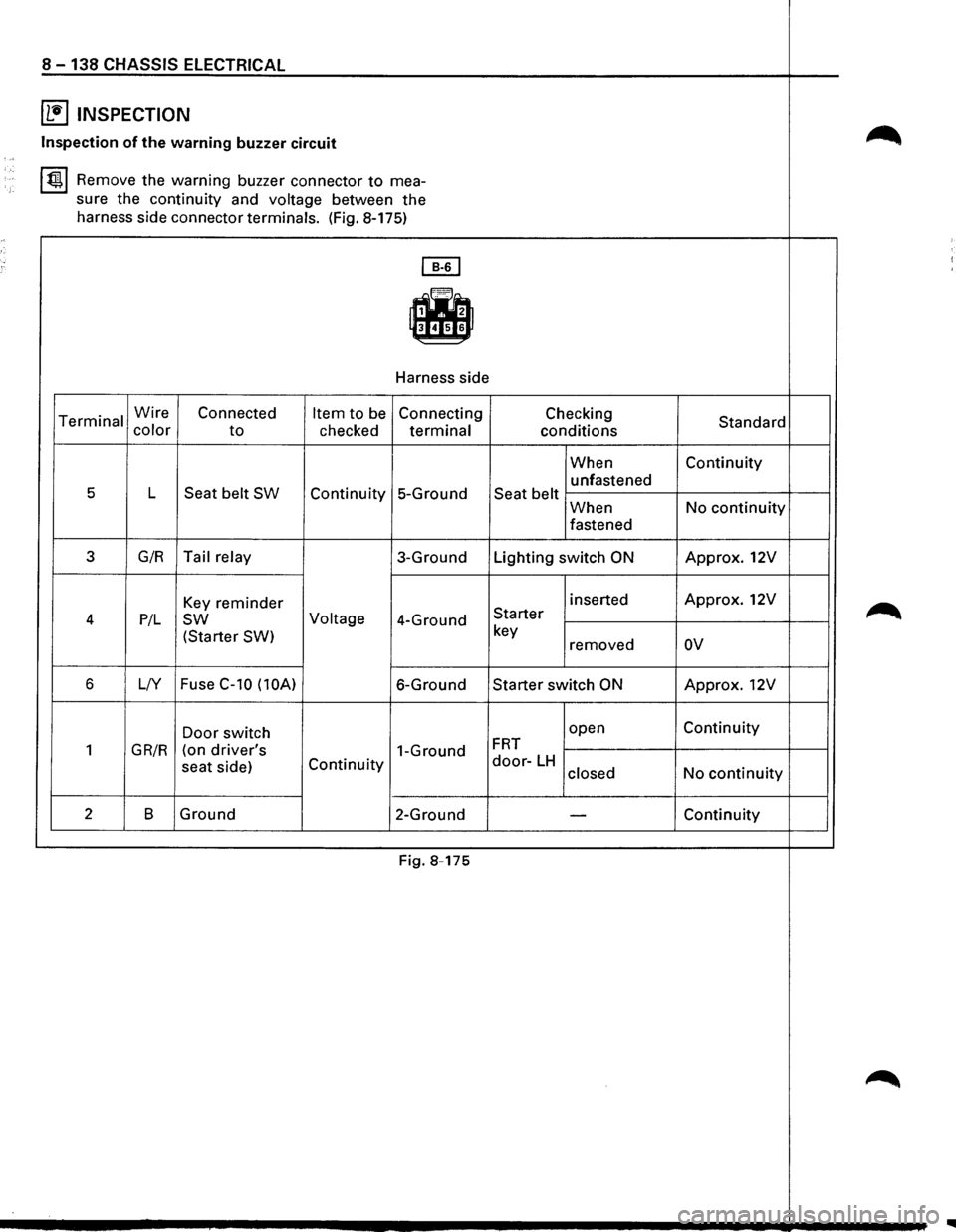
~ INSPECTION
~ Inspection of the warning buzzer circuit ,,,
~ Remove the warning buzzer connector to mea-
sure the continuity and
voltage between the
harness side connector terminals. (Fig. 8-175)
~
-Harness side
Terminal Wire Connected Item to be Connecting Checking Standard color to checked terminal conditions
When Continuity
unfastened
5 L Seat belt SW Continuity 5-Ground Seat belt When No continuity
fastened
3 G/R Tail relay 3-Ground Lighting switch ON Approx. 12V
Key reminder inserted Approx. 12V
~ 4 P/L sw Voltage 4-Ground Starter
(Starter SW)
key
removed ov
6 L/Y Fuse C-10
(lOA) 6-Ground Starter switch ON Approx. 12V
Door switch open Continuity
1 GR/R (on driver's 1-Ground FRT
seat
side) Continuity door-LH No continuity closed
2 B Ground
2-Ground -Continuity
Fig. 8-175
~
Page 1329 of 1928
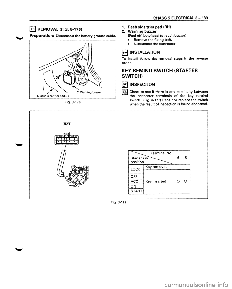
B REMOVAL (FIG. 8-176)
Preparation: Disconnect the battery ground cable.
1. Dash side trim pad (RHl
' 2. Warning buzzer
Fig. 8-176
CHASSIS ELECTRICAL 8-139
1. Dash side
trim pad (RH)
2. Warning buzzer
(Peel off butyl seal to reach buzzer)
• Remove the fixing bolt.
• Disconnect the connector.
E) INSTALLATION
To install, follow the removal steps in the reverse
order.
KEY REMIND SWITCH (STARTER
SWITCH)
~ INSPECTION
I t!tl Check to see if there is any continuity between
the connector terminals of the key remind
switch. (Fig. 8-177) Repair
or replace the switch
when the result
of inspection is found abnormal.
~
6 8
n
y
LOCK Key removed
OFF
ACC Key inserted o-ro
ON
START
Fig. 8-177
Page 1330 of 1928
._, '•'
8 -140 CHASSIS ELECTRICAL
E) REMOVAL AND INSTALLATION E) REMOVAL (FIG. 8-180)
l••l Refer to "START AND CHARGING" in this sec-Preparation: Disconnect the battery ground cable.
tion for starter switch removal and installation
steps.
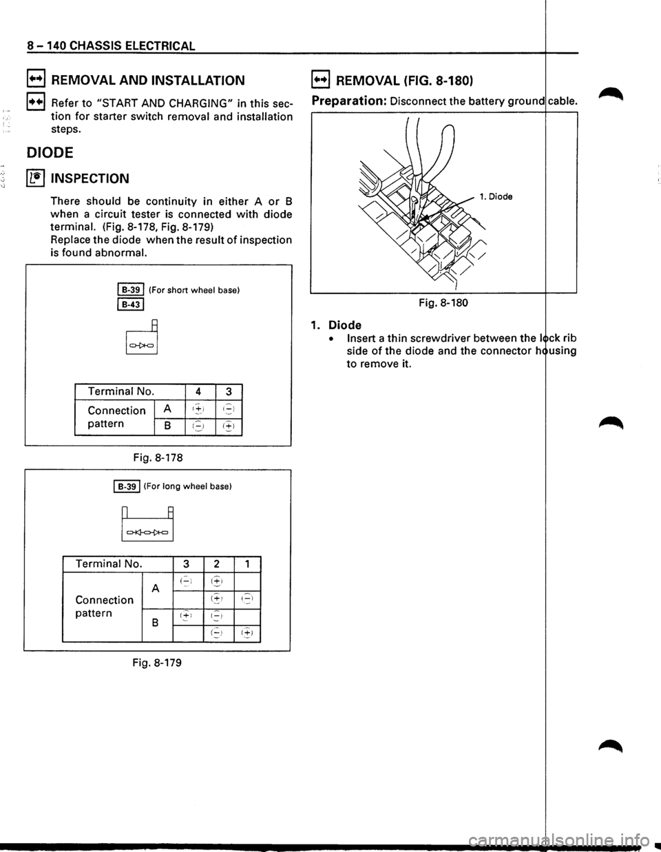
DIODE
~ INSPECTION
There should be continuity in either A or B
when a circuit tester is connected with diode
terminal. (Fig. 8-178, Fig. 8-179)
Replace the diode when the result
of inspection
is found abnormal.
I B-391 (For short wheel base)
I B-431
Terminal No. 4 3
Connection A t'+i i-)
pattern B I.=,J 1+1
Fig.
8-178
I B-391 (For long wheel base)
Terminal No. 3 2
A (-) 1.!,>
Connection (~!
pattern 1+1 {-) B (-!
Fig. 8-179
1
'.-::::1
(~)
Fig. 8-180
1. Diode
• Insert a thin screwdriver between the I ck rib
side
of the diode and the connector h using
to remove it.
..