ISUZU TROOPER 1995 Workshop Manual
TROOPER 1995
ISUZU
ISUZU
https://www.carmanualsonline.info/img/61/57183/w960_57183-0.png
ISUZU TROOPER 1995 Workshop Manual
Page 1371 of 1928
0.51.Ni
H-25
18 H-24
0.850/W
CHASSIS ELECTR1CAL 8-181
1]!\',!I;,R_UJ~-C:.
'
;f-n
~ : 4 '
'
13-0.85 G/V
!
ll: 0: .. "! 0 0
~ ,; §~ ef ~g
• ' '
'
'
~: ~: >o .,, Oo
BODY-FRT II f--------------+-~--------------------~-------__J
Page 1372 of 1928
'· 1
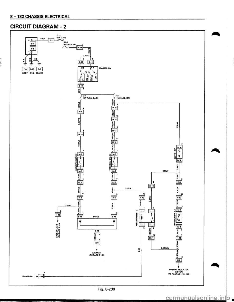
8-182 CHASSIS ELECTRICAL
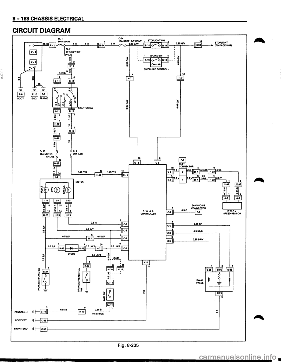
CIRCUIT DIAGRAM - 2
+ o--.J--8'-B:.;./_R--l
B
B
~~P-1oi~ BODY ENG. FRAME
0.8SR/L
E8CMI161 (TO PAGE B-1811
O.SG/8 H-12
~1-'-i.:;.;.J. ...... ""'T.;.;
f
~ ~~--r~':"' IIC
FENDER.ftH II C-3911--------------------------------'
Fig. 8-230
O.SR/V
O.SGR/W
UPSHIFT INDICATOR
I METER) (TO PAGE 8-51, 53, 291)
..
Page 1373 of 1928
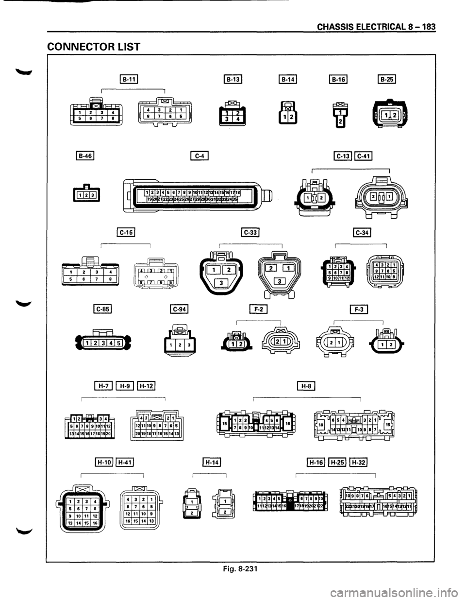
CONNECTOR LIST
~
~
~
' 3
2
1 I~ 8 7 6 5
12 11 10 9
16 15 14 13
CHASSIS ELECTRICAL 8-183
II
' 3 2 1
~ 8171&15 1if1iT10f 9
-= =
Fig. 8-231
Page 1374 of 1928
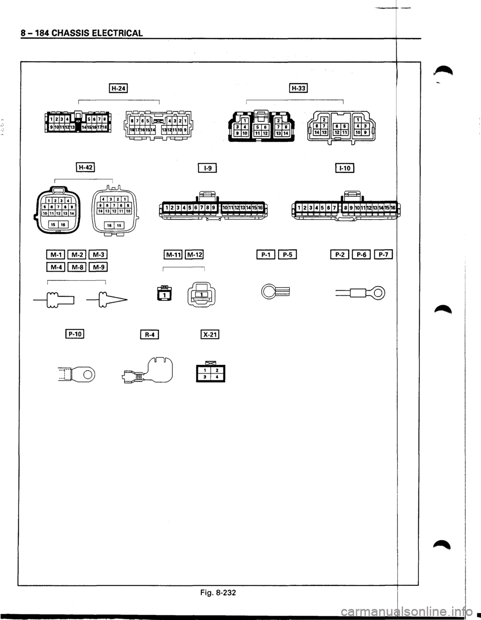
8 -184 CHASSIS ELECTRICAL
~I M-211 M-31
I M-411 M-all M-91
Fig. 8-232
I
-t-
•
Page 1375 of 1928
CHASSIS ELECTRICAL 8-185
REAR WHEEL ANTI-LOCK BRAKE SYSTEM (RWAL)
GENERAL DESCRIPTION
The circuit consists of the starter switch, stoplight switch (vehicle w/o cruise control), brake switch (vehicle
w/cruise control). RWAL controller, RWAL speed sensor, RWAL valve, brake differential switch, 4WD switch,
parking brake
SW, indicator light (RWAL, 4WD, BRAKE), and test connector.
In this system, when the service brake is applied the RWAL controller judges the wheel rotation difference
signals which have been sent from the RWAL speed sensor at the rear axle differential. The anti-lock valves
control
the brake fluid pressure which is applied to the rear wheels to prevent the wheels from locking.
When starting the engine, the RWAL indicator in the instrument panel lights up at the same time as the brake
indicator
to inform the driver that the system is operating normally. (The light goes off after two seconds.)
Refer
to Section 5A3, "RWAL (REAR WHEEL ANTI-LOCK BRAKE SYSTEM)" for detail.
Page 1376 of 1928
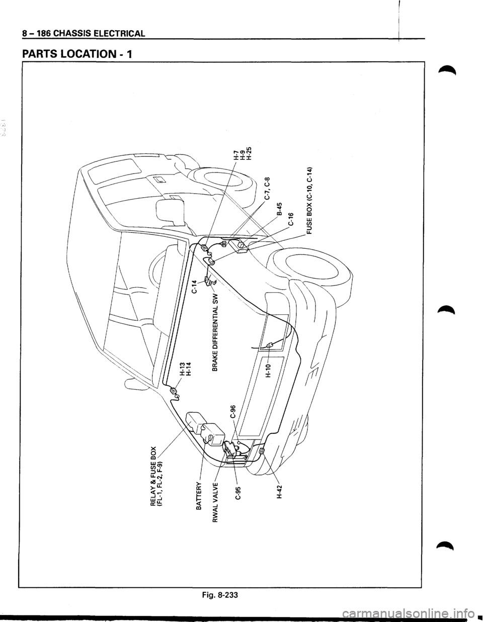
8-186 CHASSIS ELECTRICAL
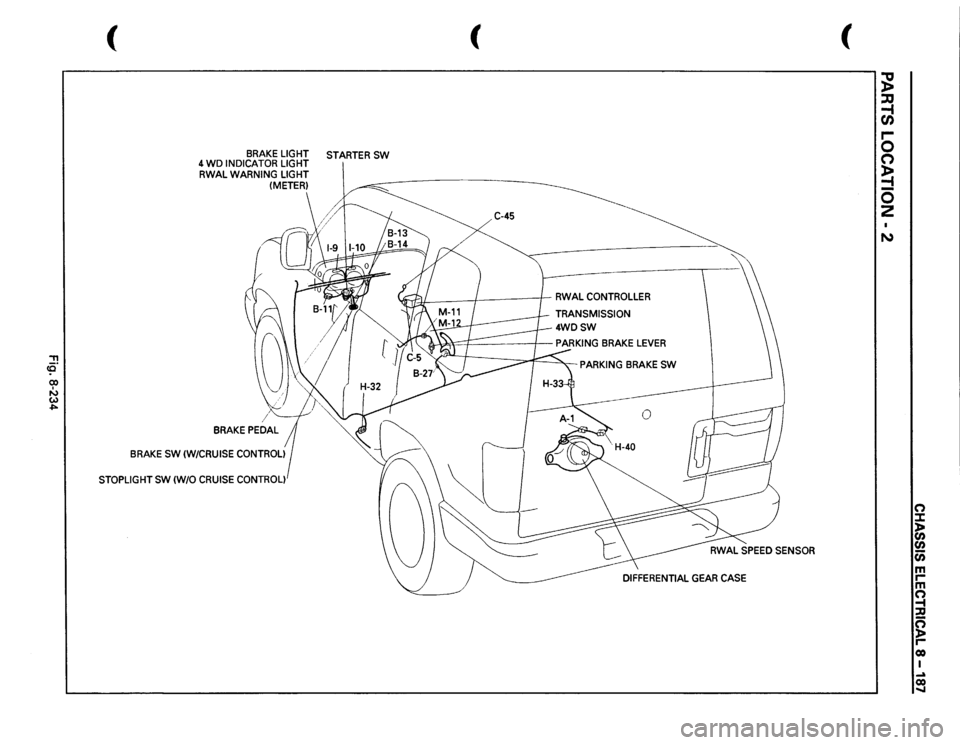
PARTS LOCATION - 1
X 0 Ill w-(/)~ :JU. u.c-~ ~....:. >->-u. a: w
~ ..J• w..J a:!:!; Ill
w > ..J <( > ..J <( 3: a:
Lt'l r--Ol N ±±±
Lt'l ~ u
Fig. 8-233
op u
N ...t ±
~ .-u ci .-
~ X 0 Ill
..
Page 1377 of 1928
::!! (Q 00 I ....., w ..,..
(
BRAKE
LIGHT
STARTER
SW
4 WD
INDICATOR
LIGHT
RWAL
WARNING
LIGHT (METER)
BRAKE
SW
(W/CRUISE
CONTROL)
STOPLIGHT
SW
(W/0
CRUISE
CONTROL)
(
C-45
JfJI:
/
I
RWAL
CONTROLLER
TRANSMISSION
4WDSW
PARKING
BRAKE
SW
(
;g ::JJ -1 en .... 0 0 ~ -0 2 N
n :I: l> en en c;; m rm n -t :a g reo I ~ co .....
Page 1378 of 1928
8-188 CHASSIS ELECTRICAL
CIRCUIT DIAGRAM
Ill Ill
+
B jP-toj~ BODY ENG. FRAME
3
FENOER-LH I I
BODY-FRT II
FRONTEND II
5W
F-9 20AABS
5W
1.25Y/G
METER
H-7
0
0 0
0
0.85 G1V
o I BRAKE SW 4 : ~ ~--~--~
~ ~ CW/CRUISE CONTROLI
12 H-7
Fig. 8-235
10 STOPLIGHT ITO PAGE 8-841
•
Page 1379 of 1928
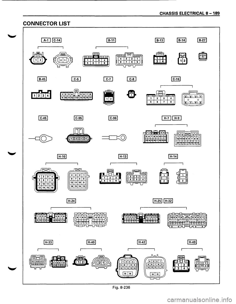
CONNECTOR LIST
13 14 15 16
~
~
..n::8:rl
4 3 2 1 ·~ 8 1 6 5 12 11 10 9
16 15 14 13
CHASSIS ELECTRICAL& -189
Fig. 8-236
Page 1380 of 1928
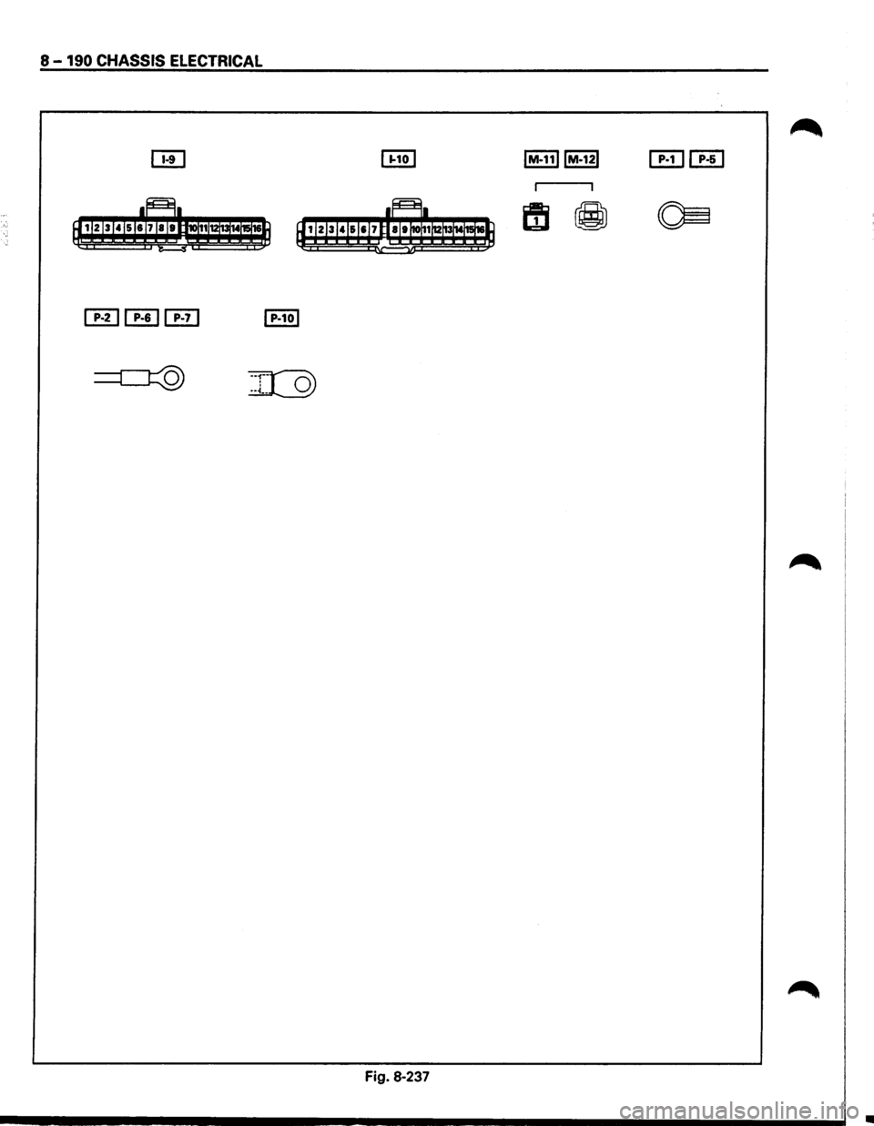
8-190 CHASSIS ELECTRICAL
[EHEJ
'i
Fig. 8-237
•
![ISUZU TROOPER 1995 Workshop Manual 0.51.Ni
H-25
18 H-24
0.850/W
CHASSIS ELECTR1CAL 8-181
1]!\',!I;,R_UJ~-C:.<!_N_1!'9~1-___ ,
;f-n
~ : 4
13-0.85 G/V
!
ll: 0: .. "! 0 0
~ ,; §~ ef ~g
•
~: ~:](/img/61/57183/w960_57183-1370.png "ISUZU TROOPER 1995 Workshop Manual 0.51.Ni
H-25
18 H-24
0.850/W
CHASSIS ELECTR1CAL 8-181
1]!\',!I;,R_UJ~-C:.<!_N_1!'9~1-___ ,
;f-n
~ : 4
13-0.85 G/V
!
ll: 0: .. \"! 0 0
~ ,; §~ ef ~g
•
~: ~:")