ISUZU TROOPER 1995 Workshop Manual
TROOPER 1995
ISUZU
ISUZU
https://www.carmanualsonline.info/img/61/57183/w960_57183-0.png
ISUZU TROOPER 1995 Workshop Manual
Page 1391 of 1928
"T1 ce· 00 I N ~ ~
(
BRAKE
SW
(W/CRUISE
CONTROL)
STOPLIGHT
SW
(W/0
CRUISE CONTROL)
SHIFT
LEVER
" ""'
SHIFT
LOCK
CONTROLLER
""''
RELAY
& FUSE
BOX
(FL-1,
FL-2)
(
STARTERSW
BRAKE
PEDAL
STOP
LIGHT
(LH)
\R-7 "-TRAILER
HARNESS
CONNECTOR
(H-44)
(
;g ~ r-0 0 ~ 5 z
0 :J: ~ en u; m rm ~ :a g reo I N 0 ....
Page 1392 of 1928
<(
8 -202 CHASSIS ELECTRICAL
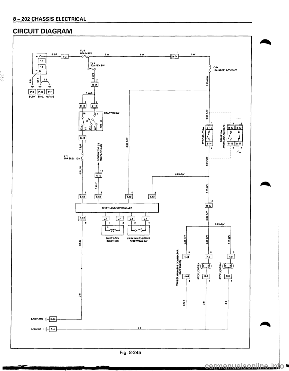
CIRCUIT DIAGRAM
FL-1 + o--t---'8'-'Bi::.:R-'--j P-2 f-----<80)"A~M>i.ATIN ___ _;_5..::W:.__ ______ :.__5:_:W:;_ _____ --I H-14f----_:5_:W:.._ __ ---,
B
B
~~P-1oj~ BODY ENG. FRAME
.. .. 0
.. N
BODY-CTR II B-26 1-------'
FL-2 50A KEYSW
0 !!: 0
SHIFT LOCK SOLENOID PARKING POSmON
DETECTINGSW
C-14 15A STOP, A/T CONT
BODY-RR II R-4 f---------------------'2'-'B'------------4-----4------'
Fig. 8-245
..
Page 1393 of 1928
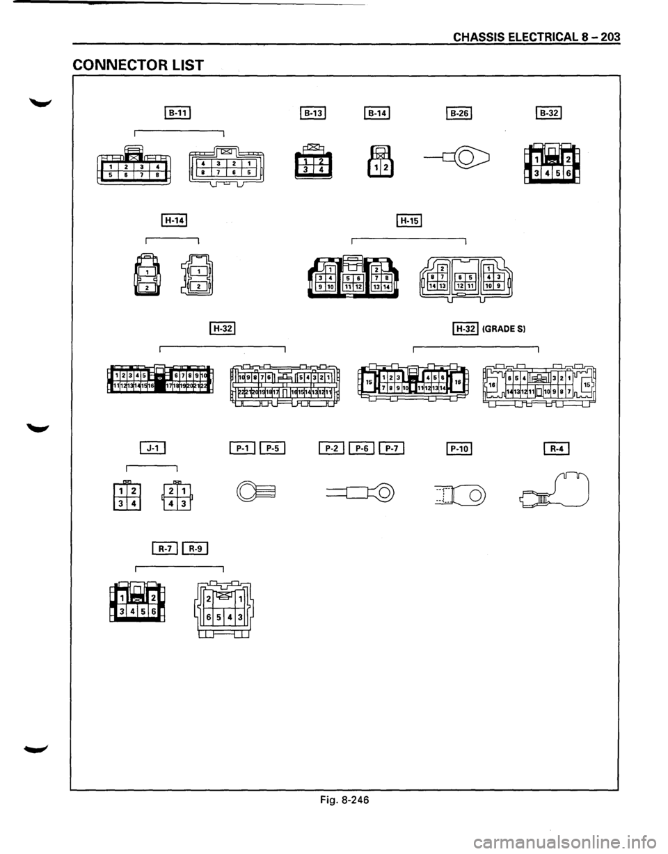
CONNECTOR LIST
~
~
f1i2l
[ill]
~
~
Fig. 8-246
CHASSIS ELECTRICAL 8 -203
~
~
I H-32IIGRADE Sl
Page 1394 of 1928
·;.
8 -204 CHASSIS ELECTRICAL
STARTER SWITCH
Refer to "START AND CHARGING" in this section.
STOPLIGHT
STOPLIGHT SWITCH
BRAKE SWITCH
Refer to "STOPLIGHT AND REAR DEFOGGER" in
,c, this section.
SHIFT LOCK CONTROLLER
Refer to the shift lock controller in Section 7 A
"AUTOMATIC TRANSMISSION."
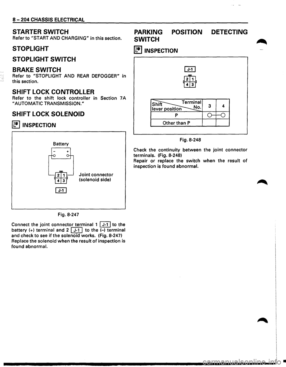
SHIFT LOCK SOLENOID
~ INSPECTION
Fig. 8-247
Joint connector
(solenoid side)
Connect the
joint connector terminal 1 ~to the
battery
(+) terminal and 2 [ill to the (-) terminal
and check to
see if the solenoid works. (Fig. 8-247)
Replace the solenoid when the result
of inspection is
found abnormal.
PARKING POSITION DETECTING
SWITCH
~
(1!]1NSPECTION
l2Ti1
Lill1
Other than P
Fig. 8-248
Check the continuity between the
joint connector
terminals. (Fig. 8-248)
Repair
or replace the switch when the result of
inspection is found abnormal.
I
I I
.............. ~ ................................ -----------------1 .
Page 1395 of 1928
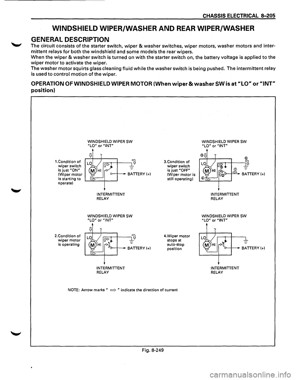
CHASSIS ELECTR1CAL 8-205
WINDSHIELD WIPER/WASHER AND REAR WIPER/WASHER
GENERAL DESCRIPTION
~ The circuit consists of the starter switch, wiper & washer switches, wiper motors, washer motors and inter
mittent relays for both the windshield and some models the rear wipers.
When the
wiper & washer switch is turned on with the starter switch on, the battery voltage is applied to the
wiper motor to activate the wiper.
The washer
motor squirts glass cleaning fluid while the washer switch is being pushed. The intermittent relay
is used
to control motion of the wiper.
OPERATION OF WINDSHIELD WIPER MOTOR (When wiper & washer SW is at "LO" or ''I NT"
position)
1.Condition of wiper switch is just "ON" (Wiper motor is starting to operate)
2.Condition
of wiper motor is operating
WINDSHIELD WIPER SW "LO" or "INT"
o--+--BATTERY(+)
INTERMITTENT RELAY
WINDSHIELD WIPER SW "LO" or "INT"
INTERMITTENT RELAY
3.Condition of
wiper switch
is just "OFF" (Wiper motor is still operating)
4.Wiper
motor stops at auto-stop position
NOTE: Arrow marks " =:> " indicate the direction of current
Fig. 8-249
WINDSHIELD WIPER SW "LO" or "INT"
INTERMITTENT RELAY
WINDSHIELD WIPER SW "LO" or "INT"
o--+--BATTERY(+)
INTERMITTENT RELAY
Page 1396 of 1928
•
., c5" cp N g
)
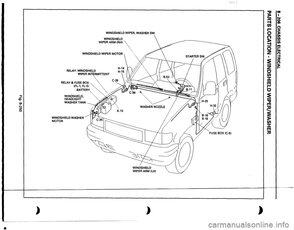
WINDSHIELD
WIPER,
WASHER
SW.
WINDSHIELD
WIPER
ARM
CRH)
WINDSHIELD
WIPER
MOTOR
RELAY:
WINDSHIELD WIPER
INTERMITTENT
RELAY
& FUSE
BOX
~~
(FL-1,
FL-21
\.
BATTERY
\.
"'
',
WINDSHIELD,
""-
. ;;.,
HEADLIGHT WASHER
TANK
WINDSHIELD
WASHER
MOTOR
',
WASHER
NOZZLE
)
;--,-:-.
;g
00 I
~
N 0
en
en n
r-0
X )>
~
(I) (I)
....
c;;
-
m
0
,...
z
m n ......
:E
1:!!
-
n
z
)>
c
,...
en :X: -m r-c ~ -., m :a ...... ~ en :X: m :a
)
Page 1397 of 1928
::!! cc
(
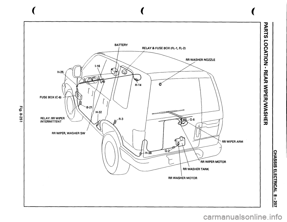
FUSE
BOX
(C-6)
RELAY:
RR
WIPER
INTERMITTENT
RR
WIPER,
WASHER
SW
(
BATTERY
RRWIPERARM
RR
WASHER
MOTOR
(
:: :a -1 U) .... 0 0 ~ 0 z I :a m )> :a :E -., m :a ...... ~ U) :::t m :a
(") ::::1: )> (I)
(I) c;; m rm ~ :u ~ r-eo I N 0 .....
Page 1398 of 1928
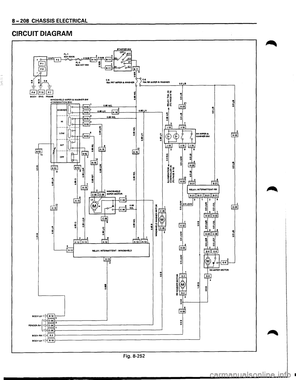
8-208 CHASSIS ELECTRICAL
CIRCUIT DIAGRAM
~~B BODY ENG. FRAME WINDSHIELD WIPER&. WASHER SW
.. ~ N
BODV-LH II
FENDER·RH {::
II
BODY-RR II
BODY-LH II
(COMBINATION SWI
HI
12 H-16
IE. 0 g
~ ¥! ~ Ill ci
C-6 16A FRT WIPER & WASHEflli
~ELAV; INTERMmENT-WINDSHIELD
X-13 2
~ Ill ci
C-1 10A RR WIPER &. WASHER
0.81 LJY
Fig. 8-252
0.6 LJB
.. ~ ci
•
Page 1399 of 1928
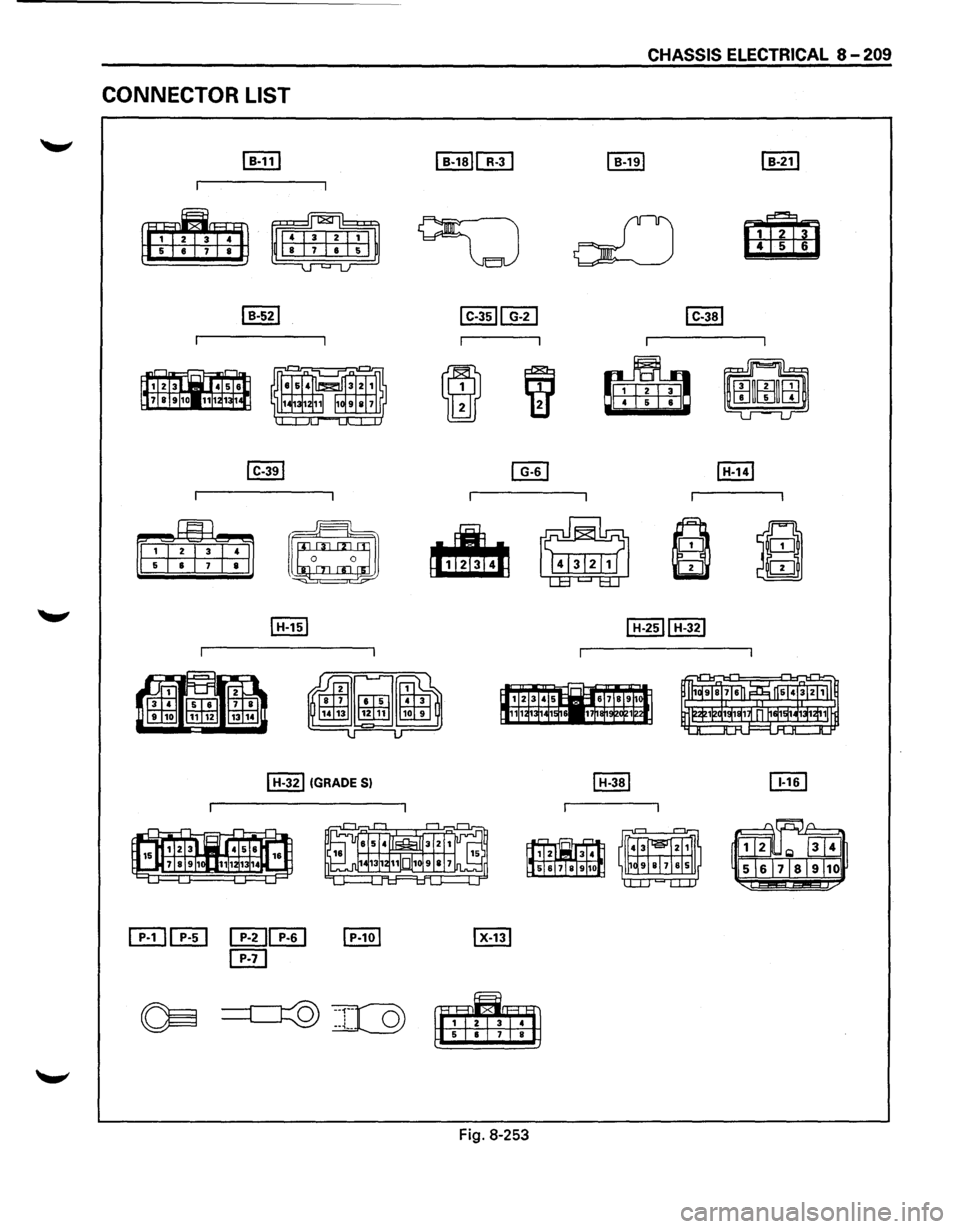
CONNECTOR LIST
~
~
I H-321 (GRADE Sl
~
~
Fig. 8-253
CHASSIS ELECTRICAL 8-209
Page 1400 of 1928
-j.:,
8-210 CHASSIS ELECTRICAL
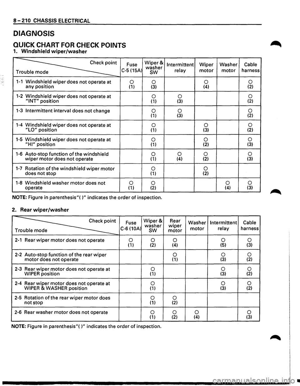
DIAGNOSIS
QUICK CHART FOR CHECK POINTS
1. Windshield wiper/washer
Fuse
~· T C-5 (15A)
1-1 Windshield wiper does not operate at 0 any position (1)
1-2 Windshield wiper does not operate at "INT" position
1-3
Intermittent interval does not change
1-4 Windshield
wiper does not operate at "LO" position
1-5 Windshield
wiper does not operate at
"HI" position
1-6 Auto-stop function
of the windshield wiper motor does not operate
1-7 Rotation of the windshield wiper motor does not stop
1-8 Windshield washer
motor does not 0 operate (1)
Wiper&
washer
sw
0 (3)
0 (1)
0 (1)
0 (1)
0 (1)
0 (1)
0 ( 1)
0 (2)
NOTE:
Figure in parenthesis"( )" indicates the order of inspection.
2. Rear wiper/washer
~
Fuse Wiper&
C-6 (10A) washer T sw
2-1 Rear wiper motor does not operate 0
0 (1) (2)
2-2 Auto-stop function of the rear wiper motor does not operate
2-3 Rear
wiper motor does not operate at 0 WIPER position (1)
2-4 Rear
wiper motor does not operate at 0 WIPER & WASHER position (1)
2-5 Rotation of the rear wiper motor does 0 not stop ( 1)
2-6 Rear
washer motor does not operate 0 ( 1)
NOTE: Figure in parenthesis"( )" indicates the order of inspection.
Intermittent Wiper Washer Cable
relay
motor motor harness
0 0 (4) (2)
0
0 (3) (2)
0
0 (3) (2)
0 0 (3) (2)
0
0 (2) (3)
0
0 0 (4) (2) (3)
0 (2)
0 0 (4)
(3)
Rear
Washer Intermittent Cable wiper motor relay harness motor
0 0 0 (4) (5) (3)
0
0 0 ( 1) (3) (2)
0
0 (3) (2)
0 0 (3) (2)
0 (2)
0
0 0 (2) (4) (3)
•