ISUZU TROOPER 1995 Workshop Manual
Manufacturer: ISUZU, Model Year: 1995, Model line: TROOPER, Model: ISUZU TROOPER 1995Pages: 1928
Page 1341 of 1928
![ISUZU TROOPER 1995 Workshop Manual (b!] INSPECTION OF THE DOOR LOCK
t!l CIRCUIT
~ Check the voltage and the continuity between
the
front door lock (& power window) switch
harness side connector terminals. (Fig. 8-185)
[E)
,](/img/61/57183/w960_57183-1340.png "ISUZU TROOPER 1995 Workshop Manual (b!] INSPECTION OF THE DOOR LOCK
t!l CIRCUIT
~ Check the voltage and the continuity between
the
front door lock (& power window) switch
harness side connector terminals. (Fig. 8-185)
[E)
,")
(b!] INSPECTION OF THE DOOR LOCK
t!l CIRCUIT
~ Check the voltage and the continuity between
the
front door lock (& power window) switch
harness side connector terminals. (Fig. 8-185)
[E)
,, r=1 ,
f.~B
~ slal7lal911o D
TerConnec- minal tor No. Wire
Item to Connecting
color Connected to be
checked terminal
No.
1
7
8
D-5
B
LIB
Ground
Power window
relay
LG/B Lock actuator
(Unlock)
Continuity 1-Ground
Voltage 7-Ground
8-9
CHASSIS ELECTRICAL8 -151
Checking conditions Standard
Continuity
Starter SW
"ON" Approx. 12V
Continuity
9 LG
(There is Continuity 1------.,..--+----------t e
Lock actuator 9-8 -som (Lock) resistance)
10 LG/W Fuse C-18
Voltage 10-Ground Approx.12V
1
(20A)
LG/L Door lock
SW-RH
(Unlock) 1-Ground
Door
lqck SW Unlock Continuity
Lock
No continuity
2 LG/R Door lock 2-Ground Door lock
SW-RH
or
door lock key
SW-LH & RH
Lock Continuity
D-30
3
SW-RH (Lock)
Door lock key
Continuity
SW-LH
& RH
(Lock)
L/Y Door lock key
SW-LH & RH
(Unlock) Unlock
No continuity
3-Ground
Door lock Unlock Continuity
key
SW-LH &
RH Lock No continuity
Fig 8-185
FRONT DOOR LOCK (& POWER
WINDOW) SWITCH-LH
The front door lock (&power window) switch sends
out to each door lock actuator the lock/unlock signals
received
from both door lock switch and door lock
key switch.
Fig 8-186
Page 1342 of 1928
8 -152 CHASSIS ELECTRICAL
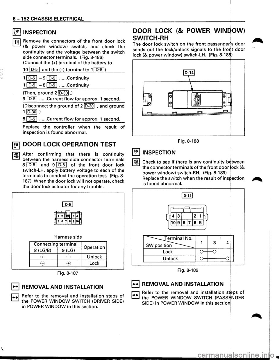
~ INSPECTION
I t!ll Remove the connectors of the front door lock
(& power window) switch, and check the
continuity and the voltage between the switch
side connector terminals. (Fig. 8-186)
(Connect the
(+)terminal of the battery to
10 I D-51 and the(-) terminal to 11 D-51)
11 D-51 -91 D-51 ...... Continuity
1 I D-51 -81 D-51 ...... Continuity
(Then, ground 2ID-30I.)
9 [[[] ...... Current flow for approx. 1 second.
(Disconnect the
ground of 2ID-30l , and ground
1 lD-30l )
8
[]]] ...... Current flow for approx. 1 second.
Replace the
controller when the result of
inspection is found abnormal.
~ DOOR LOCK OPERATION TEST
ltUI After confirming tha~ there is continuity
between the harness s1de connector terminals
8l D-51 and 91 D-51 of the front door lock
switch-LH, apply battery voltage
to each of the
terminals to conduct the operation test. (Fig. 8-
187) When the
door lock will not operate, check
the
door lock actuator for any trouble.
~
E~j
~ sT sT7Islg 10 J
Harness side
Connecting
terminal Operation
8 (LG/8) 9(LG)
,+, ,_, Unlock ~
1-1 1+1 Lock
Fig. 8-187
,._,., REMOVAL AND INSTALLATION
j .. .-j Refer to the removal and installation steps of
the POWER WINDOW SWITCH (DRIVER SIDE)
in POWER WINDOW in this section.
DOOR LOCK (& POWER WINQOW)
SWITCH-RH
i
The door lock switch on the front passenger~s door -
sends out the lock/unlock signals to the fro t door
lock (&power window) switch-LH. (Fig. 8-18 )
Fig. 8-188
~ INSPECTION
lt!ll Check to see if there is any continuity b~tween
the connector terminals of the front door 'ock (&
power window) switch-RH. (Fig. 8-189) 1
Replace the switch when the result of ins~ection ....-...
is found abnormal. ' --.-
SW position
Lock
Unlock
Fig. 8-189
0 REMOVAL AND INSTALLATION ' c:J I
r::J Refer to the removal and installation sfps of
t::.l the POWER WINDOW SWITCH (PASS NGER
SIDE) in POWER WINDOW in this sectio .
•
Page 1343 of 1928
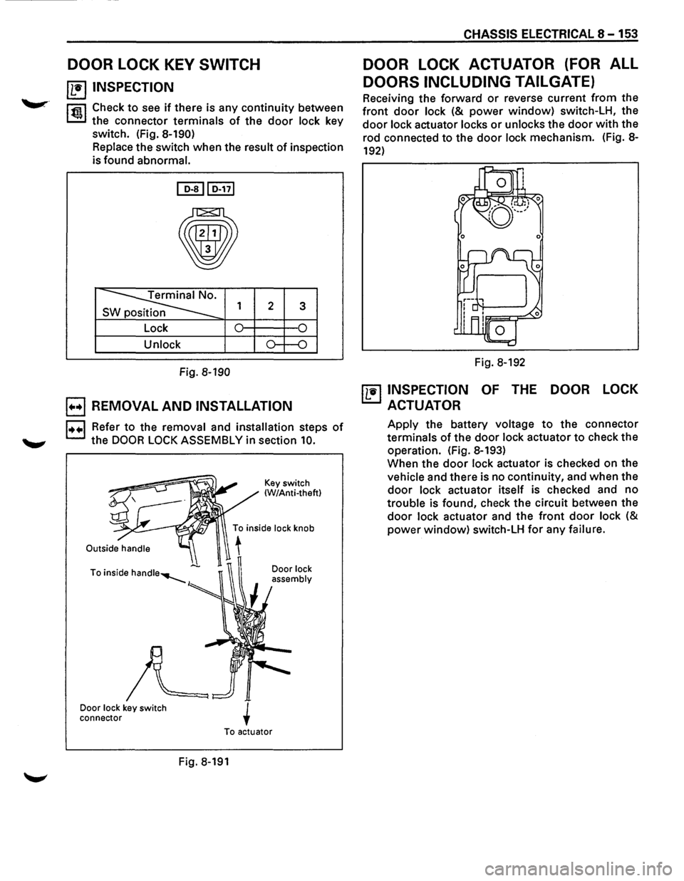
DOOR LOCK KEY SWITCH
~ INSPECTION
l'fiil Check to see if there is any continuity between
~ the connector terminals of the door lock key
switch. (Fig.
8-190)
Replace the switch when the result of inspection
is found abnormal.
~lo-nl
•
~ s 1 2 3
Lock 0 0
Unlock o--o
Fig. 8-190
E) REMOVAL AND INSTALLATION
1••1 Refer to the removal and installation steps of
the DOOR LOCK ASSEMBLY in section 10.
Door lock key switch
connector Key
switch
(W/Anti-theft)
Door
lock
assembly
To actuator
Fig. 8-191
CHASSIS ELECTRICAL 8 -153
DOOR LOCK ACTUATOR (FOR ALL
DOORS INCLUDING TAILGATE)
Receiving the forward or reverse current from the
front door lock (& power window) switch-LH, the
door lock actuator locks or unlocks the door with the
rod connected
to the door lock mechanism. (Fig. 8-
192)
Fig. 8-192
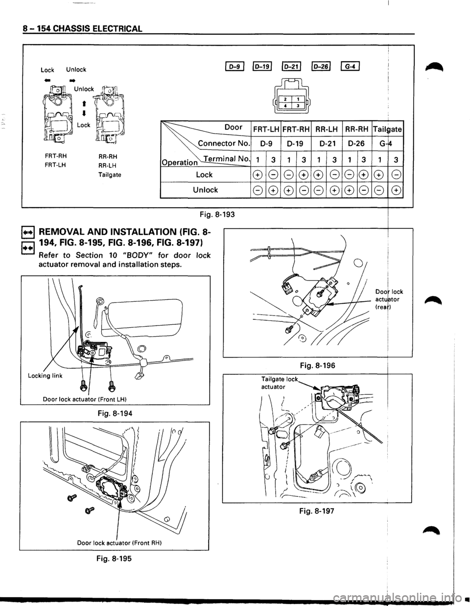
~ INSPECTION OF THE DOOR LOCK
ACTUATOR
Apply the battery voltage to the connector
terminals
of the door lock actuator to check the
operation. (Fig. 8-193)
When the
door lock actuator is checked on the
vehicle and there is no continuity, and when the
door lock actuator itself is checked and no
trouble is found, check the circuit between the
door lock actuator and the front door lock (&
power window) switch-LH for any failure.
Page 1344 of 1928
8-154 CHASSIS ELECTRICAL
Lock Unlock I D-91
Door
FRT-RH RR-RH
FRT-LH RR-LH
Tailgate Lock
Unlock
Fig. 8-193
B REMOVAL AND INSTALLATION (FIG. 8-
B 194, FIG. 8-195, FIG. 8-196, FIG. 8-197)
Refer to Section 10 "BODY" for door lock
actuator removal and installation steps.
Door lock actuator (Front LH)
Fig. 8-194
Door lock actuator (Front RH)
Fig. 8-195
lD-19l lD-21l lD-26l [E)
~
FRT-LH FRT-RH RR-LH RR-RH Tail$ate
D-9 D-19 D-21 D-26 G-
1
3 1 3 1
3 1
3 1
3
8 8 G 8
8 8
8 8 G) G
888888888 8
Fig. 8-196
Fig. 8-197
•
Page 1345 of 1928
CHASSIS ELECTRICAL 8-155
MEMO
Page 1346 of 1928
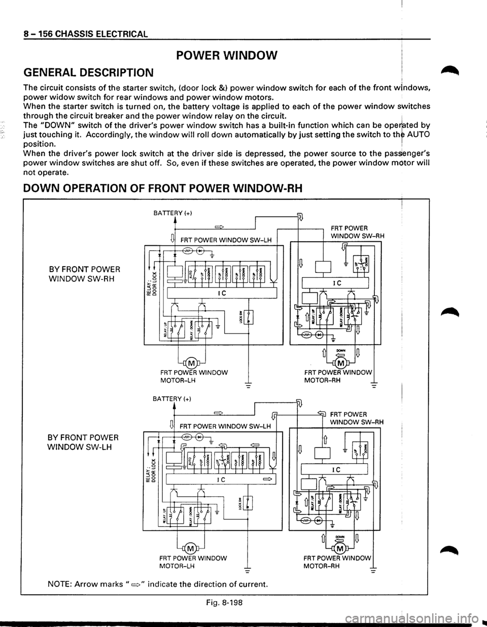
8 -156 CHASSIS ELECTRICAL
POWER WINDOW
GENERAL DESCRIPTION I
The circuit consists of the starter switch, (door lock &) power window switch for each of the front wlndows,
power widow switch for rear windows and power window motors.
When the starter switch is
turned on, the battery voltage is applied to each of the power window switches
through the circuit breaker and the power window relay on the circuit. ,
The "DOWN" switch of the driver's power window switch has a built-in function which can be ope~ted by
just.t?uching it. Accordingly, the window will roll down automatically by just setting the switch to thf AUTO
pos1t1on. ,
When the driver's power lock switch at the driver side is depressed, the power source to the pas~enger's
power window switches are shut off. So, even if these switches are operated, the power window motor will
not operate.
DOWN OPERATION OF FRONT POWER WINDOW-RH
BY FRONT POWER
WINDOW SW-RH
BATTERY(+)
D FRT POWER WINDOW SW-LH
FRT POWER WINDOW MOTOR-LH
BATTERY(+) .------'li)
FRT POWER WINDOW MOTOR-RH
1]1'------+------'"itl
BY FRONT POWER
WINDOW SW-LH
D FAT POWER WINDOW SW-LH
FAT POWER WINDOW MOTOR-LH
NOTE: Arrow marks "=>" indicate the direction of current.
Fig.
8-198
FRT POWER WINDOW MOTOR-RH
..
Page 1347 of 1928
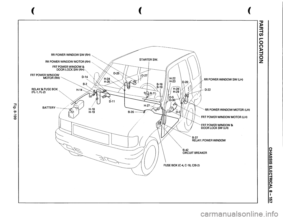
"T1 <0" 0) I ..... CD
CD
(
RR
POWER
WINDOW SW
(RH)
~
RR
POWER
WINDOW
MOTOR
(RH)
,
FRT
POWER
WINDOW
&
DOOR
LOCK
SW
(RH)
FRT
POWER
WINDOW MOTOR(RH)
RELAY
& FUSE
BOX
~
(FL-1,
FL-2)
~
BATTERY~
-,
(
"-
(
RR
POWER
WINDOW SW
(LH)
D-22 RR
POWER
WINDOW
MOTOR
(LH)
B-42
B-37
' FRT
POWER
WINDOW
MOTOR
(LH)
'FRT
POWER
WINDOW
&
DOOR
LOCK
SW
(LH)
RELAY:
POWER
WINDOW
CIRCUIT
BREAKER
~ :JJ -1 C/) r-0 0 ;; 0 2
n :X: )> 0
0 c;; m ,.. m ~ ::u c; )> ,.. co I ..,a ~
Page 1348 of 1928
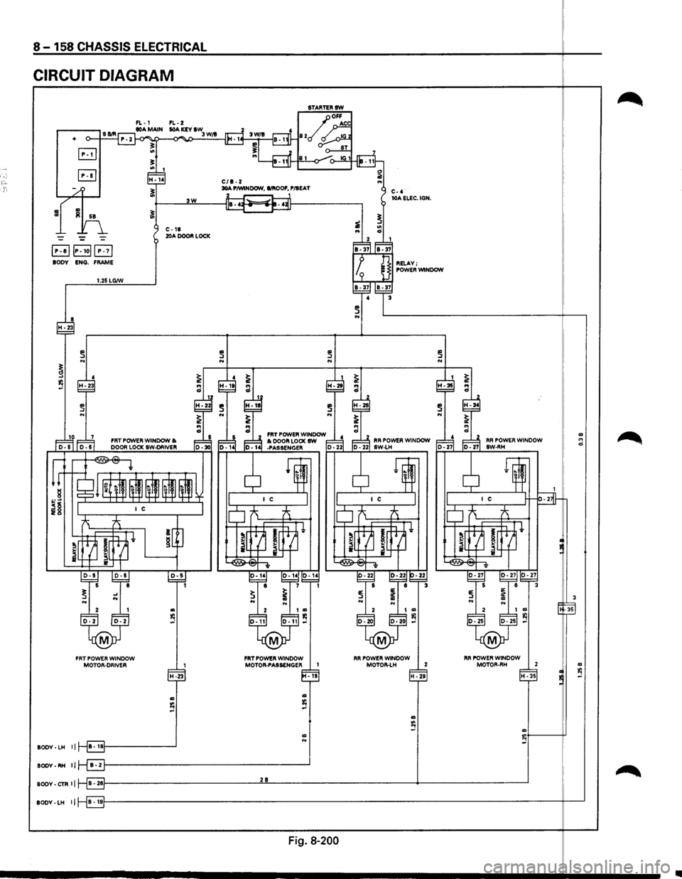
,-,·
8 -158 CHASSIS ELECTRICAL
CIRCUIT DIAGRAM
8TARTERSW
FL-1 FL-2
-II
.-----, S Bill 80A MAIN lOA KEY IW o--t---1 P. 2 ~ -<>"" 3 W/1
B .. !!:
+
"' I fP7 ~ H-14 C/1-2 1i .. ~ 30A P/WINDOW, I/IIOOF, P/IEAT
~---~3W~--~~~--------~
~
~ C-4· lOA ELEC. IGN.
"' ci i
., Iii 58
--~
E!JIP-Iol(!3 BODY ENG. FRAME
i ..
~F:d IB-37IIB-37
I p ] RELAY; I I 9 J POWER WINDOW
C-18 20A DOOR LOCK
1.25 LG/W
4 3 ~~~-37
~ N ~----------------------------~--,
~ 4 ~ I ~
~ .. .. ~
~-2~ :·It ra :·2t ~-28
a FRT POWER WINDOW ~ 1= ~ 1=~ FRT POWER WINDOW I< 1= ~ ~ I< DOOR LOCK SW d l=lJ, RR POWER WINDOW
r-'-1..;;. oor-s"'" '"'"' 1 oo,-..;;. 55.__ I_;;;.Do'"'o"'R..;;.Lo;..;CK=.;sw.;..-OR=.;IV..;;.ER'---.o;; 1oo., --~30 o-141 -PASSENGER o-221 ID -221 sw-LH
~ ~-~~~i~ II ~" ~ ~" ~
i§ I I c IO ~ ~
~ ~ •J ~~h ~r~ lrt=H•
i~~ I[ . ~~~ iL4J_ il~
... ..
2 I
D-2 D-2
M
FRT POWER WINDOW MOTOR-DRIVER
H-23
Ill
s
BODY· LH II B • IBf---------___J
~g,-~ ~g,-~~~ e 1 1
~ i N N
D-11
M
I Ill Ill D-11 ,..:
FRT POWER WINDOW MOTOR-PASSENGER I
Ill N
-19
BODY-RH II r-8f---------------------------------....l'
,-!-
.
~ 5 ~~ e r=3
~ ~ N Ill N 2 I Ill
D-20 0-20 l(l ,..:
M
FIR POWER WINDOW
MOTOII-LH 2
H
-29
I ~ H-35 .. ci
!:
:~ lM·-·~· D-27 BW-RH
~ 1~ I
I C H-s-
lo ~ -A
!~ ~ i[~t
~ v
~ s ~~~ 6 3 ~ ~ Ill .. N ~ 2 I Ill l(l D-25 D-25 ,..:
M
I RR POWER WINDOW MOTOR-RH 2
1
H -35
Ill :e ,..:
BODY-CTR II 8-261---------------------------'2'-"8'---------------------------+-------\
-----------'
Ill .. 0
3
35
Ill l(l ,..:
BODY-LH lj B • 19f---------------------------------------------------------------------\
--------it---'
Fig. 8-200
~
~
Page 1349 of 1928
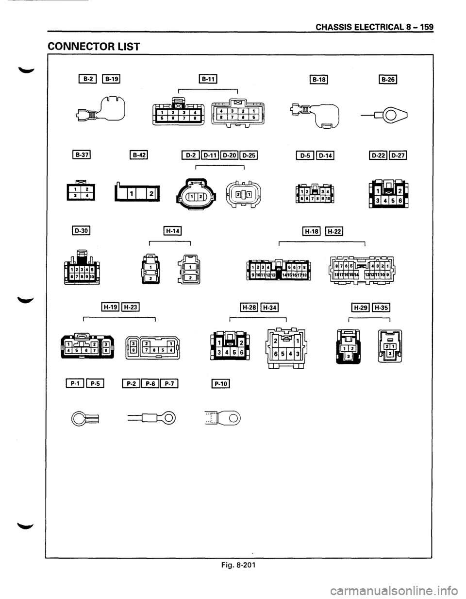
CONNECTOR LIST
Fig. 8-201
CHASSIS ELECTRICAL 8 -159
~
~
Page 1350 of 1928
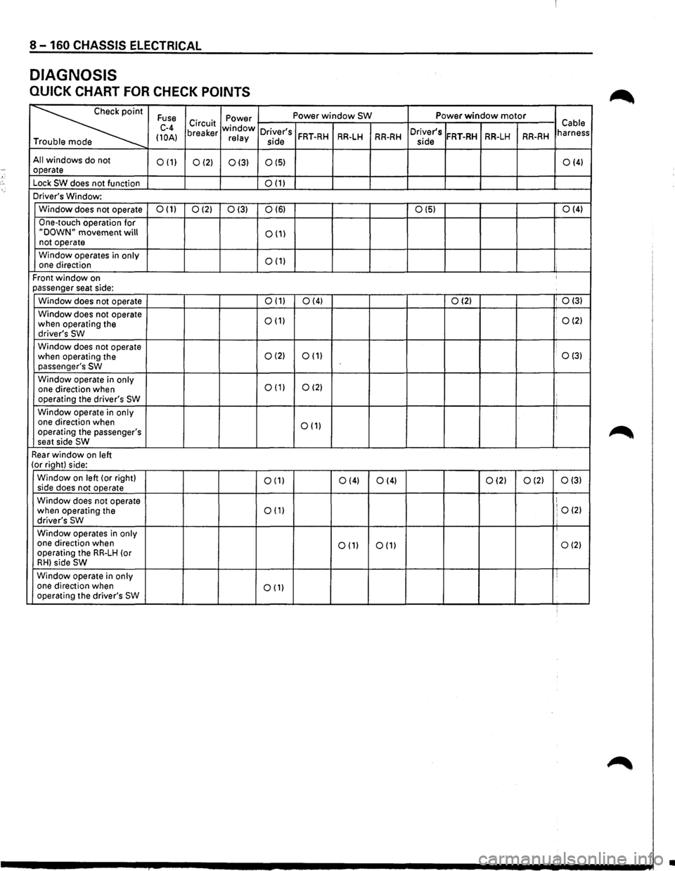
8-160 CHASSIS ELECTRICAL
DIAGNOSIS
QUICK CHART FOR CHECK POINTS
~
Fuse Power Power window SW Power window motor
C-4 Circuit window Cable
(10A) breaker relay Driver's FRT-RH RR-LH RR-RH Driver's FRT-RH RR-LH RR-RH harness
T side
side
All windows do not 0(1) 0(2) 0(3) 0(5) 0(4) operate
Lock
SW does not function 0(1)
Driver's Window:
Window does not operate
0(1) 0(2) 0(3) 0(6) 0(5) 0(4)
One-touch
operation for "DOWN" movement will 0(1) not operate
Window operates in
only 0(1) one direction
Front
window on ' passenger seat side:
Window does not operate
0(1) 0(4) 0(2) I 0(3)
Window
does not operate 0(1) . 0(2) when operating the
driver's SW
Window does not operate
when operating the 0(2) 0(1) 0(3) passenger's SW
Window operate in only 0(1) 0(2) one direction when
operating the driver's SW
Window operate in only I one direction when 0(1) operating the passenger's
seat side SW
Rear window on left (or right) side:
Window
on left (or right) 0(1) 0(4) side
does not operate 0(4) 0(2) 0(2) 0(3)
Window does not operate ! 0(2) when operating the 0(1) driver's SW ' Window operates in only one direction when
operating the RR-LH (or 0(1) 0(1) 0(2)
RH) side SW
Window
operate in only i one direction when 0(1) operating the driver's SW
•