service ISUZU TROOPER 1995 Workshop Manual
[x] Cancel search | Manufacturer: ISUZU, Model Year: 1995, Model line: TROOPER, Model: ISUZU TROOPER 1995Pages: 1928
Page 812 of 1928
6E2-116 DRIVEABILITY AND EMISSIONS
SECTION C-2
FUEL METERING SYSTEM
CONTENTS
General Description ...................... 6E2-116
Purpose ............................ 6E2-116
Modes of Operation .................... 6E2-117
Starting Mode ...................... 6E2-117
Clear Flood Mode .................... 6E2-117
RunMode ......................... 6E2-117
"Open Loop" ....................... 6E2-117
"Closed Loop" ...................... 6E2-117
Acceleration Mode ................... 6E2-117
Deceleration Mode ................... 6E2-117
Battery Positive Voltage Correction Mode ... 6E2-117
Fuel Cutoff Mode .................... 6E2-117
Fuel Metering System Components ........... 6E2-118
Fuel Supply System .................... 6E2-118
Fuel Pump Electrical Circuit ............... 6E2-118
Fuel Rail Assembly ..................... 6E2-118
Fuel Injectors ......................... 6E2-119
Fuel Injector Driver Operation ............. 6E2-119
Fuel Pressure Control Valve Assembly ....... 6E2-119
Throttle Body (TB) Assembly .............. 6E2-120
Idle Air Control (lAC) Valve .............. 6E2-120
Throttle Position (TP) Sensor ............ 6E2-121
Induction Air Control Plate System ......... 6E2-121
Diagnosis . . . . . . . . . . . . . . . . . . . . . . . . . . . . . 6E2-121
Fuel Metering System . .
. . . . . . . . . . . . . . . . 6E2-121
Fuel System Pressure Test ............... 6E2-121
Idle Air Control (lAC) Valve . .
. . . . . . . . . . . . . 6E2-121
Induction Air Control Plate System ......... 6E2-122
On-Vehicle Service ...................... 6E2-122
Fuel Pump Relay . . . . . . . . . . . . . . . . . . . . . . 6E2-122
Multipart Fuel Injection Components . . . . . . . . 6E2-122 Fuel Pressure Relief Procedure . . . . . . . . . . 6E2-122
Fuel Rail Assembly . . . . . . . . . . . . . . . . . . . . 6E2-122
Unit Repair ............................ 6E2-123
Fuel Injector/Rail ...................... 6E2-123
Throttle Body Assembly . . . . . . . . . . . . . . . . . 6E2-124
Throttle Body (TB) . . . . . . . . . . . . . . . . . . . 6E2-125
Throttle Position (TP) Sensor . . . . . . . . . . . . . 6E2-126
Idle Air Control (lAC) Valve ............... 6E2-126
Minimum Throttle Body (TB) Position Check ... 6E2-127
Chart C-2A Injector Balance ................ 6E2-128
Chart C-2C Idle Air Control (lAC) System Check .. 6E2-130
Chart C-2D Induction Air Control Plate
System Check . .
. . . . . . . . . . . . . . . . . . . . . . 6E2-132
GENERAL DESCRIPTION
PURPOSE
The function of the fuel metering system is to deliver
the correct amount of fuel to the engine under all
operating conditions. Fuel is delivered to the engine by
individual fuel injectors mounted in the intake manifold
near each cylinder.
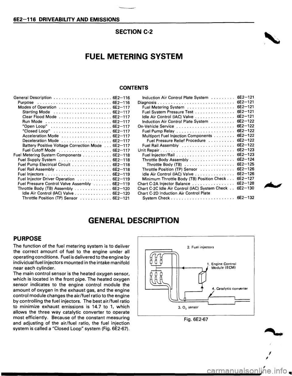
The main control sensor is the heated oxygen sensor,
which is located in the front pipe. The heated oxygen
sensor indicates
to the engine control module the
amount of oxygen in the exhaust gas, and the engine
control module changes the air/fuel ratio to the engine
by
controlling the fuel injectors. The best air/fuel ratio
to minimize exhaust emissions is 14.7 to
1, which
allows the three way catalytic converter to operate
most efficiently. Because of the constant measuring
and adjusting
of the air/fuel ratio, the fuel injection
system
is called a "Closed Loop" system (Fig. 6E2-67).
2. Fuel injectors
1. Engine Control Module (ECMl
4. Catalytic converter
3. 0, sensor
Fig. 6E2-67
I
I
Page 815 of 1928
FUEL INJECTORS
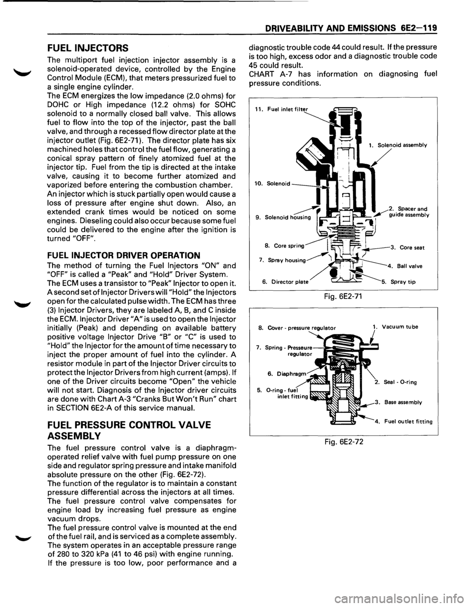
The multipart fuel injection injector assembly is a
solenoid-operated device, controlled
by the Engine
Control Module (ECM), that meters pressurized fuel to
a single engine cylinder.
The
ECM energizes the low impedance (2.0 ohms) for
DOHC or High impedance (12.2 ohms) for SOHC
solenoid to a normally closed ball valve. This allows
fuel
to flow into the top of the injector, past the ball
valve, and through a recessed
flow director plate at the
injector outlet (Fig. 6E2-71). The director plate has six
machined holes
that control the fuel flow, generating a
conical spray pattern
of finely atomized fuel at the
injector tip. Fuel
from the tip is directed at the intake
valve, causing
it to become further atomized and
vaporized before entering the combustion chamber.
An injector which is stuck partially open
would cause a
loss
of pressure after engine shut down. Also, an
extended crank times would be noticed on some
engines. Dieseling could also
occ!Jr because some fuel
could be delivered
to the engine after the ignition is
turned
"OFF".
FUEL INJECTOR DRIVER OPERATION
The method of turning the Fuel Injectors "ON" and
"OFF" is called a "Peak" and "Hold" Driver System.
The
ECM uses a transistor to "Peak" Injector to open it.
A second set
of Injector Drivers will "Hold" the Injectors
open for the calculated pulse width. The ECM has three
(3) Injector Drivers, they are labeled A, 8, and C inside
the
ECM. Injector Driver "A" is used to open the Injector
initially (Peak) and depending on available battery
positive voltage
Injector Drive "8" or "C" is used to
"Hold" the Injector for the amount of time necessary to
inject the proper amount of fuel into the cylinder. A
resistor module in part
of the Injector Driver circuits to
protect the Injector Drivers from high current (amps). If
one of the Driver circuits become "Open" the vehicle
will
not start. Diagnosis of the Injector driver circuits
are done
with Chart A-3 "Cranks But Won't Run" chart
in
SECTION 6E2-A of this service manual.
FUEL PRESSURE CONTROL VALVE
ASSEMBLY
The fuel pressure control valve is a diaphragm
operated relief valve
with fuel pump pressure on one
side and regulator spring pressure and intake manifold
absolute pressure on the other (Fig. 6E2-72).
The function
of the regulator is to maintain a constant
pressure differential across the injectors at all times.
The fuel pressure control valve compensates
for
engine load by increasing fuel pressure as engine
vacuum drops.
The fuel pressure control valve is mounted at the end
ofthe fuel rail, and is serviced as a complete assembly.
The system operates in
an acceptable pressure range
of 280 to 320 kPa (41 to 46 psi) with engine running.
If the pressure is too low, poor performance and a
DRIVEABILITV AND EMISSIONS 6E2-119
diagnostic trouble code 44 could result. If the pressure
is too high, excess odor and a diagnostic trouble code
45 could result.
CHART A-7 has information on diagnosing fuel
pressure conditions.
11. Fuel inlet
Fig. 6E2-71
1. Solenoid assembly
Spacer
and
guide assembly
. Ball valve
8. Cover-pressure regulator 1. Vacuum tube
7.
6.
Seal · 0-ring
Base assembly
Fuel
outlet fitting
Fig. 6E2-72
Page 818 of 1928
6E2-122 DRIVEABILITV AND EMISSIONS
INDUCTION AIR CONTROL PLATE
SYSTEM
Refer to CHART C-2D to diagnose the Induction air
control plate system.
ON-VEHICLE SERVICE
FUEL PUMP RELAY
The fuel pump relay is mounted in the engine
compartment.
Other than checking for loose
connectors, the only service possible is replacement.
MUL TIPORT FUEL INJECTION
COMPONENTS
WCAUTION:
VI • To reduce the risk of fire and personal injury, it
is necessary to relieve the fuel system pressure
before servicing
fuel system components.
• After relieving system pressure, a small
amount of fuel may be released when servicing
fuel lines or connections. In order to reduce the
chance
of personal injury, cover fuel line
fittings with a shop towel before disconnecting,
to catch any
fuel that may leak out. Place the
towel in an approved container when
disconnect is completed.
Fuel Pressure Relief Procedure
1. Remove fuel cap.
2. Remove fuel pump relay from underhood relay
box.
3. Start engine and allow to stall.
4. Crank engine for additional 30 seconds.
5. Remove negative battery cable.
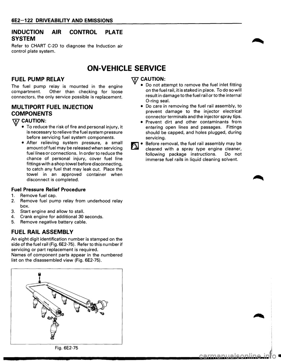
FUEL RAIL ASSEMBL V
An eight digit identification number is stamped on the
side
ofthe fuel rail (Fig. 6E2-75). Refer to this number if
servicing or part replacement is required.
Names
of component parts appear in the numbered
list on the disassembled view (Fig. 6E2-75).
'fCAUTION:
• Do not attempt to remove the fuel inlet fitting
on the
fuel rail, it is staked in place. To do so will
result
in damage to the fuel rail or to the internal
0-ring seal.
•
Do care in removing the fuel rail assembly, to
prevent damage to the injector
electrical
connector terminals and the injector spray tips.
• Prevent dirt and other contaminants from
entering open lines and passages. Fittings
should be capped, and holes plugged, during
servicing.
Before
removal, the fuel rail assembly may be
cleaned with a spray type engine cleaner,
following
package instructions. Do not
immerse fuel rails in liquid cleaning solvent.
Fig. 6E2-75
I'
---------------------'
•
Page 822 of 1928
6E2-126 DRIVEABILITV AND EMISSIONS
3. Water hoses
• Reconnect to throttle body.
2. Throttle cable and clip
1. Air duct and air cleaner upper cover
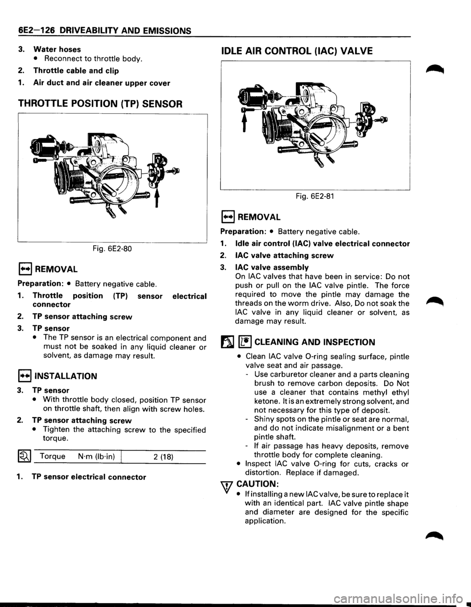
THROTTLE POSITION (TP) SENSOR
Fig. 6E2-80
1••1 REMOVAL
Preparation: • Battery negative cable.
1. Throttle position (TP) sensor electrical
connector
2. TP sensor attaching screw
3. TP sensor
• The TP sensor is an electrical component and
must not be soaked in any liquid cleaner or
solvent, as damage may result.
I••IINSTALLATION
3. TP sensor
• With throttle body closed, position TP sensor
on throttle shaft, then align
with screw holes.
2. TP sensor attaching screw
• Tighten the attaching screw to the specified
torque.
~~~ Torque N·m (lb·in) 2 (18)
1. TP sensor electrical connector
IDLE AIR CONTROL (lAC) VALVE
Fig. 6E2-81
E) REMOVAL
Preparation: • Battery negative cable.
1. Idle air control (lAC) valve electrical connector
2.
lAC valve attaching screw
3. lAC valve assembly
On lAC valves that have been in service: Do not
push or pull on the lAC valve pintle. The force
required
to move the pintle may damage the
threads on the
worm drive. Also, Do not soak the
lAC valve in any liquid cleaner or solvent, as
damage may result.
f}J [1!) CLEANING AND INSPECTION
• Clean lAC valve 0-ring sealing surface, pintle
valve seat and air passage.
- Use carburetor cleaner and a parts cleaning
brush
to remove carbon deposits. Do Not
use a cleaner
that contains methyl ethyl
ketone.
It is an extremely strong solvent, and
not necessary for this type of deposit.
-
Shiny spots on the pintle or seat are normal,
and
do not indicate misalignment or a bent
pintle shaft.
-
If air passage has heavy deposits, remove
throttle
body for complete cleaning.
• Inspect lAC valve 0-ring for cuts, cracks or
distortion. Replace
if damaged.
WCAUTION:
VI • If installing a new lAC valve, be sure to replace it
with an identical part. lAC valve pintle shape
and diameter are designed
for the specific
application.
Page 824 of 1928
6E2-128 DRIVEABILITY AND EMISSIONS
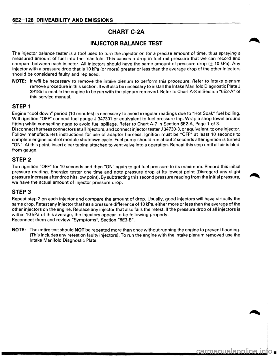
CHART C-2A
INJECTOR BALANCE TEST
The injector balance tester is a tool used to turn the injector on for a precise amount of time, thus spraying a
measured
amount of fuel into the manifold. This causes a drop in fuel rail pressure that we can record and
compare between each injector.
All injectors should have the same amount of pressure drop (± 10 kPa). Any
injector with a pressure drop that is 10 kPa (or more) greater or less than the average drop of the other injectors
should be considered faulty and replaced.
NOTE: It will be necessary to remove the intake plenum to perform this procedure. Refer to intake plenum
remove procedure in this section. It will also be necessary to install the Intake Manifold Diagnostic Plate J
39185 to enable the engine to be run with the plenum removed. Refer to Chart A-8 in Section "6E2-A" of
this service manual.
STEP 1
Engine "cool down" period (10 minutes) is necessary to avoid irregular readings due to "Hot Soak" fuel boiling.
With ignition "OFF" connect fuel gauge J 347301 or equivalent to fuel pressure tap. Wrap a shop towel around
fitting
while connecting gage to avoid fuel spillage. Refer to Chart A-7 in Section 6E2-A, Page 1 of 3.
Disconnect harness connectors at all injectors, and connect injector tester J 34730-3, or equivalent, to one injector.
Follow manufacturers instructions for use of adaptor harness. Ignition must be "OFF" at least 10 seconds to
complete engine control module shutdown cycle. Fuel pump should run about 2 seconds after ignition is turned
"ON". At this point, insert clear tubing attached to vent valve into a operation. Repeat this step until all air is bled
from gauge.
STEP 2
Turn ignition "OFF" for 10 seconds and then "ON" again to get fuel pressure to its maximum. Record this initial
pressure reading. Energize tester one time and note pressure drop at its lowest point (Disregard any slight
pressure increase after drop hits low point). By subtracting this second pressure reading from the initial pressure, ~
we have the actual amount of injector pressure drop.
STEP 3
Repeat step 2 on each injector and compare the amount of drop. Usually, good injectors will have virtually the
same drop. Retest any injector
that has a pressure difference of 10 kPa, either more or less than the average of the
other injectors on the engine.
Replace any injector that also fails the retest. If the pressure drop of all injectors is
within 10 kPa of this average, the injectors appear to be following properly.
Reconnect them and review "Symptoms", Section "6E3-B".
NOTE: The entire test should NOT be repeated more than once without running the engine to prevent flooding.
(This includes any retest on faulty injectors). To run the engine with the intake plenum removed use the
Intake Manifold Diagnostic Plate.
•
Page 830 of 1928
6E2-134 DRIVEABILITV AND EMISSIONS
SECTION C-3
EVAPORATIVE EMISSION (EVAP) CONTROL SYSTEM
(ELECTRONICALL V CONTROLLED)
CONTENTS
General Description ...................... 6E2-134
Purpose ............................ 6E2-134
Vapor Canister ........................ 6E2-134
Evaporative Emission (EVAP) Control System .. 6E2-134 Results of Incorrect Operation ............. 6E2-135
Diagnosis ............................. 6E2-135
Visual Check of Canister ................. 6E2-135
On-Vehicle service . . . . . . . . . . . . . . . . . . . . . . 6E2-135
Fuel Vapor Canister . . . . . . . . . . . . . . . . . . . . 6E2-135
Canister Hoses . . . . . . . . . . . . . . . . . . . . . . . 6E2-135
Chart C-3 Evaporate Emission Canister
Purge Valve . . . . . . . . . . . . . . . . . . . . . . . . . 6E2-136
GENERAL DESCRIPTION
PURPOSE
The basic Evaporative Emission (EVAP) Control
System used on
all vehicles is the charcoal canister
storage method. This method transfers fuel
vapor
from the fuel tank to an activated carbon (charcoal)
storage device (canister)
to hold the vapors when the
vehicle
is not operating. When the engine is running,
the fuel
vapor is purged from the carbon element by
intake air flow and consumed in the normal
combustion process.
VAPOR CANISTER
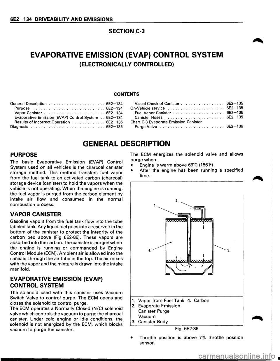
Gasoline vapors from the fuel tank flow into the tube
labeled tank.
Any liquid fuel goes into a reservoir in the
bottom of the canister to protect the integrity of the
carbon bed above (Fig 6E2-86). These vapors are
absorbed into the carbon. The canister is purged
when
the engine is running or commanded by Engine
Control Module (ECM).
Ambient air is allowed into the
canister through the air tube in the top. The air mixes
with the vapor and the mixture is drawn into the intake
manifold.
EVAPORATIVE EMISSION (EVAP)
CONTROL SYSTEM
The solenoid used with this canister uses Vacuum
Switch Valve to control purge. The ECM opens and
closes the solenoid to control purge.
The
ECM operates a Normally Closed (N/C) solenoid
valve
which controls the vacuum to purge the charcoal
canister. Under cold engine
or idle conditions, the
solenoid is
not energized by the ECM, which blocks
vacuum
to purge the canister. The
ECM energizes
the solenoid valve and allows
purge when:
• Engine is warm above sg·c (156.F).
• After the engine has been running a specified
time.
4.
1. Vapor from Fuel Tank 4. Carbon
2. Evaporate Emission
Canister Purge
Vacuum
3. Canister Body
Fig. 6E2-86
3.
• Throttle position is above 7% throttle position
sensor.
•
Page 831 of 1928
RESULTS OF INCORRECT OPERATION
Poor idle, stalling and poor driveability can be caused
by:
• Inoperative purge solenoid.
•
Damaged canister.
• Hoses split, cracked and/or not connected to the
proper tubes.
Evidence
of fuel loss or fuel vapor odor can be caused
by:
• Liquid fuel leaking from fuel lines, or fuel pump.
DRIVEABILITY AND EMISSIONS 6E2-135
• Cracked or damaged canister.
• Disconnected, misrouted, kinked, deteriorated or
damaged vapor hoses,
or control hoses.
If the solenoid is always open, the canister can purge to
the intake manifold at all times. This can allow extra
fuel at idle or during warm-up, which can cause rough
or unstable idle, or too rich operation.
If the solenoid is always closed, the canister can
become over-loaded,
resulting in fuel odor.
DIAGNOSIS
The evaporate em1ss1on canister purge solenoid
operation is covered in CHART C-3 at the end of this
section. VISUAL CHECK OF CANISTER
Cracked or damaged, replace canister.
FUEL VAPOR CANISTER
1••1 Remove or Disconnect
ON-VEHICLE SERVICE
CANISTER HOSES
1. Hoses from canister. Mark hoses to install on new
canister. Refer
to Vehicle Emission Control
Information label for
routing of canister hoses. When replacing hoses, use
6148M
or its equivalent.
2. Canister.
l••llnstall or Connect
1. Canister as removed.
2. Hoses. Make sure connetions are correct.
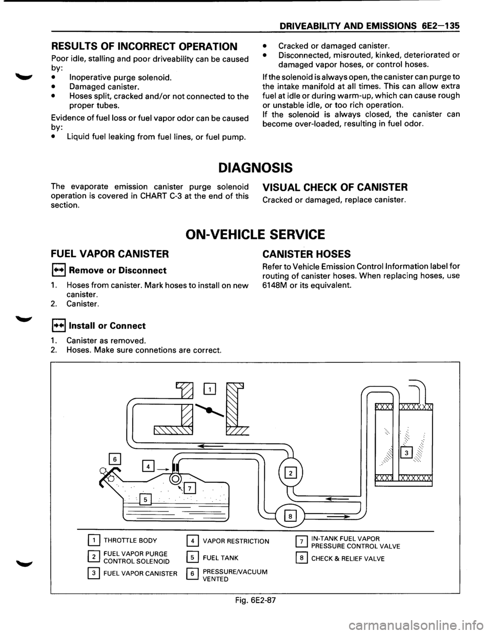
[2] THROTTLE BODY
r:l FUEL VAPOR PURGE ~ CONTROL SOLENOID
0 FUEL VAPOR CANISTER
0 VAPOR RESTRICTION
0 FUEL TANK
r.;;'l PRESSURENACUUM L....J VENTED
Fig. 6E2-87
r-:;-1 IN-TANK FUEL VAPOR ~ PRESSURE CONTROL VALVE
0 CHECK & RELIEF VALVE
Page 834 of 1928
6E2-138 DRIVEABILITY AND EMISSIONS
SECTION C4
ELECTRONIC IGNITION (EI) SYSTEM/IGNITION CONTROL (IC)
CONTENTS
General Description . . . . . . . . . . . . . . . . . . . . . 6E2-138
Purpose
............................ 6E2-138
Operation
........................... 6E2-138
Results of Incorrect Operation . . . . . . . . . . . 6E2-139
How diagnostic trouble code (DTC) 42 is
Determined ........................ 6E2-139
Diagnosis. . . . . . . . . . . . . . . ............. 6E2-139
Diagnostic
trouble code (DTC) 12 . . . . . . . . . 6E2-139
On-Vechicle Service . .
. . . . . . . . . . . . . . . . . . . 6E2-139
Electronic Ignition (EI) Assembly .......... 6E2-139
Crankshaft Position (CKP) Sensor ......... 6E2-140
Ignition Coil
.......................... 6E2-140
Ignition Control
Module (ICM) ............ 6E2-140
Ignition
Timing ....................... 6E2-140
Chart
C-4D-1 Electronic Ignition (EI) misfire
at
Idle .............................. 6E2-142
Chart C-4D-2 Electronic Ignition (EI) misfire
Under Load .......................... 6E2-144
GENERAL DESCRIPTION
PURPOSE
The Electronic Ignition (EI) system controls fuel
combustion by providing a spark to ignite the
compressed
air/fuel mixture at the correct time. To
provide improved engine performance,
fuel economy,
and
control of exhaust emissions, the Engine Control
Module
(ECM) controls spark advance timing with the
Ignition Control (IC) system.
OPERATION
The "EI" is a "waste spark" system in which 2 plugs are
fired
simultaneously from one coil. The spark plugs are
paired
to a coil, so that when both fire, one cylinder is
on the compression stroke and the other is on exhaust.
There is
Iitie resistance across the plug gap on the
exhaust stroke, so the
plug requires very little voltage
to fire, thereby providing the other plug (compression)
with maximum available voltage.
The system uses a magnetic Crankshaft Position (CKP)
sensor which protrudes into the block, within
approximately .050" of the crankshaft reluctor. The
reluctor is a special wheel cast on the crankshaft that
has seven machined
slots, six of which are equally
spaced 60° apart). The seventh slot is spaced 1 oo from
one
of the other slots. As the reluctor rotates with the
crankshaft, the
slots change the magnetic field of the
sensor, causing
an induced voltage pulse.
By counting the time between pulses, the Ignition
Control Module (ICM)
can recognize the pulse of the
seventh
slot (sync pulse). Based on this sync pulse, the
module sends the reference signal to the ECM to
calculate CKP (used to fire coils in correct sequence)
and engine speed.
To
properly control timing, the ECM relies on the
following information:
• Engine load (manifold absolute pressure or
vacuum).
• Atmospheric (barometric) pressure.
• Engine temperature.
• Intake air temperature.
• CKP
• Engine speed (revolution per minute).
The ignition
control system consisits of the "EI"
assembly (coils, module,
and CKP sensor), ECM and
connecting wires. These circuits
perform the following
functions:
• "EI" reference
The CKP sensor sends a signal to the ICM which
generates a reference
pulse which is sent to the
ECM. The ECM uses this signal to calculate CKP
and engine speed (also used to trigger the
injector).
• Reference ground (GND)
This wire is GNd through the module and makes
sure the GNd circuit has no
voltage drop between
the
ICM and the ECM, which if open, could affect
performance.
• Bypass
At about 400 revolution per minute, the ECM
applies 5 volts to this circuit to switch spark timing
control from the ICM to the ECM. An open or
grounded bypass circuit
will set a diagnostic
trouble code 42 and the engine will run at base
timing,
plus a small amount of advance built into
the
ICM.
• IGNITION CONTROL (IC)
The ECM uses this circuit (when bypass voltage is
applied) to trigger the "EI" module. The ECM uses
the
CKP to base its calculation of the amount of
spark advance needed under present engine
conditions.
•
Page 835 of 1928
RESULTS OF INCORRECT OPERATION
An open or ground in the Ignition Control (I C) or bypass
circuits
will set a Diagnostic Trouble Code (DTC) 42 and
cause the engine
to run on the Ignition Control Module
(ICM)
timing.
The Engine
Control Module (ECM) uses information
from the Intake Air Temperature (IAT) and engine
coolant sensors in addition to revolution per minute
(rpm) to
calculate spark advance as follows:
• Cold
engine -more spark advance.
• Engine under minimum load based on rpm and
low amount of air flow = more spark advance.
• Hot engine = less spark advance.
• Engine under heavy load based on rpm and high
air
flow = less spark advance.
HOW DIAGNOSTIC TROUBLE CODE (DTC)
42 IS DETERMINED
When the system is running on the ICM, that is, no
voltage on the bypass line, the ICM grounds (GND) the
IC signal. The ECM expects to see no voltage on the IC
line during this condition.lf it sees a voltage, it sets DTC
42 and will not go into the IC mode.
DRIVEABILITY AND EMISSIONS 6E2-139
When the rpm for IC is reached (about 400 rpm) the
ECM applies 5 volts to the bypass line and the IC should
no longer be grounded in the ICM so the IC voltage
should
be varying.
An open in the
IC circuit while running, will result in the
engine continuing to run, but in a back-up
ig~it~on
timing mode (module timing) at a calculated t1mmg
value
and the malfunction indicator lamp will not be
"ON".
If
the IC circuit is shorted to GND, the "Check Engine"
malfunction
indicator lamp will be turned "ON", and a
DTC 42 will be set and the engine will operate in
module timing. Either condition may cause poor
performance and reduced
fuel economy.
If the bypass line is open or GND, the ICM will not
switch to IC mode so the IC voltage will be low and DTC
42 will be set.
If the IC line is grounded, the ICM will switch to IC, but
because the line isGNDtherewill be no ICsignai.A DTC
42 will be set.
DIAGNOSIS
If the engine cranks but will not run, CHART A-3 will be
used to determine if the Electronic Ignition (EI) system
is the cause
of the problem or if it is another part of the
fuel injection system.
If DTC 42 is set, that DTC chart should be used for
diagnosis. If no DTC is set and the ignition system is
suspected, use
CHART C4-D ("EI" Misfire) for
diagnosis.
DIAGNOSTIC TROUBLE CODE (DTC) 12
DTC 12 is used during the on-board diagnostic system
check procedure to test the
DTC display ability of the
ECM. This diagnostic trouble code indicates that the
ECM is not receiving the engine speed (REFERENCE)
signal. This occurs with the ignition key "ON" and the
engine not running.
The "reference"
signal also triggers the fuel injection
system.
Without the "reference" signal the engine
cannot run.
ON-VEHICLE SERVICE
ELECTRONIC IGNITION (EI) ASSEMBLY
1••1 REMOVE OR DISCONNECT
1. Negative battery cable
2. "EI" electrical connectors (3)
3. Spark plug wires. (Note wire positions to proper
coils) (6)
4. "EI" assembly to bracket bolts (3)
5. "EI" assembly from Intake Plenum.
1••1 INSTALL OR CONNECT
1. "EI" assembly bracket to Intake Plenum
Tighten bolts to 25 N·m (19 lb·ft)
2. Spark plug wires to correct spark plugs
3. "EI" electrical connectors
4. Negative battery cable
Page 842 of 1928
6E2-146 DRIVEABILITY AND EMISSIONS
SECTION C-5
KNOCK SENSOR (KS) SYSTEM
(DOHC ONLY)
CONTENTS
General Description ..................... 6E2-146 On-Vehicle Service ...................... 6E2-147
Purpose
............................ 6E2-146 Knock Sensor (KS) System ............... 6E2-147
Operation . . . . . . . . . . . . . . . . . . . . . . . . . . . 6E2-146 Knock
Sensor
(KS) Module .............. 6E2-147
Diagnosis
............................. 6E2-146 Chart C-5 Knock Sensor (KS) System Check ... 6E2-148
Results
Of Incorrect Knock Sensor (KS)
System Operation .................... 6E2-146
GENERAL DESCRIPTION
PURPOSE
To control spark knock, a Knock Sensor (KS) system
has been added. This system is designed to retard
spark timing up to
20·, to reduce spark knock in the
engine. This
allows the engine to use maximum spark
advance to improve driveability and fuel economy.
Varying octane
levels in gasoline can cause detonation
in engines. Detonation
is called spark knock.
OPERATION
The KS system has two major components:
• KS Module
• KS System
The sensor is mounted in the engine block under the
Intake Manifold assembly. When the KS detects
abnormal vibration (spark knocking) in the engine,
it
produced a voltage that is received by the KS module.
As long
as the KS module sees no voltage from the KS
(knock not present), it sends a signal voltage (8 to 10
volts) to the Engine Control Module (ECM) and the ECM
provides normal spark advance.
When the module detects voltage
from the KS (knock
present),
it turns "OFF" the signal to the ECM and the
voltage at terminal
"D1 0" goes toO volts. The ECM then
retards ignition control
(IC) to reduce spark knock.
The
KS signal line has a shield wire to prevent any false
signals to the
KS module. If the shield wire loses it
ground a false diagnostic trouble code (DTC) 43 may
result
or the ignition timing maybe retard needlessly.
DIAGNOSIS
RESULTS OF INCORRECT KNOCK SENSOR
(KS) SYSTEM OPERATION
Loss of the KS signal or loss of ground at KS module
would cause the signal to the ECM to remain high. This
condition
would cause the ECM to control IC, as if no
spark knocking were happening. No retard
would
occur, and spark knocking could become severe under
heavy engine load conditions. Loss
of the KS signal
to the ECM would cause the ECM
to constantly retard IC. This could result in sluggish
performance and cause a
DTC 43 to set.
A
"Scan tool" will read KC signal in A/D counts. When
detonation is detected,
KC signal counts will
increment, as long as knock is present. "Scan tools"
will
indicate knock being present either by showing
AID counts, or displaying "Yes" (knock present), or
"No" (knock not present). If DTC 43 is present, use that
chart to diagnose system. If no DTC is present and KS
system is suspected, use CHART C-5.
•