ISUZU TROOPER 1995 Workshop Manual
Manufacturer: ISUZU, Model Year: 1995, Model line: TROOPER, Model: ISUZU TROOPER 1995Pages: 1928
Page 1561 of 1928
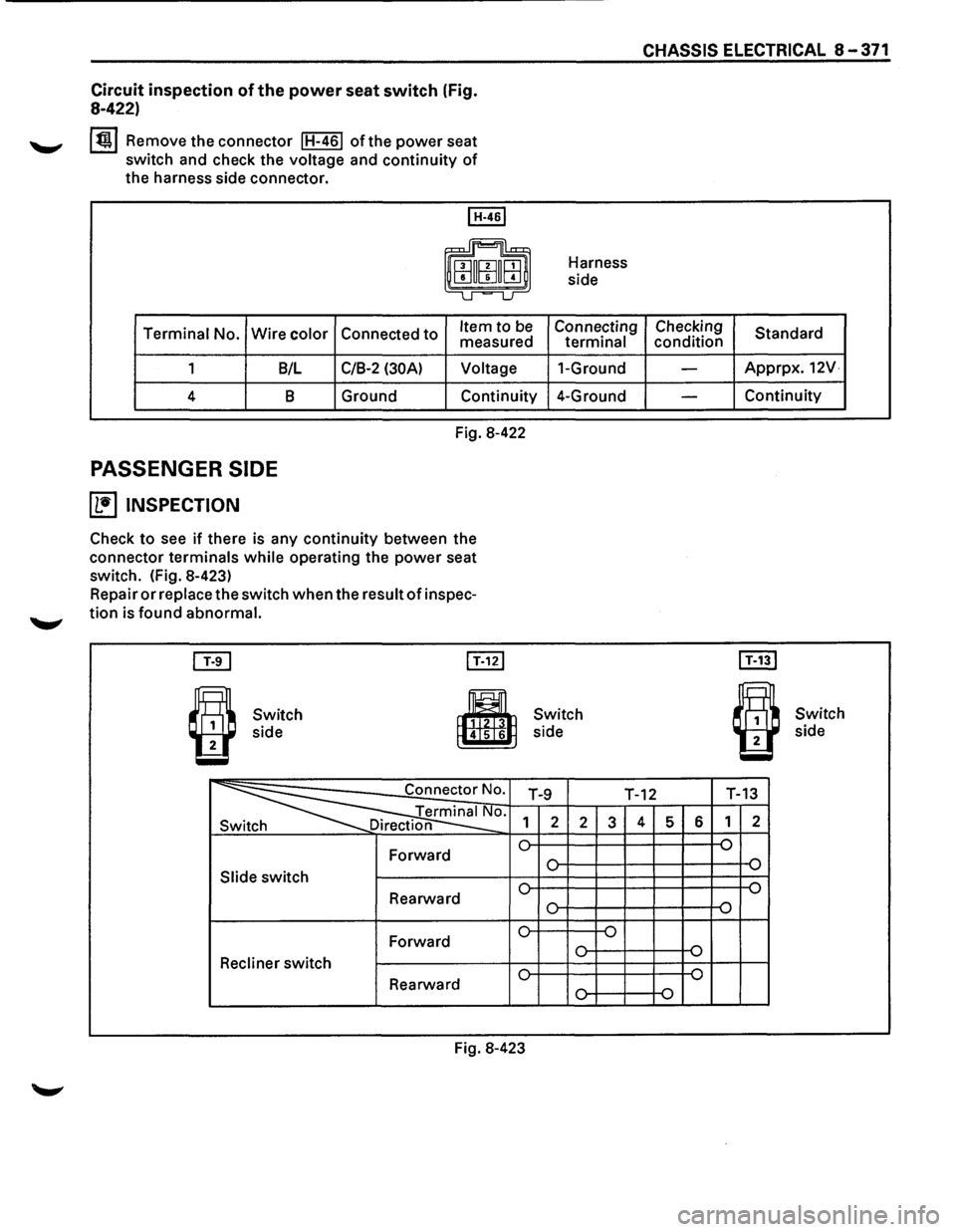
Circuit inspection of the power seat switch (Fig.
8-422)
lti!.l Remove the connector IH-461 ofthe power seat
switch and check the
voltage and continuity of
the harness side connector.
I H-461
a u~u
Terminal No. Wire color Connected to Item to be
measured
1 8/L C/8-2
(30A)
Voltage
CHASSIS ELECTRICAL 8-371
Harness
side
Connecting Checking
Standard
terminal condition
1-Ground
-Apprpx. 12V·
4 8 Ground Continuity 4-Ground -Continuity
PASSENGER SIDE
(1!] INSPECTION
Fig. 8-422
Check
to see if there is any continuity between the
connector
terminals while operating the power seat
switch. (Fig. 8-423)
Repair
or replace the switch when the result of inspec
tion is found abnormal.
[ill I T-121
I
Switch
a side Switch
side
~0. T-9
Terminal No. 1 2
2
Sw Direction
0 Forward
Slide switch 0
0
Rearward 0
0 Forward 0 Recliner switch 0 Rearward 0
Fig. 8-423
I T-131
I
Switch
side
T-12 T-13
3 4
5 6
1 2
-o
{)
{)
"' ....,
-o
"' ....,
{)
-o
Page 1562 of 1928
8-372 CHASSIS ELECTRICAL
Circuit
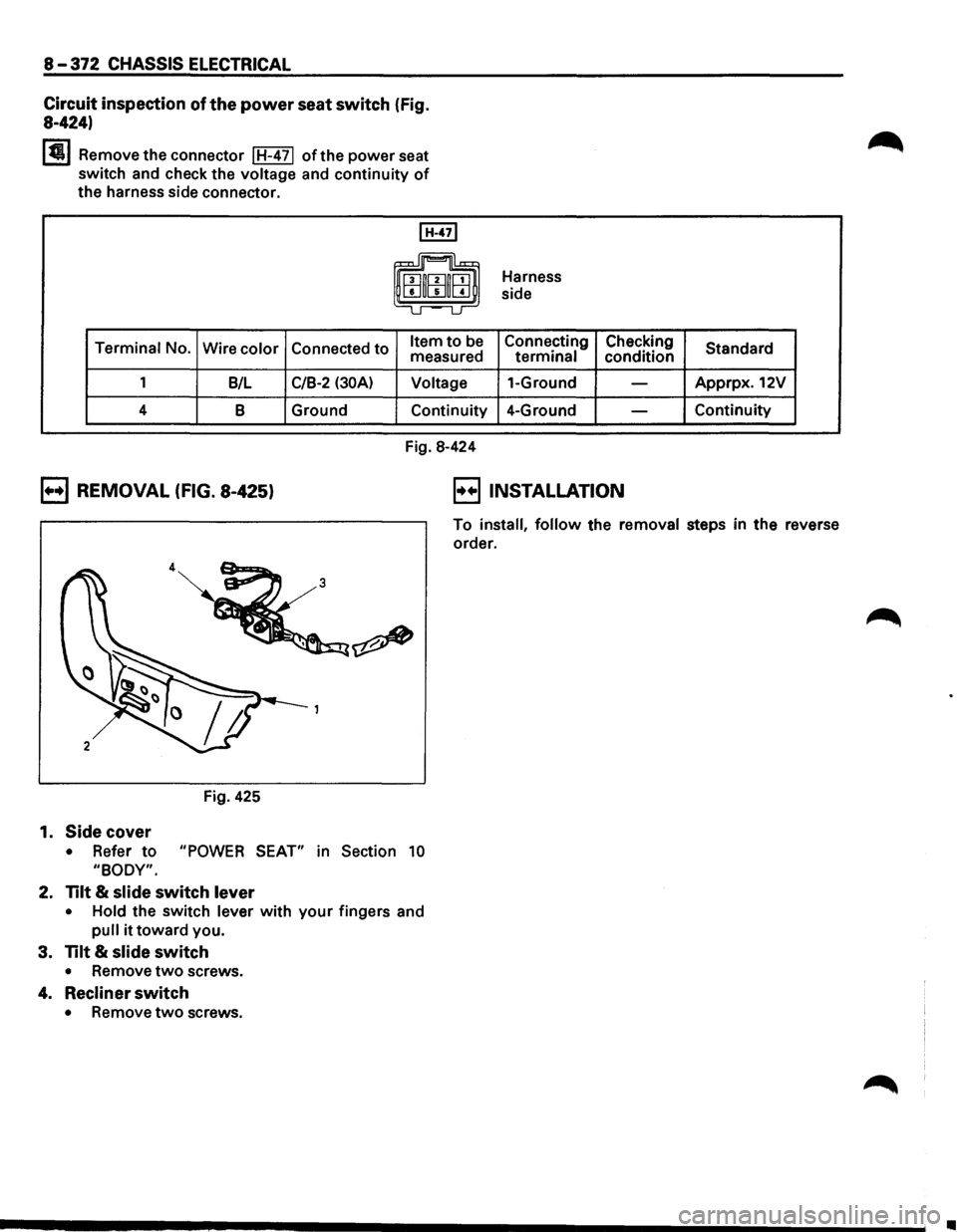
inspection of the power seat switch (Fig.
8-424)
I~ I Remove the connector I H-4 71 of the power seat
switch and check the voltage and continuity
of
the harness side connector.
I H-471
0 ~u
Terminal No.
Wire color Connected to Item to be measured
1 B/L
C/B-2 (30A) Voltage
4 B Ground
Continuity
Fig.
8-424 Harness
side
Connecting Checking
terminal condition
1-Ground
-
4-Ground -
B REMOVAL (FIG. 8-425) B INSTALLATION
Standard
Apprpx. 12V
Continuity
To
install, follow the removal steps in the reverse
order.
Fig.
425
1. Side cover
• Refer to "POWER SEAT" in Section 10
"BODY".
2. Tilt & slide switch lever
• Hold the switch lever with your fingers and
pull it toward you.
3. Tilt & slide switch
• Remove two screws.
4. Recliner switch
• Remove two screws.
Ill
Page 1563 of 1928
FRONT TILT MOTOR
REAR TILT MOTOR
~ SLIDE MOTOR
RECLINER MOTOR
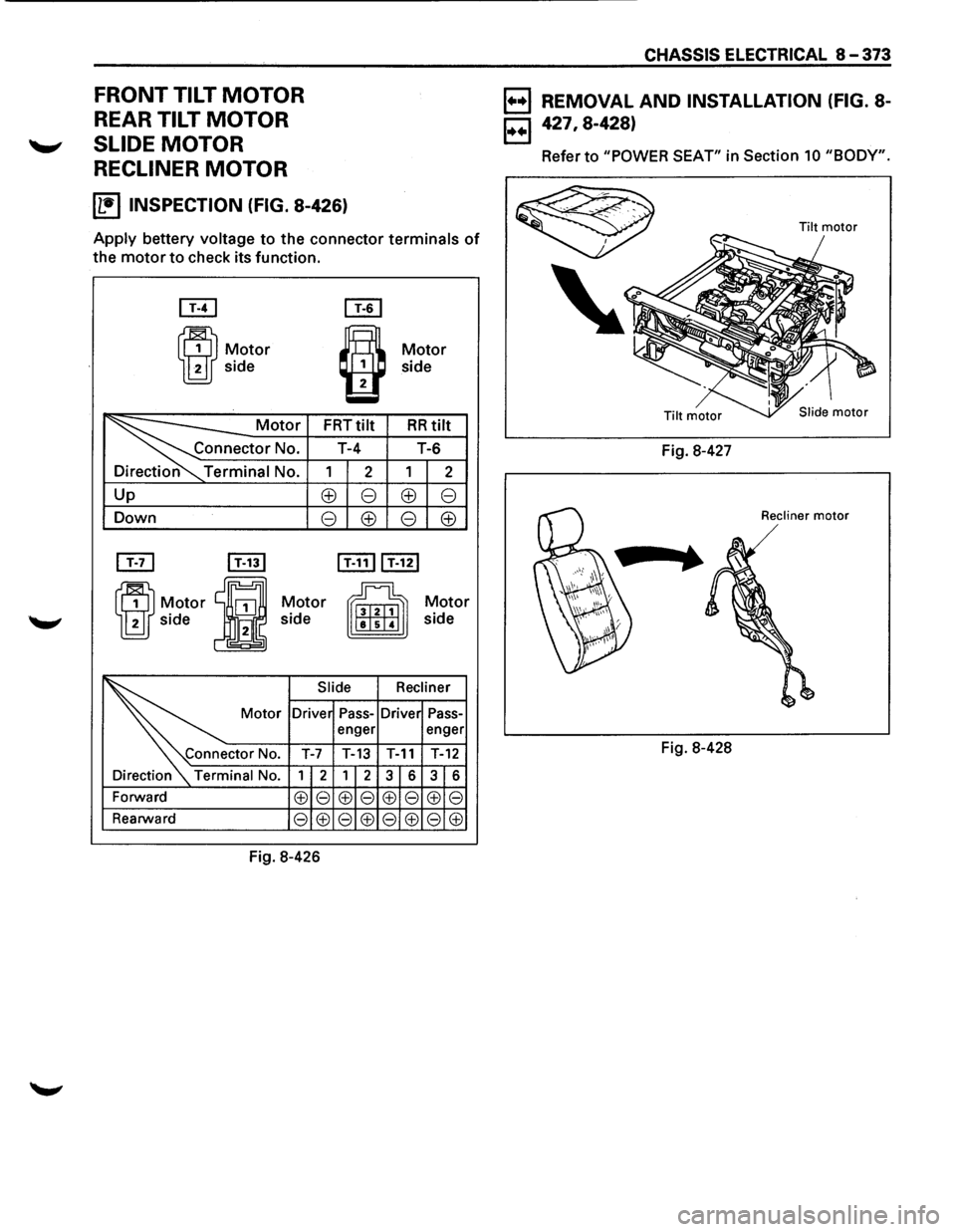
~ INSPECTION (FIG. 8-426)
Apply bettery voltage to the connector terminals of
the motor to check its function.
[BJ
ffl ~otor
10J s1de
Motor
side
~ Motor FRT tilt RRtilt
Connector No.
T-4 T-6
Terminal No. 1 2 1 2
Up
Down
Direction
Forward
Rearward
8:>
8
Motor
side
8 8:> 8
8:> 8 8:>
I T-1111 T-121
~ Motor
gj side
Slide Recliner
Motor Drivel Pass-Driver Pass-
enger enger
Connector No.
T-7 T-13 T-11 T-12
Terminal No. 1 2 1 2
3 6 3 6
8:) 8 8:) 8 8:) 8 8:) 8
8
8:) 8 8:) 8 8:) 8 8:)
Fig. 8-426
CHASSIS ELECTRICAL 8-373
l••l REMOVAL AND INSTALLATION (FIG. 8-
B 427. 8-428)
Refer to "POWER SEAT" in Section 10 "BODY".
Tilt motor
Fig. 8-427
Recliner motor
Fig. 8-428
Page 1564 of 1928
8-374 CHASSIS ELECTRICAL
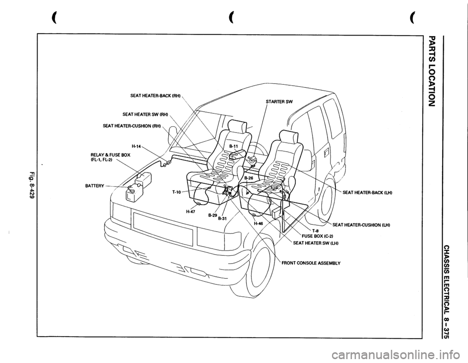
SEAT HEATER
GENERAL DESCRIPTION
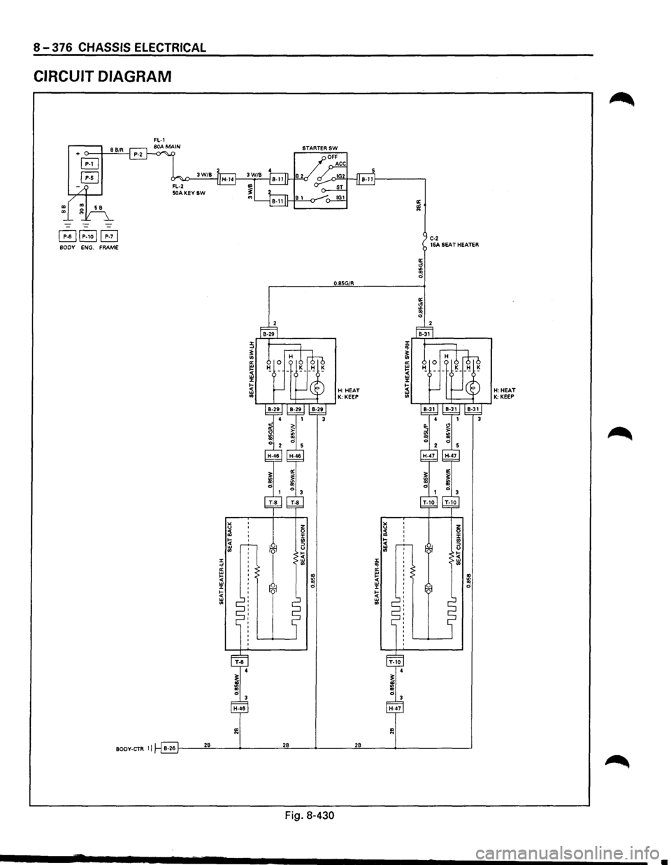
The circuit consists of the starter switch, seat heater switch and the heat unit.
The seat heater is provided in driver's and front passenger seats
(as option). When the seat heater switch is
ON, the seat heater built in the seat back and cushion is switched on to warm the seats.
To prevent the seats
from being overheated, the circuit is fitted with a thermostat.
Ill
Page 1565 of 1928
, cE" 00 I ~ ~
SEAT
HEATER·BACK
IRHI,
',
SEAT
HEATER
SW
IRHI
"·
SEAT
HEATER-CUSHION
(RHI
RELAY
& FUSE
BOX
IFL-1,
FL-21
H-14
BATTERY
/ '
#..
(
(
SEAT
HEATER-BACK
ILHI
SEAT
HEATER-CUSHION
(lH)
SEAT
HEATER
SW
ILHI
FRONT
CONSOLE
ASSEMBLY
~ ~ r-0 0 ~ -0 2
n ::t 1: (/) c;; m rm ~ ::D 0 )> r-01) I w ..... C1l
Page 1566 of 1928
8-376 CHASSIS ELECTRICAL
CIRCUIT DIAGRAM
+ o---i--.!8'-!B~/R-'---j
~~P-1ojEj C-2 BODY ENG. FRAME 15A SEAT HEATER
O.BSG/R
BODY-CTR II B-26 1----'2"'8------------"2"-8--~._ ___ __,2-"8---~.._ _______ __,
Fig. 8-430
•
Page 1567 of 1928
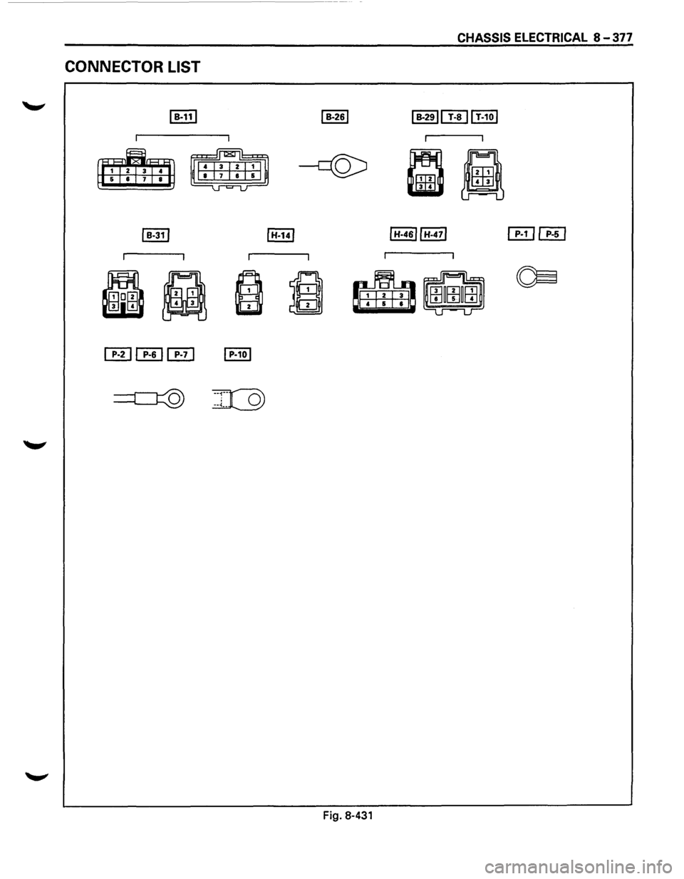
CONNECTOR LIST
~
~
CHASSIS ELECTRICAL 8 -377
Fig. 8-431
Page 1568 of 1928
8-378 CHASSIS ELECTRICAL
DIAGNOSIS
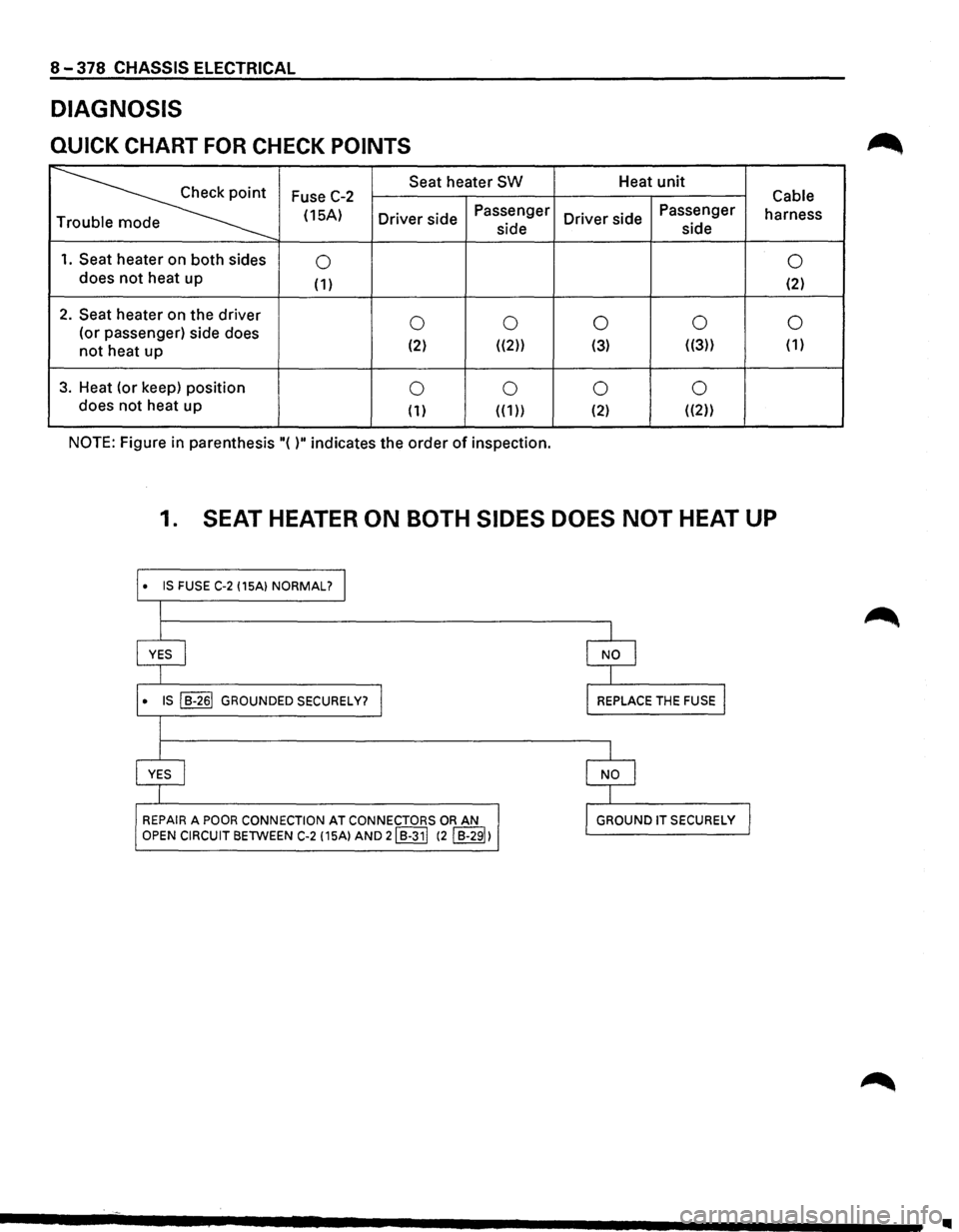
QUICK CHART FOR CHECK POINTS
~
Seat heater SW Heat unit Fuse C-2 Cable
(15A)
Driver side Passenger
Driver side Passenger
harness
e side side
1. Seat heater
on both sides 0 0 does not heat
up (1) (2)
2. Seat heater on the driver 0 0 0 0 0 (or
passenger) side does
not heat up (2) ((2)) (3) ((3))
( 1)
3. Heat (or keep) position 0 0 0 0 does
not heat up
( 1) ( ( 1)) (2) ((2))
NOTE: Figure in parenthesis "( )" indicates the order of inspection.
1. SEAT HEATER ON BOTH SIDES DOES NOT HEAT UP
• IS FUSE C-2 (15A) NORMAL? I
I
I
YES I
l
• IS ~ GROUNDED SECURELY? I
l
l
YES I
I
REPAIR A POOR CONNECTION AT CONNECTORS OR AN
OPEN CIRCUIT BETWEEN C-2 (15A) AND 21 B-311 (2 I B-291)
I
I NO I
I
l REPLACE THE FUSE I
I
I NO I
I
l GROUND IT SECURELY J
Page 1569 of 1928
CHASSIS ELECTRICAL 8-379
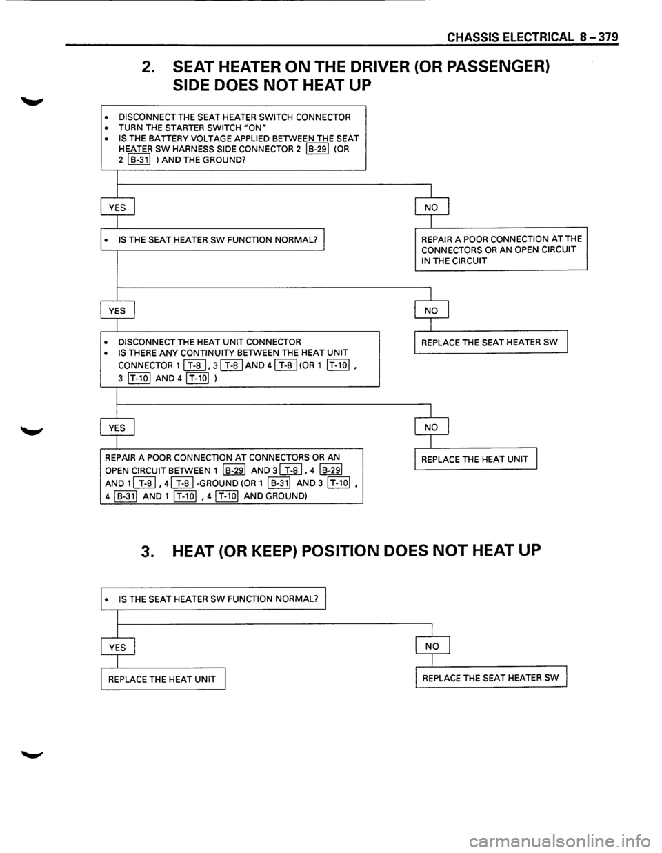
2. SEAT HEATER ON THE DRIVER (OR PASSENGER)
SIDE DOES NOT HEAT UP
• DISCONNECT THE SEAT HEATER SWITCH CONNECTOR
• TURN THE STARTER SWITCH uoN"
• IS THE BATTERY VOLTAGE APPLIED BETWEEN THE SEAT HEATER SW HARNESS SIDE CONNECTOR 2 IB-291 (OR
2 I B-311 ) AND THE GROUND?
I
YES
I NO I
1
• IS THE SEAT HEATER sw FUNCTION NORMAL? I REPAIR A POOR CONNECTION AT THE CONNECTORS OR AN OPEN CIRCUIT
IN
THE CIRCUIT
I
YES
I NO l
I
• DISCONNECT THE HEAT UNIT CONNECTOR REPLACE THE SEAT HEATER SW I
• IS THERE ANY CONTINUITY BETWEEN THE HEAT UNIT
CONNECTOR 11 T-a I. 31 T-al AND 41 T-ai(OR 1 IT-101.
3 IT-101 AND 4IT-10I )
l
YES I NO l
I
REPAIR
A POOR CONNECTION AT CONNECTORS OR AN REPLACE THE HEAT UNIT l
OPEN CIRCUIT BETWEEN 1 IB-291 AND 31 T-al. 4 IB-291
AND 1l T-al. 41 T-al-GROUND (OR 1 I B-311 AND 3 IT-1ol •
4 I B-311 AND 1 IT-101 • 41 T-101 AND GROUND)
3. HEAT (OR KEEP) POSITION DOES NOT HEAT UP
• IS THE SEAT HEATER SW FUNCTION NORMAL?
Page 1570 of 1928
8-380 CHASSIS ELECTRICAL
STARTER SWITCH
Refer to "START AND CHARGING" in this section.
SEAT HEATER SWITCH
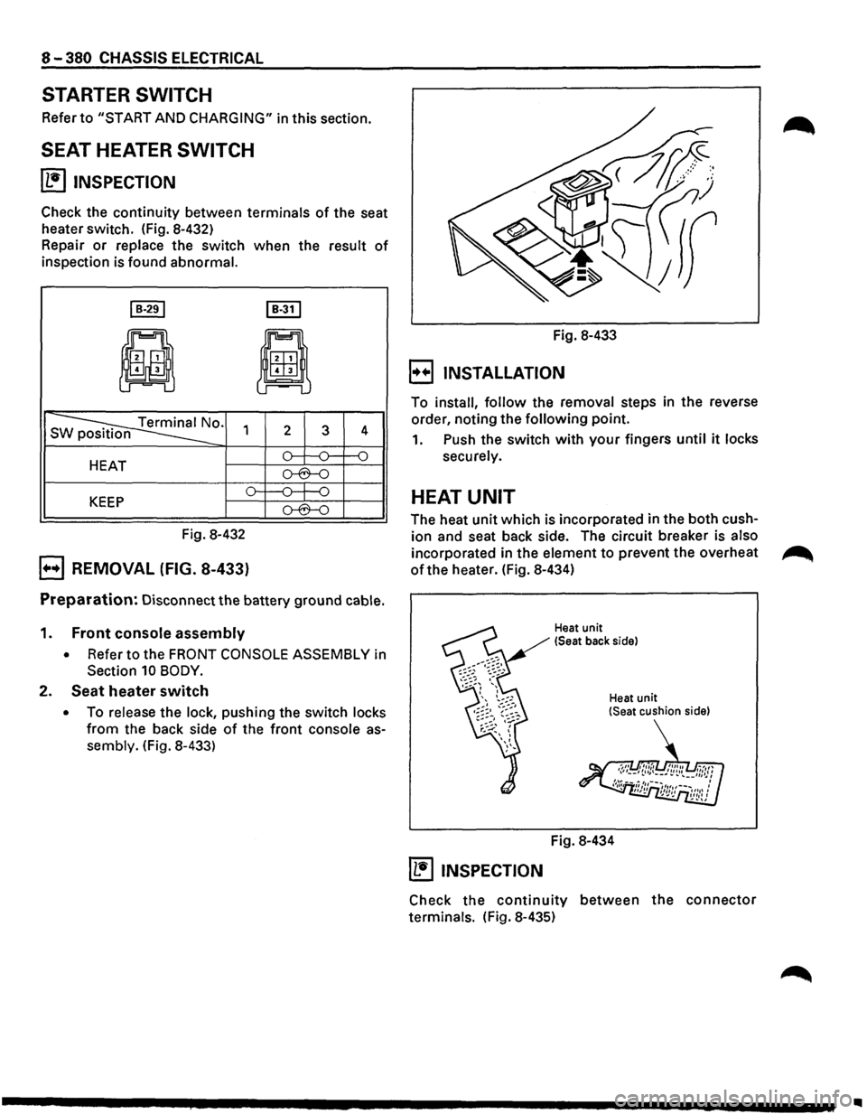
~ INSPECTION
Check the continuity between terminals of the seat
heater switch. (Fig. 8-432)
Repair
or replace the switch when the result of
inspection is found abnormal.
I B-291 I B-31 I
ji
8
s ~0. 1 2 3 4
HEAT o--:---0= f--0
o-6--0
o---0---j-0 KEEP o-6--0
Fig. 8-432
B REMOVAL (FIG. 8-433)
Preparation: Disconnect the battery ground cable.
1. Front console assembly
• Refer to the FRONT CONSOLE ASSEMBLY in
Section 10 BODY.
2. Seat heater switch
• To release the lock, pushing the switch locks
from the back side of the front console as
sembly. (Fig. 8-433) Fig.
8-433
B INSTALLATION
To install, follow the removal steps in the reverse
order, noting the
following point.
1. Push the switch with your fingers until it locks
securely.
HEAT UNIT
The heat unit which is incorporated in the both cush
ion and seat back side. The circuit breaker is also
incorporated in the element to prevent the overheat ~
of the heater. (Fig. 8-434)
Heat unit
(Seat back side)
Heat
unit (Seat cushion side)
Fig. 8-434
~ INSPECTION
Check the continuity between the connector
terminals. (Fig. 8-435)
..