air condition ISUZU TROOPER 1995 Workshop Manual
[x] Cancel search | Manufacturer: ISUZU, Model Year: 1995, Model line: TROOPER, Model: ISUZU TROOPER 1995Pages: 1928
Page 505 of 1928
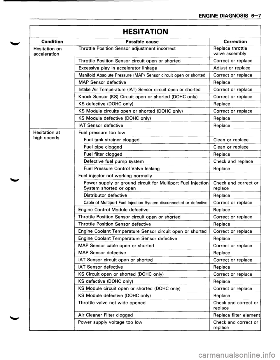
ENGINE DIAGNOSIS 6-7
HESITATION
Condition Possible cause Correction
Hesitation on Throttle
Position Sensor adjustment incorrect Replace
throttle
acceleration valve
assembly
Throttle Position Sensor circuit open
or shorted Correct
or replace
Excessive play in accelerator linkage
Adjust or replace
Manifold Absolute
Pressure (MAP) Sensor circuit open or shorted Correct or replace
MAP Sensor defective Replace
Intake Air
Temperature (IAT) Sensor circuit open or shorted Correct or replace
Knock Sensor
(KS) Circuit open or shorted (DOHC only) Correct or replace
KS defective (DOHC only) Replace
KS Module circuits open or shorted (DOHC only) Correct or replace
KS Module defective (DOHC only) Replace
IAT Sensor defective Replace
Hesitation at
Fuel pressure
too low
high speeds
Fuel tank strainer clogged Clean or replace
Fuel pipe clogged
Clean or replace
Fuel filter clogged
Replace
Defective fuel
pump system Check and replace
Fuel Pressure Control Valve leaking Replace
Fuel injector
not working normally
Power supply or ground circuit for Multipart Fuel Injection Check and correct or
System shorted or open
replace
Distributor defective Replace
Cable of Multipart Fuel Injection System disconnected or defective Correct or replace
Engine Control Module defective Replace
Throttle Position Sensor circuit open
or shorted Correct or replace
Throttle Position Sensor defective Replace
Engine Coolant Temperature Sensor circuit open
or shorted Correct or replace
Engine Coolant Temperature Sensor defective Replace
MAP Sensor cable open
or shorted Correct or replace
MAP Sensor defective
Replace
IAT Sensor circuit open or shorted
Correct or replace
IAT Sensor defective Replace
KS Circuit open or shorted (DOHC only)
Correct or replace
KS defective (DOHC only) Replace
KS Module circuit open or shorted (DOHC only) Correct or replace
KS Module defective (DOHC only) Replace
Throttle valve
not wide opened
Check and correct or
replace
Air Cleaner Filter clogged
Replace filter element
Power supply voltage
too low Check and correct or
replace
Page 506 of 1928
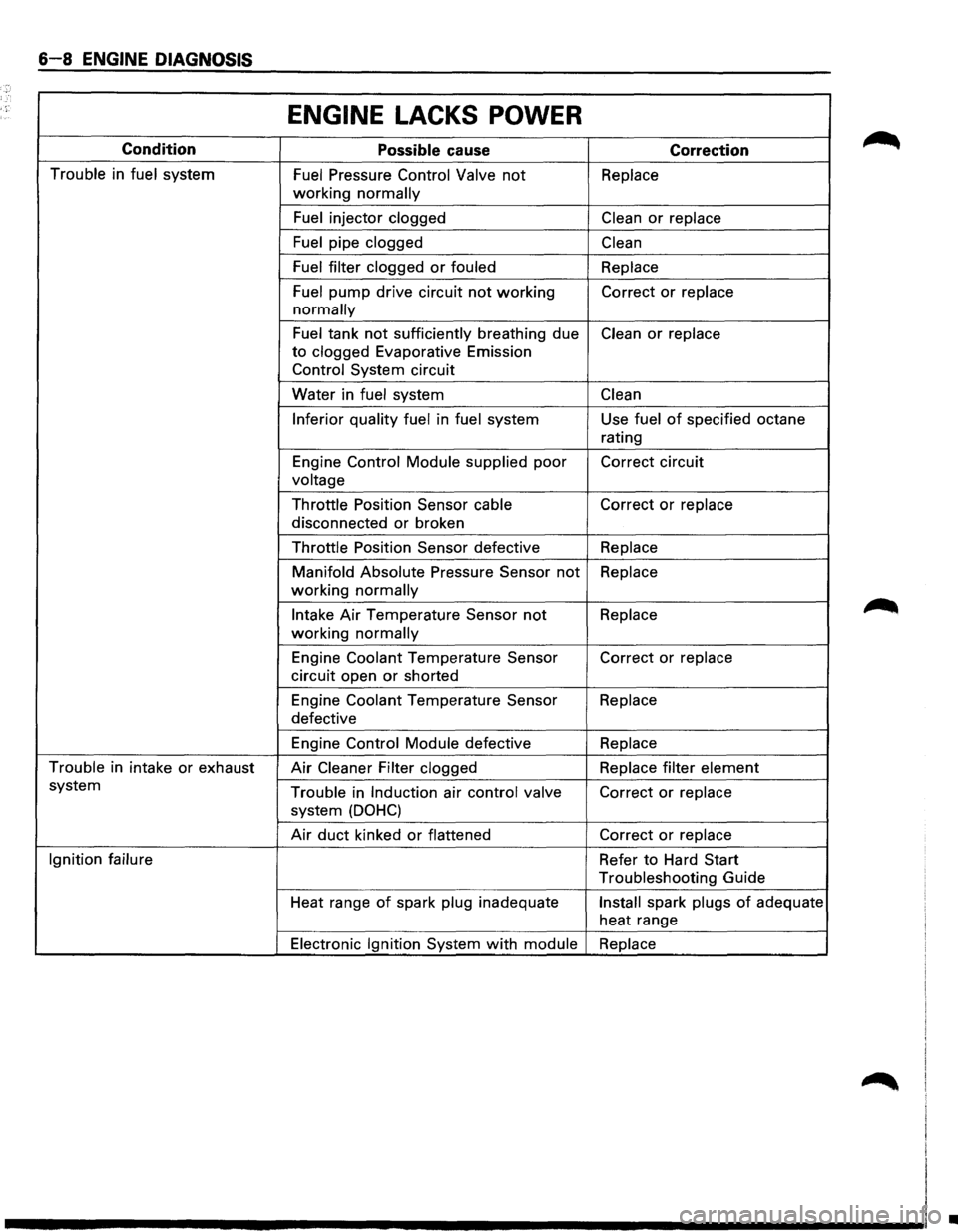
6-8 ENGINE DIAGNOSIS
ENGINE LACKS POWER
Condition
Possible cause Correction
Trouble in fuel system Fuel Pressure Control Valve not Replace
working normally
Fuel
injector clogged Clean or replace
Fuel
pipe clogged Clean
Fuel filter clogged
or fouled Replace
Fuel
pump drive circuit not working Correct or replace
normally
Fuel tank not sufficiently breathing due Clean or replace
to clogged Evaporative Emission
Control System circuit
Water in
fuel system Clean
Inferior quality fuel
in fuel system Use fuel of specified octane
rating
Engine
Control Module supplied poor Correct circuit
voltage
Throttle
Position Sensor cable Correct or replace
disconnected or broken
Throttle Position Sensor defective Replace
Manifold Absolute
Pressure Sensor not Replace
working normally
Intake Air Temperature Sensor not Replace
working normally
Engine Coolant Temperature Sensor Correct or replace
circuit open or shorted
Engine
Coolant Temperature Sensor Replace
defective
Engine
Control Module defective Replace
Trouble
in intake or exhaust Air Cleaner Filter clogged Replace filter element
system Trouble in Induction air control valve Correct or replace
system (DOHC)
Air duct kinked or flattened Correct or replace
Ignition failure
Refer to Hard Start
Troubleshooting Guide
Heat range
of spark plug inadequate Install spark plugs of adequate
heat range
Electronic Ignition System with module Replace
•
Page 512 of 1928
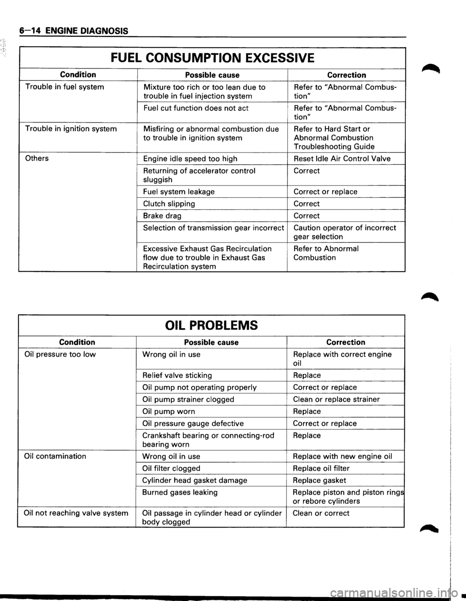
6-14 ENGINE DIAGNOSIS
1;:-
FUEL CONSUMPTION EXCESSIVE
Condition
Possible cause Correction
Trouble in fuel system
Mixture too rich or too lean due to Refer to "Abnormal Combus-
trouble in fuel injection system tion"
Fuel cut function does not act Refer to "Abnormal Combus-
tion"
Trouble in ignition system
Misfiring or abnormal combustion due Refer to Hard Start or
to trouble in ignition system Abnormal Combustion
Troubleshooting Guide
Others Engine idle speed too high Reset Idle Air Control Valve
Returning
of accelerator control Correct
sluggish
Fuel system leakage
Correct or replace
Clutch slipping Correct
Brake drag Correct
Selection of transmission gear incorrect Caution operator of incorrect
gear selection
Excessive Exhaust
Gas Recirculation Refer to Abnormal
flow due to trouble in Exhaust Gas Combustion
Recirculation system
OIL PROBLEMS
Condition
Possible cause Correction
Oil pressure too low Wrong oil in use Replace with correct
engine
oil
Relief valve sticking Replace
Oil pump not operating
properly Correct or replace
Oil pump strainer clogged Clean or replace strainer
Oil pump worn Replace
Oil pressure gauge defective Correct or replace
Crankshaft bearing or connecting-rod Replace
bearing
worn
Oil contamination Wrong oil in use Replace with new engine
oil
Oil filter clogged Replace oil filter
Cylinder head gasket damage Replace
gasket
Burned gases leaking Replace piston and piston rings
or rebore cylinders
Oil not reaching valve system Oil passage in cylinder head or cylinder Clean or correct
body clogged
•
Page 518 of 1928
6A-2 GENERAL ENGINE MECHANICAL
NOTE:
•
During disassembly, be sure that the valve train
components are kept
together and identified so
that they can be re-installed in their original
locations.
• Before removing the cylinder head from the
engine and before disassembling the valve
mechanism, perform a compression test and note
the results.
1•! .. 1 DISASSEMBLY
(SOHC)
1. Camshaft timing pulley
2. Front plate
3. Camshaft bracket fixing bolts
4. Camshaft, oil seal and camshaft end plug
• Remove them with camshaft bracket.
5. Rockershaft assembly (Exhaust side)
6. Rockershaft assembly (Intake side)
7. Spark plug
\fl CAUTION:
VI • Do not remove the spark plugs when the head
and plugs are hot.
• Clean dirt and debris from spark plug recess
areas.
(DOHC)
1. Camshaft timing pulley
2. Front plate
3. Camshaft bracket fixing bolts
4. Chain tensioner fixing bolts
5. Camshaft, oil seal and camshaft end plug
• Remove them with chain and chain tensioner
6. Swing arm.
7. Hydraulic lash adjusters (HLA)
NOTE:
Immerse HLA in engine oil, taking care nottoturn it
upside down or sideways in order to prevent any
air
from entering into HLA.
8. Spark plug
\flCAUTION:
VI • Do not remove the spark plugs when the head
and plugs are hot.
• Clean dirt and debris from spark plug recess
areas.
f}l CLEAN
• Cylinder head
Carefully remove
all varnish, soot and carbon
to the bare metal. Do not use a motorized wire
brush on any gasket sealing surface.
IL'~'IINSPECTION AND REPAIR
• Cylinder head gasket and mating surfaces for
leaks, corrosion and blow-by. If the gasket has
failed, determine the cause. Insufficient
torque on head bolts
Improper installation
Loose
or warped cylinder head
Missing
dowel pins
- Warped case surface
1. Cylinder head bolts for damaged threads or
stretching and damaged heads caused by
improper use of tools.
\fl CAUTION:
VI Replace used cylinder head bolts.
2. Cylinder head for cracks, especially between valve
seats and in the exhaust ports.
3. Cylinder head deck for corrosion, sand particles in
head and porosity.
\fl CAUTION:
VI Do not attemptto weld the cylinder head. Replace
it.
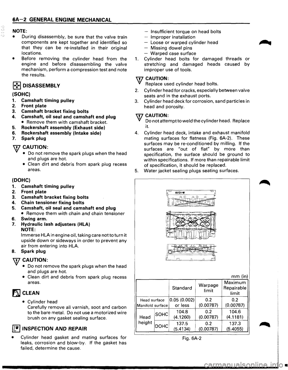
4. Cylinder head deck, intake and exhaust manifold
mating surfaces for flatness (Fig. 6A-2). These
surfaces
may be re-conditioned by milling. If the
surfaces are
"out of flat" by more than
specification, the surface should be ground
to
within specifications. If more than repairable limit
of specification, it should be replaced.
5. Water jacket sealing plugs seating surfaces.
IIVD1-w 8~
~ I 0 I ' 0 0 I 0
mm (in)
Warpage
Maximum
Standard Repairable limit limit
Head surface 0.05 (0.002) 0.2
0.2
Manifold surface or less (0.00787) (0.00787)
SOHC 104.8 0.2
104.6
Head (4.1260) (0.00787) (4.1181)
height
DOHC 137.5 0.2 137.3
(5.4134)
(0.00787) (5.4055)
Fig. 6A-2
•
Page 521 of 1928
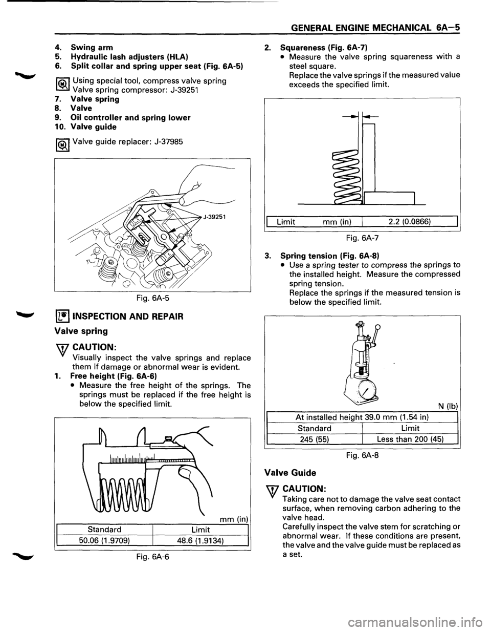
4. Swing arm
5. Hydraulic lash adjusters (HLA)
6. Split collar and spring upper seat (Fig. 6A-5)
l'iS\1 Using special tool, compress valve spring
~ Valve spring compressor: J-39251
7. Valve spring
8.
Valve
9. Oil controller and spring lower
10. Valve guide
1®..1 Valve guide replacer: J-37985
Fig. 6A-5
IL•IINSPECTION AND REPAIR
Valve spring
\fCAUTION:
Visually inspect the valve springs and replace
them
if damage or abnormal wear is evident.
1. Free height (Fig. 6A-6)
• Measure the free height of the springs. The
springs
must be replaced if the free height is
below the specified limit.
mm (in)
Standard Limit
50.06 (1.9709)
48.6 (1.9134)
Fig. 6A-6
GENERAL ENGINE MECHANICAL 6A-5
2. Squareness (Fig. 6A-7)
• Measure the valve spring squareness with a
steel square.
Replace the
valve springs if the measured value
exceeds the specified limit.
Limit mm (in) 2.2 (0.0866)
Fig. 6A-7
3. Spring tension (Fig. 6A-8)
• Use a spring tester to compress the springs to
the installed height. Measure the compressed
spring tension.
Replace the springs
if the measured tension is
below the specified limit.
N
(lb)
At installed height 39.0 mm (1.54 in)
Standard Limit
245
(55) Less than 200 (45)
Fig. 6A-8
Valve Guide
\fCAUTION:
Taking care not to damage the valve seat contact
surface, when removing carbon adhering to the
valve head.
Carefully inspect the valve stem for scratching or
abnormal wear.
If these conditions are present,
the
valve and the valve guide must be replaced as
a set.
Page 536 of 1928
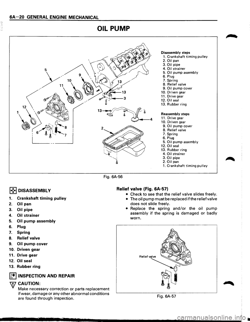
6A-20 GENERAL ENGINE MECHANICAL
OIL PUMP
Fig. 6A-56
Disassembly steps 1. Crankshaft timing pulley 2. Oil pan 3. Oil pipe
4. Oi I strainer 5. Oil pump assembly 6. Plug 7. Spring
8. Relief valve 9. Oil pump cover 10. Driven gear 11. Drive gear 12. Oil seal 13. Rubber ring
Reassembly steps
11. Drive
gear 10. Driven gear 9. Oil pump cover
8. Relief valve 7. Spring
6. Plug 5. Oil pump assembly 12. Oil seal 13. Rubber ring
4. Oil strainer
3. Oil pipe 2. Oil pan 1. Crankshaft timing pulley
l•!•l DISASSEMBLY Relief
valve (Fig. 6A-57)
1. Crankshaft timing pulley
2. Oil pan
3. Oil pipe
4. Oil strainer
5. Oil pump assembly
6. Plug
7. Spring
8. Relief valve
9. Oil pump cover
10. Driven gear
11. Drive gear
12. Oil seal
13. Rubber ring
~ INSPECTION AND REPAIR
\fl CAUTION:
VI Make necessary correction or parts replacement
if wear, damage or any other abnormal conditions
are found through inspection.
• Check to see that the relief valve slides freely.
• The oil pump must be replaced ifthe relief valve
does
not slide freely.
• Replace the spring and/or the oil pump
assembly if the spring is damaged or badly
worn.
Fig. 6A-57
•
Page 547 of 1928
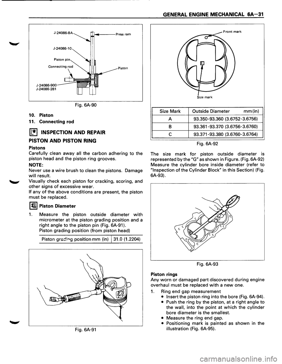
J-24086-SA ~---Press ram
Fig. 6A-90
10. Piston
11. Connecting rod
[1!) INSPECTION AND REPAIR
PISTON
AND PISTON RING
Pistons
Piston
Carefully clean away all the carbon adhering to the
piston head and the piston ring grooves.
NOTE:
Never use a wire brush to clean the pistons. Damage
will result.
Visually
check each piston for cracking, scoring, and
other signs
of excessive wear.
If any of the above conditions are present, the piston
must be replaced.
1~1 Piston Diameter
1. Measure the piston outside diameter with
micrometer at the piston grading position and a
right
angle to the piston pin (Fig. 6A-91 ).
Piston grading position (from piston head)
Piston
grc;d~"g position mm (in) 131.0 (1.2204)
Fig. 6A-91
GENERAL ENGINE MECHANICAL &A-31
Size Mark Outside
Diameter mm (in)
A 93.350-93.360 (3.6752-3.6756)
8 93.361 -93.370 (3.6756-3.6760)
c 93.371-93.380 (3.6760-3.6764)
Fig. 6A-92
The size mark
for piston outside diameter is
represented
by the "G" as shown in Figure. (Fig. 6A-92)
Measure the
cylinder bore inside diameter (refer to
"Inspection of the Cylinder Block" in this Section) (Fig.
6A-93).
Fig. 6A-93
Piston rings
Any worn or damaged part discovered during engine
overhaul must be replaced with a new one.
1. Ring end gap measurement
• Insert the piston ring into the bore (Fig. 6A-94).
• Push the ring by the piston, at a right angle to
the
wall, into the point at which the cylinder
bore diameter is the smallest.
•
Measure the ring end gap.
• Positioning mark is painted as shown in the
illustration (Fig. 6A-95).
Page 578 of 1928
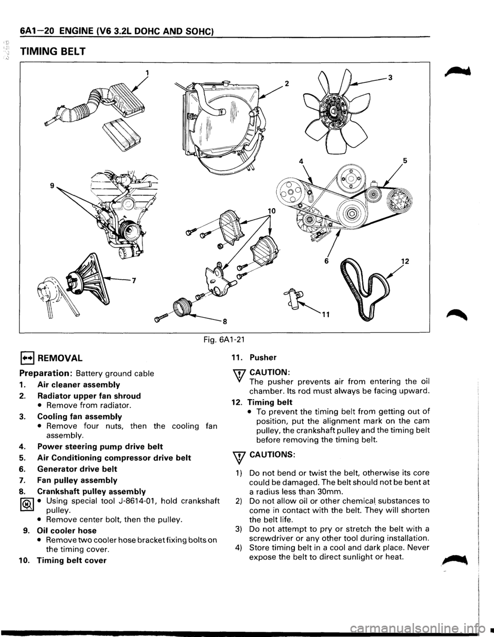
·,'
6A1-20 ENGINE (V6 3.2L DOHC AND SOHC)
TIMING BELT
1 3
2
6 12
~ ..
Fig. 6A1-21
1••1 REMOVAL
Preparation: Battery ground cable
1. Air cleaner assembly
2. Radiator upper fan shroud
• Remove from radiator.
3. Cooling fan assembly
• Remove four nuts, then the cooling fan
assembly.
4. Power steering pump drive belt
5. Air Conditioning compressor drive belt
6. Generator drive belt
7. Fan pulley assembly
8. Crankshaft pulley assembly
~ • Using special tool J-8614-01, hold crankshaft
~ pulley.
•
Remove center bolt, then the pulley.
9. Oil cooler hose
• Remove two cooler hose bracket fixing bolts on
the timing cover.
10. Timing belt cover 11.
Pusher
'IT7 CAUTION:
'if The pusher prevents air from entering the oil
chamber. Its rod must always be facing upward.
12. Timing belt
• To prevent the timing belt from getting out of
position, put the alignment mark on the cam
pulley, the crankshaft pulley and the timing belt
before removing the timing belt.
w CAUTIONS:
1) Do not bend or twist the belt, otherwise its core
could be damaged. The belt should not be bent at
a radius
less than 30mm.
2) Do not allow oil or other chemica[ substances to
come in contact with the belt. They will shorten
the
belt life.
3) Do not attempt to pry or stretch the belt with a
screwdriver or any other tool during installation.
4) Store timing belt in a cool and dark place. Never
expose the
belt to direct sunlight or heat. ~
•
Page 581 of 1928
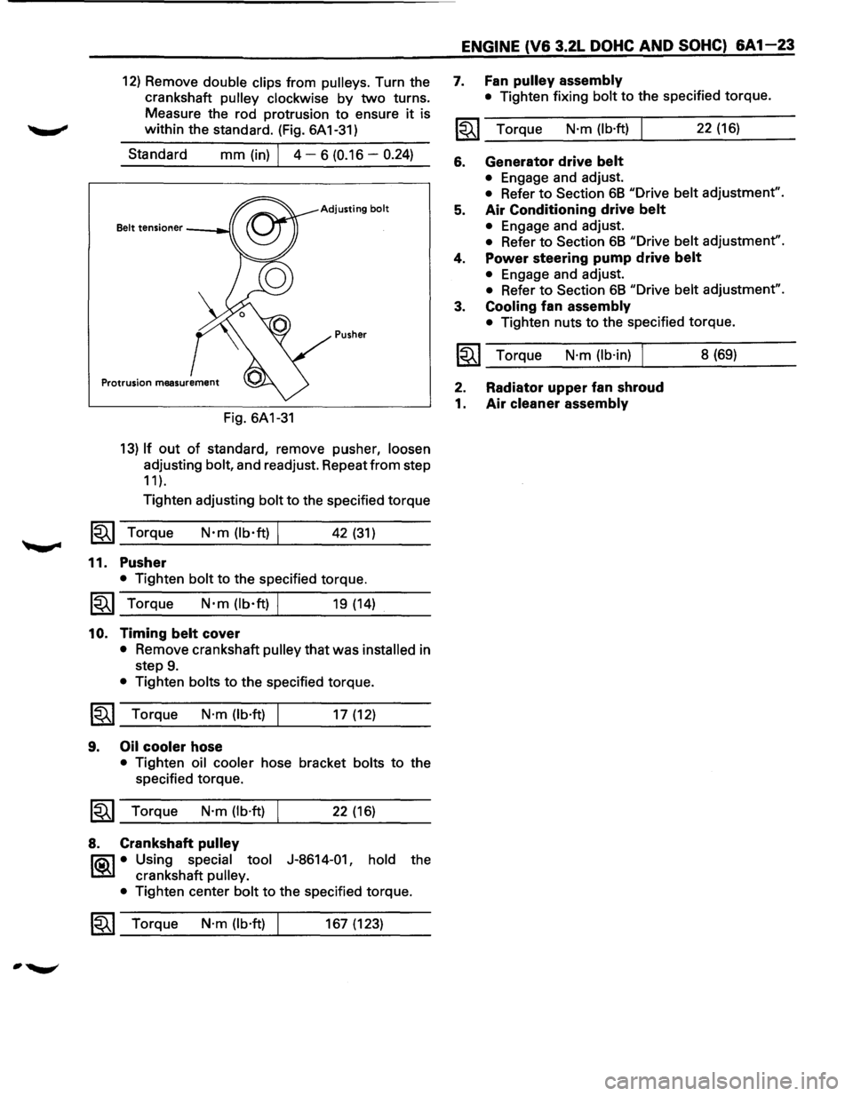
12) Remove double clips from pulleys. Turn the
crankshaft
pulley clockwise by two turns.
Measure the rod protrusion to ensure
it is
within the standard. (Fig. 6A 1-31)
Standard
mm (in) I 4 - 6 (0.16 -0.24)
Adjusting bolt
Pusher
Fig. 6A1-31
13) If out of standard, remove pusher, loosen
adjusting bolt, and readjust. Repeat from step
11 ).
Tighten adjusting bolt to the specified torque
1~1 Torque N·m (lb·ft) I 42 (31)
11. Pusher
• Tighten bolt to the specified torque.
1~1 Torque N·m (lb·ft) I 19 (14)
10. Timing belt cover
• Remove crankshaft pulley that was installed in
step
9.
• Tighten bolts to the specified torque.
~~~ Torque N·m (lb·ft) I 17 (12)
9. Oil cooler hose
• Tighten oil cooler hose bracket bolts to the
specified torque.
~~~ Torque N·m (lb·ft) I 22 (16)
8. Crankshaft pulley
l"iQ\1 • Using special tool J-8614-01, hold the
~ crankshaft pulley.
•
Tighten center bolt to the specified torque.
1~1 Torque N·m (lb·ft) 167 (123)
ENGINE (V6 3.2L DOHC AND SOHC) 6A1-23
7. Fan pulley assembly
• Tighten fixing bolt to the specified torque.
~~~ Torque N·m (lb·ft) 22 (16)
6. Generator drive belt
• Engage and adjust.
• Refer to Section 68 "Drive belt adjustment".
5. Air Conditioning drive belt
• Engage and adjust.
• Refer to Section 68 "Drive belt adjustment".
4. Power steering pump drive belt
• Engage and adjust.
• Refer to Section 68 "Drive belt adjustment".
3. Cooling fan assembly
• Tighten nuts to the specified torque.
~~~ Torque N·m (lb·in) I 8 (69)
2. Radiator upper fan shroud
1. Air cleaner assembly
Page 582 of 1928
, r;
6A 1-24 ENGINE (V6 3.2L DOHC AND SOHC)
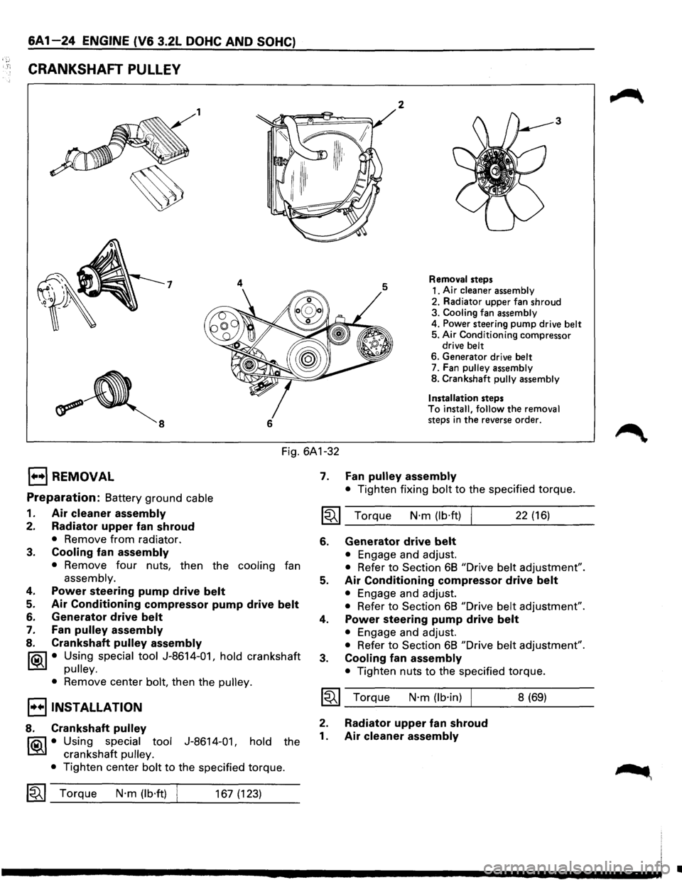
CRANKSHAFT PULLEY
1 2
7 4
6
3
Removal steps
1. Air
cleaner assembly
2. Radiator upper fan shroud
3. Cooling fan assembly
4. Power steering pump drive belt 5. Air Conditioning compressor
drive belt
6. Generator drive belt 7. Fan pulley assembly
8. Crankshaft pully assembly
Installation
steps To install, follow the removal steps in the reverse order.
Fig. 6A1-32
E) REMOVAL
Preparation: Battery ground cable
1. Air cleaner assembly
2. Radiator upper fan shroud
• Remove from radiator.
3. Cooling fan assembly
• Remove four nuts, then the cooling fan
assembly.
4. Power steering pump drive belt
5. Air Conditioning compressor pump drive belt
6. Generator drive belt
7. Fan pulley assembly
8. Crankshaft pulley assembly
IQil • Using special tool J-8614-01, hold crankshaft
I.:Sil pulley.
•
Remove center bolt, then the pulley.
I••IINSTALLATION
8. Crankshaft pulley
IQil • Using special tool J-8614-01, hold the
I.:Sil crankshaft pulley.
•
Tighten center bolt to the specified torque.
1~1 Torque N·m (lb·ft) 167 (123)
7. Fan pulley assembly
• Tighten fixing bolt to the specified torque.
1~1 Torque N·m (lb·ft) 22 (16)
6. Generator drive belt
• Engage and adjust.
• Refer to Section 68 "Drive belt adjustment".
5. Air Conditioning compressor drive belt
• Engage and adjust.
• Refer to Section 68 "Drive belt adjustment".
4. Power steering pump drive belt
• Engage and adjust.
• Refer to Section 68 "Drive belt adjustment".
3. Cooling fan assembly
• Tighten nuts to the specified torque.
~~~ Torque N·m (lb·in) I
2. Radiator upper fan shroud
1. Air cleaner assembly
8 (69)
•