air condition ISUZU TROOPER 1995 Workshop Manual
[x] Cancel search | Manufacturer: ISUZU, Model Year: 1995, Model line: TROOPER, Model: ISUZU TROOPER 1995Pages: 1928
Page 605 of 1928
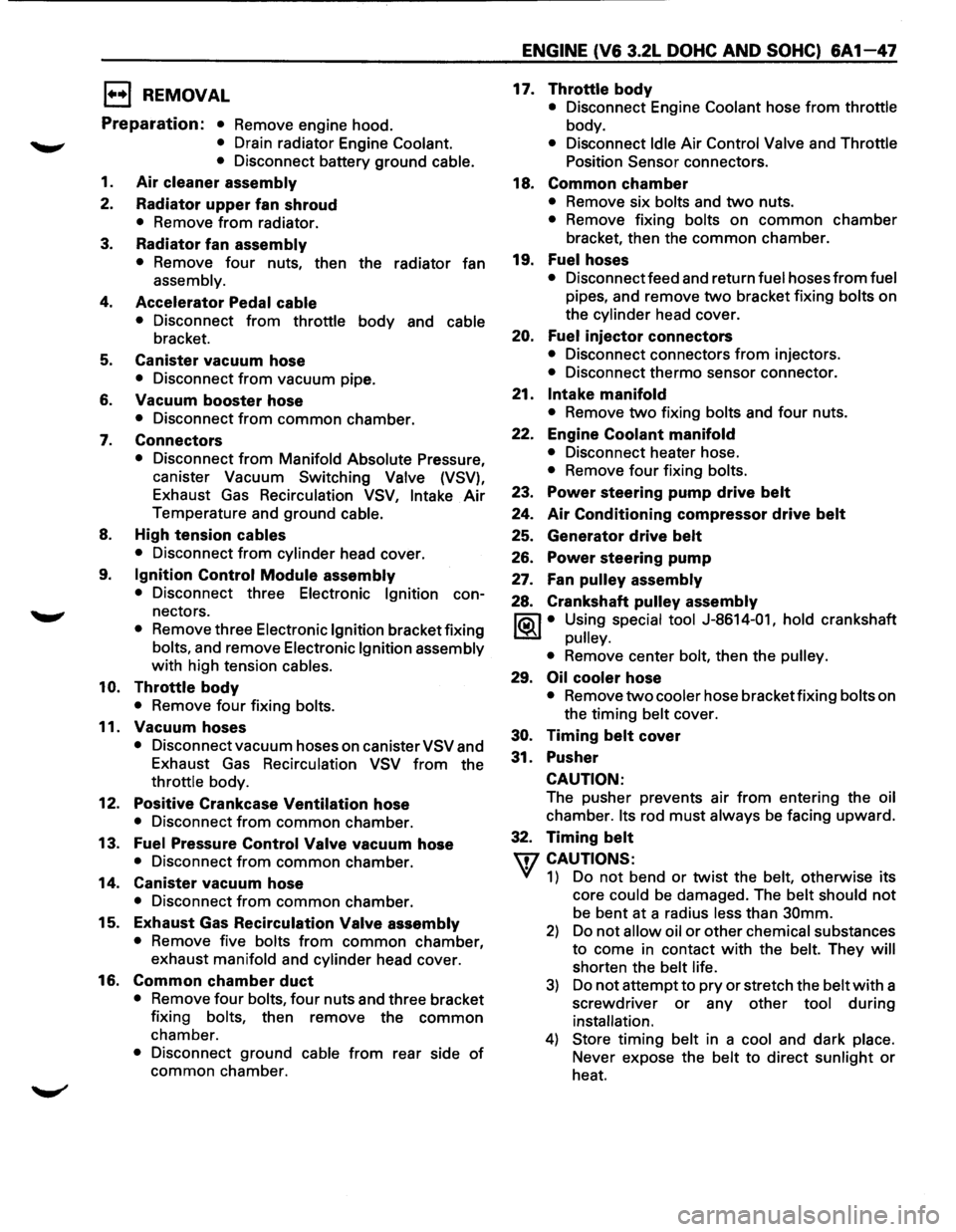
1••1 REMOVAL
Preparation: • Remove engine hood.
• Drain radiator Engine Coolant.
•
Disconnect battery ground cable.
1.
Air cleaner assembly
2. Radiator upper fan shroud
• Remove from radiator.
3. Radiator fan assembly
• Remove four nuts, then the radiator fan
assembly.
4. Accelerator Pedal cable
• Disconnect from throttle body and cable
bracket.
5. Canister vacuum hose
• Disconnect from vacuum pipe.
6.
Vacuum booster hose
• Disconnect from common chamber.
7. Connectors
• Disconnect from Manifold Absolute Pressure,
canister Vacuum Switching Valve (VSV),
Exhaust
Gas Recirculation VSV, Intake Air
Temperature and ground cable.
8. High tension cables
• Disconnect from cylinder head cover.
9. Ignition Control Module assembly
• Disconnect three Electronic Ignition con
nectors.
• Remove three Electronic Ignition bracket fixing
bolts, and remove Electronic
Ignition assembly
with high tension cables.
10. Throttle body
• Remove four fixing bolts.
11.
Vacuum hoses
• Disconnect vacuum hoses on canister VSV and
Exhaust
Gas Recirculation VSV from the
throttle body.
12.
Positive Crankcase Ventilation hose
• Disconnect from common chamber.
13. Fuel Pressure
Control Valve vacuum hose
• Disconnect from common chamber.
14.
Canister vacuum hose
• Disconnect from common chamber.
15.
Exhaust Gas Recirculation Valve assembly
• Remove five bolts from common chamber,
exhaust manifold and cylinder head cover.
16.
Common chamber duct
• Remove four bolts, four nuts and three bracket
fixing bolts, then remove the
common
chamber.
• Disconnect ground cable from rear side of
common chamber.
ENGINE (V6 3.2L DOHC AND SOHC) 6A1 47
17. Throttle body
• Disconnect Engine Coolant hose from throttle
body.
• Disconnect Idle Air Control Valve and Throttle
Position Sensor connectors.
18.
Common chamber
• Remove six bolts and two nuts.
• Remove fixing bolts on common chamber
bracket, then the
common chamber.
19.
Fuelhoses
• Disconnect feed and return fuel hoses from fuel
pipes, and remove
two bracket fixing bolts on
the cylinder head cover.
20. Fuel injector connectors
• Disconnect connectors from injectors.
• Disconnect thermo sensor connector.
21.
Intake manifold
• Remove two fixing bolts and four nuts.
22. Engine
Coolant manifold
• Disconnect heater hose.
• Remove four fixing bolts.
23.
Power steering pump drive belt
24. Air Conditioning compressor drive belt
25. Generator drive belt
26. Power steering pump
27. Fan pulley assembly
28. Crankshaft pulley assembly
I®J • Using special tool J-8614-01, hold crankshaft
pulley.
•
Remove center bolt, then the pulley.
29. Oil cooler hose
• Remove two cooler hose bracket fixing bolts on
the timing belt cover.
30. Timing belt cover
31. Pusher
CAUTION:
The pusher prevents air from entering the oil
chamber. Its rod must always be facing upward.
32.
Timing belt
w CAUTIONS:
' 1) Do not bend or twist the belt, otherwise its
core could
be damaged. The belt should not
be bent at a radius less than 30mm.
2) Do not allow oil or other chemical substances
to come in contact
with the belt. They will
shorten the belt life.
3) Do not attempt to pry or stretch the belt with a
screwdriver
or any other tool during
installation.
4) Store timing belt in a cool and dark place.
Never expose the belt to direct sunlight
or
heat.
Page 606 of 1928
~:· T·, ·.}:
6A1-48 ENGINE (V6 3.2L DOHC AND SOHC)
33. Cylinder head cover
• Remove 11 fixing bolts, then the cylinder head
cover.
34. Power steering pump bracket
• Disconnect ground cable from bracket.
35.
• Remove five fixing bolts, then the bracket.
Exhaust front pipe
36.
37. Level gage fixing bolt
• Remove from cylinder head.
Cylinder head
1••1 INSTALLATION
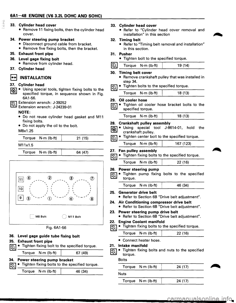
37. Cylinder head
li0\1 • Using special tools, tighten fixing bolts to the
~ specified torque, in sequence shown in Fig.
6A1-56.
~ Extension wrench: J-39252
t:6.l Extension wrench: J-24239-01
NOTE:
• Do not reuse cylinder head gasket and M11
fixing bolts.
•
Do not apply the oil to the bolt.
M8x1.25
Torque
N·m (lb·ft) 21 (15)
M11x1.5
Torque
N·m (lb·ft) 64 (47)
OJ] ® ® ® , ' ' ,
, I , ,
[IQJ ' I I
I I
I I I
I I
I I I
I I
,
[I] ' , , ' @ ' ,
CD ' , , __
@
[[ M8 Bolt (J M11 Bolt
Fig.
6A1-56
36. Level gage guide tube fixing bolt
35. Exhaust front pipe
'
,
(])
I
I
I
,
@
~~~ • Tighten fixing bolt to the specified torque.
Torque
N·m (lb·ft) I 67 (49)
34. Power steering pump bracket
~~~ • Tighten fixing bolts to the specified torque.
Torque
N·m (lb·ft) I 46 (34)
33.
32.
31.
Cylinder head cover
• Refer to "Cylinder head cover removal and
installation" in this section
Timing belt
• Refer to "Timing belt removal and installation"
in this section.
Pusher
• Tighten bolt to the specified torque.
I~I __ T_o_r~qu_e __ N_·_m~(lb_·ft_)~ ______ 1_9_(1_4_) ____ _
30. Timing belt cover
• Remove crankshaft pulley that was installed in
step 34.
~~~· Tighten bolts to the specified torque.
Torque
N·m (lb·ft) I 18 (13)
29. Oil cooler hose
~ • Tighten oil cooler hose bracket bolts to the
t:6.l specified torque.
Torque
N·m (lb·ft) I 18 (13)
28. Crankshaft pulley assembly
li0\1 • Using special tool J-8614-011 hold the
~ crankshaft pulley.
~~~ • Tighten center bolt to the specified torque.
Torque
N·m (lb·ft) I 167 (123)
27. Fan pulley assembly
~~~· Tighten fixing bolts to the specified torque.
Torque
N·m (lb·ft) I 22 (16)
26. Power steering pump
~ • Tighten pump fixing bolts to the specified
t:6.l torque.
Torque
N·m (lb·ft) I 46 (34)
25. Generator drive belt
• Refer to Section 68 "Drive belt adjustment".
24.
Air Conditioning compressor drive belt
• Refer to Section 68 "Drive belt adjustment".
23. Power steering pump drive belt
• Refer to Section 68 "Drive belt adjustment".
22. Engine Coolant manifold
~~~· Tighten fixing bolts to the specified torque.
Torque
N·m (lb·ft) I 22 (16)
• Connect heater hose.
21.
Intake manifold
~ • Tighten fixing bolts and nuts to the specified
t:6.l torque.
Bolts
Torque N·m (lb·ft) 24 (17)
Nuts
Torque
N·m (lb·ft) 24 (17)
..
Page 620 of 1928
'.n
6A1-62 ENGINE (V6 3.2L DOHC AND SOHC)
E) REMOVAL
Preparation: • Disconnect battery ground cable.
• Remove engine hood.
In order to return the hood to the
original position exactly, make
alignment on the hood and hinges
before
removal.
•
Drain radiator coolant.
1. Accelerator cable
• Disconnect from throttle valve and common
chamber.
2. Ventilation hose
3.
Air hose
4. Air cleaner assembly
5. Canister vacuum hose
6. Vacuum booster hose
7. Engine harness connectors
• Disconnect three connectors on canister side.
8. Battery ground cables
• Disconnect two black and white connector
clips
from the power steering pump bracket.
9. Ground cables
• Disconnect two terminals connected to the
battery support and the
front right frame.
1 0. Bonding cable connector
• Disconnect connector on the left side dash
panel.
11. Bonding cable terminal
• Disconnect terminal on the back of left bank.
12. Starter harness connector
• Disconnect from starter.
13. Radiator
• Disconnect upper and lower hoses from the
engine.
• Disconnect coolant reserve tank hose from
radiator.
• Disconnect ATF hose from the pipe. (A/T)
• Remove radiator lower hose clip from the hose
bracket.
• Remove radiator lower fan shroud.
• Remove radiator.
14. Power steering pump drive belt
15. Power steering pump
• Remove two bolts on the bracket, and place the
pump along with piping on the body side.
16. Air Conditioning compressor drive belt
17. Air Conditioning compressor
• Remove fixing bolts and shift aside the
compressor
with piping attached.
18. Heater hoses
• Disconnect two hoses from the engine.
19. ATF pipes
• Disconnect two pipes from right side engine
mount.
20. Transmission assembly
• See "Transmission Removal and Installation"
in Section 7.
21. Left side engine mount
• Support the engine.
• Remove two fixing bolts from engine mount on
chassis side.
22. Right side engine mount
• Remove two fixing bolts from engine mount on
chassis side.
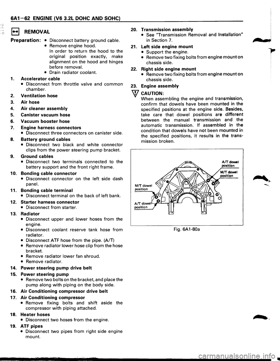
23. Engine assembly
w CAUTION:
When assembling the engine and transmission,
confirm
that dowels have been mounted in the
specified positions at the engine side. Besides,
take care
that dowel positions are different
between the manual transmission and the
automatic transmission.
If assembled in the
condition that dowels have not been mounted in
the specified positions,
it results in the trans
mission broken.
M/Tdowel position
AIT doweiY~--r..ri~-' position
Fig. 6A1-80a
n t b,
•
Page 631 of 1928
Mixing ratio(%) 0 10 20 30 40 50
~
' -10
'
1
' -30
~ -40
In case of 8.5 lit total cooling system capacity
Mixing Anti-freeze
Water: solution: ratio (%) lit. (U.S. gal) lit. (U.S. gal.)
0 0 0
8.5 (2.2) 10 0.9 (0.3) 7.6 (2.0) 15
1.3 (0.4) 7.2 (1.9) 20 1.7 (0.5) 6.8 (1.8)
25 2.1 (0.6) 6.4 (1.7) 30 2.6 (0.7) 5.9 (1.6)
35 3.0 (0.8) 5.5
(1.5) 40 3.4 (0.9) 5.1 (1.3)
45 3.8 (1.0) 4.7 (1.2) 50 4.3 (1.1)
4.2 (1.1)
Fig. 68-5
ENGINE COOLING 68-3
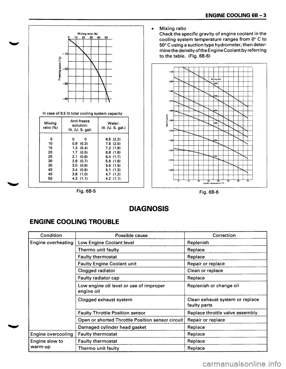
• Mixing ratio
Check
the specific gravity of engine coolant in the
cooling system temperature ranges from oo C to
50° C using a suction type hydrometer, then deter
mine the densityofthe Engine Coolant by referring
to the table. (Fig. 68-6)
1,100 1'-........ ........ ...... .............. Mixing ratio
~"""--r-... 1'-""' 1,1)90
........ ...... ........ ........ .......... '
1,000
'"" 1,07 o......_ 1'-........ I'-.......... I"-........ .......
I"-........ ..........
................. I"-........
'
1,080
....... I"-........ ~ ........ ......
........ "'" ~"""--r--..... 1,050
r-. ........ ~ .......... ......
---
........ ........ 1,040
r-.... !'--.. 1'-0 '"" ~"""--1'-.... ........ 1,03
1--....... ........ r--~ ........
'
1,020
....... ~ 1'-0 ~"""---.... 1,01
...... ,
'
1,000
10 20 30 40 50 60 70 Coolant temperature ("C)
Fig. 68-6
DIAGNOSIS
ENGINE COOLING TROUBLE
Condition Possible cause Correction
Engine
overheating Low Engine Coolant level Replenish
Thermo unit faulty Replace
Faulty
thermostat Replace
Faulty
Engine Coolant unit Repair or replace
Clogged
radiator Clean or replace
Faulty
radiator cap Replace
Low engine oil level or use of improper Replenish or change oil
engine oil
Clogged exhaust system Clean exhaust system or replace
faulty parts
Faulty Throttle Position sensor Replace throttle valve assembly
Open or shorted Throttle Position sensor circuit Repair or replace
Damaged cylinder head gasket Replace
Engine overcooling Faulty thermostat Replace
Engine slow to Faulty thermostat Replace
warm-up Thermo unit faulty Replace
Page 636 of 1928
'.,~-' r.
68-8 ENGINE COOLING
2. Radiator hose
• Disconnect inlet hose and outlet hose from the
engine.
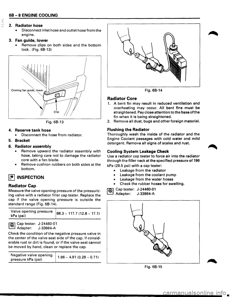
3. Fan guide, lower
• Remove clips on both sides and the bottom
lock. (Fig. 68-13)
~ Cooling fan guide; lower
~
Clip
Fig. 68-13
4. Reserve tank hose
• Disconnect the hose from radiator.
5. Bracket
6. Radiator assembly
• Remove upward the radiator assembly with
hose, taking care not to damage the radiator
core
with a fan blade.
• Remove cushion rubbers on both sides at the
bottom.
~ INSPECTION
Radiator Cap
Measure the valve opening pressure of the pressuriz
ing valve with a radiator filler cap tester. Replace the
cap
if the valve opening pressure is outside the
standard range (Fig. 68-14).
~;!v(~~i~ening pressure 88.3-117.7 (12.8-17.1)
l'i':'il Cap tester: J-24460-01
~ Adapter: J-33984-A
Check the
condition of the negative pressure valve in
the center
of the valve seat side of the cap. If consid
erable rust
or dirt is found, or if the valve seat cannot
be
moved by hand, clean or replace the cap.
Negative
valve opening
pressure kPa (psi) 1.96-4.91 (0.28-0.71)
Fig. 68-14
Radiator Core
1. A bent fin may result in reduced ventilation and
overheating
may occur. All bent fins must be
straightened. Pay
close attention to the base of the
fin when it is being straightened.
2. Remove all dust, bugs and other foreign material.
Flushing the Radiator
Thoroughly wash the inside of the radiator and the
Engine
Coolant passages with cold water and mild
detergent. Remove all signs of scales and rust.
Cooling System Leakage Check
Use a radiator cap tester to force air into the radiator
through the filler neck at the specified pressure of 196
kPa (28.5 psi) with a cap tester:
• Leakage from the radiator
• Leakage from the coolant pump
• Leakage from the water hoses
• Check the rubber hoses for swelling.
rt:\1 Cap tester: J-24460-01
~ Adapter: J-33984-A
Fig. 68-15
•
Page 638 of 1928
68 -10 ENGINE COOLING
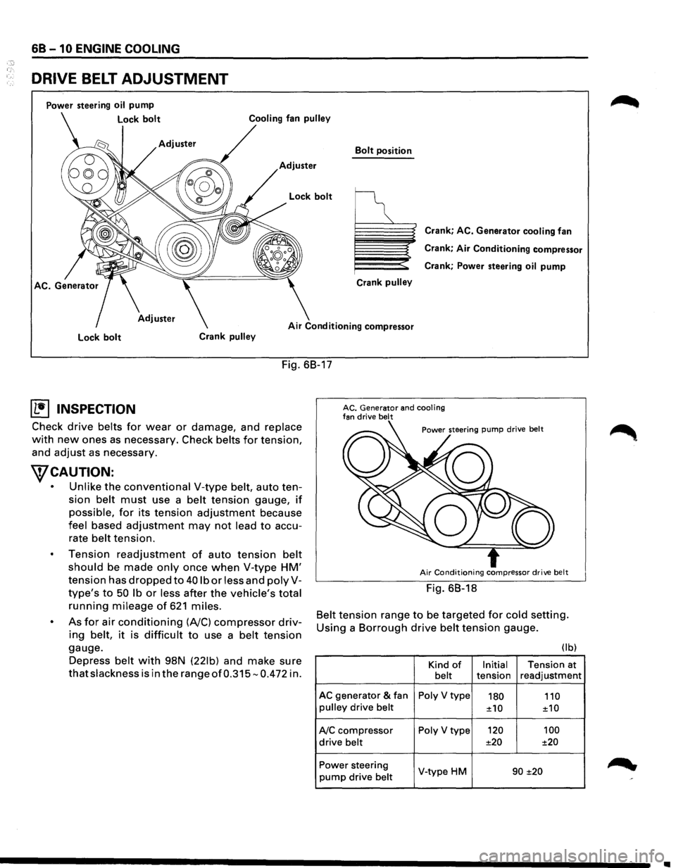
DRIVE BELT ADJUSTMENT
Power steering oil pump
Lock bolt
Bolt position
Adjuster
Crank
pulley
Crank; AC. Generator cooling fan
Crank;
Air Conditioning compressor
Crank; Power steering
oil pump
Air Conditioning compressor
Lock bolt Crank pulley
Fig. 68-17
(b!] INSPECTION
Check drive belts for wear or damage, and replace
with new ones as necessary. Check belts for tension,
and
adjust as necessary.
WCAUTION:
• Unlike the conventional V-type belt, auto ten
sion
belt must use a belt tension gauge, if
possible, for its tension adjustment because
feel based adjustment may not lead to accu
rate
belt tension.
Tension
readjustment of auto tension belt
should be made only once when V-type HM'
tension has dropped to 40 lb or less and polyV
type's to 50 lb or less after the vehicle's total
running mileage of 621 miles.
As for air conditioning (A/C) compressor driv
ing belt, it is difficult to use a belt tension
gauge.
Depress
belt with 98N (221b) and make sure
that slackness is in the range of0.315-0.472 in.
AC. Generator and cooling fan drive belt
Air Conditioning compressor drive belt
Fig. 68-18
Belt tension range to be targeted for cold setting.
Using a
Borrough drive belt tension gauge.
(I b)
Kind of Initial Tension at belt tension readjustment
AC generator & fan Poly V type 180 110 pulley drive belt ±10
±10
A/C compressor Poly V type 120
100
drive belt ±20
±20
Power steering
V-type HM 90 ±20 pump drive belt
•
Page 644 of 1928
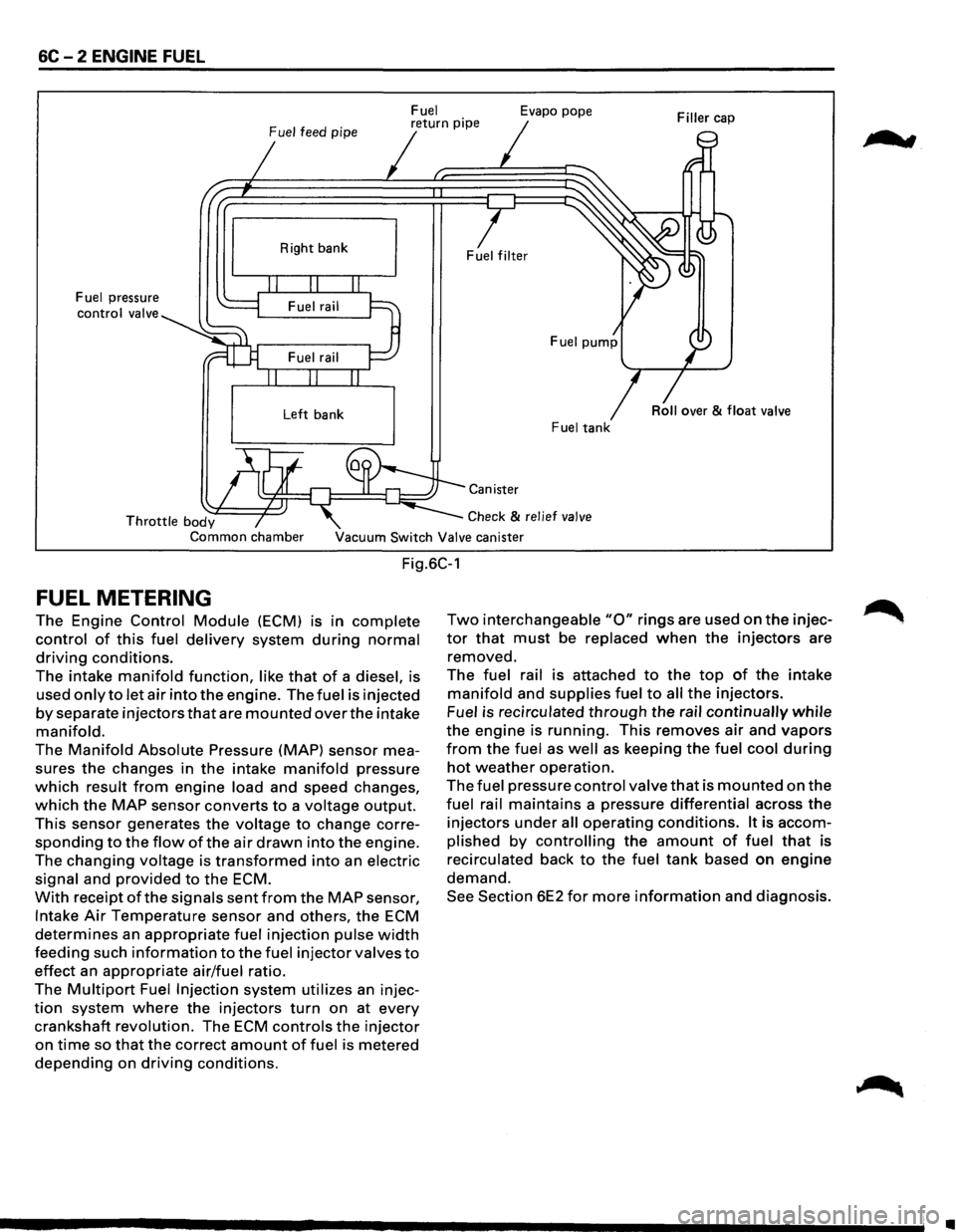
6C - 2 ENGINE FUEL
Fuel
Fuel
feed pipe return pipe Evapo pope
Fuel pressure
control valve Right
bank
Left bank Fuel tank
Canister
Throttle body Common chamber
Check & relief
valve
Vacuum Switch Valve canister
Fig.6C-1
FUEL METERING
The Engine Control Module (ECM) 1s 1n complete
control of this fuel delivery system during normal
driving conditions.
The intake manifold function, like that of a diesel, is
used
only to let air into the engine. The fuel is injected
by separate injectors that are mounted over the intake
manifold.
The Manifold Absolute Pressure (MAP) sensor mea
sures
the changes in the intake manifold pressure
which result from engine load and speed changes,
which the MAP sensor converts to a voltage output.
This sensor generates the voltage to change corre
sponding to the flow ofthe air drawn into the engine.
The
changing voltage is transformed into an electric
signal and provided to the ECM.
With receipt of the signals sent from the MAP sensor,
Intake Air Temperature sensor and others, the ECM
determines an appropriate fuel injection pulse width
feeding such information to the fuel injector valves to
effect an appropriate air/fuel ratio.
The
Multipart Fuel Injection system utilizes an injec
tion system where the injectors turn on at every
crankshaft revolution. The ECM controls the injector
on time so that the correct amount of fuel is metered
depending on driving conditions.
Two interchangeable "0" rings are used on the injec
tor that must be replaced when the injectors are
removed.
The fuel rail is attached to the top of the intake
manifold and supplies fuel to all the injectors.
Fuel is recirculated
through the rail continually while
the engine is running. This removes air and vapors
from the fuel as well as keeping the fuel cool during
hot weather operation.
The fuel pressure control valve that is mounted on the
fuel rail maintains a pressure differential across the
injectors under all operating conditions. It is accom
plished by controlling the amount of fuel that is
recirculated back
to the fuel tank based on engine
demand.
See Section 6E2 for more information and diagnosis.
;au
•
Page 657 of 1928
ENGINE ELECTRICAL 601-3
ON-VEHICLE SERVICE
BATTERY CHARGING
Observe the following safety precautions when
charging the battery:
1. Never attempt to charge the battery when the
fluid level is below the lower level line on the
side
of the battery. In this case, the battery
must be replaced.
2. Pay close attention to the battery during the
charging procedure.
Battery charging
should be discontinued or the
rate
of charge reduced if the battery feels hot
to the touch.
Battery charging
should be discontinued or the
rate
of charge reduced if the battery begins to
gas or spew electrolyte from the vent holes.
3. In order to more easily view the hydrometer
blue dot or ring, it may be necessary to jiggle
or tilt the battery.
4. Battery temperature can have a great effect on
battery charging capacity.
5. The sealed battery used on this vehicle may be
either quick-charged or slow-charged in the
same manner
as other batteries.
Whichever method you decide
to use, be sure
that you
completely charge the battery. Never
partially charge the battery.
JUMP STARTING
JUMP STARTING WITH AN AUXILIARY
(BOOSTER)
BATTERY
W CAUTION:
Never push or tow the vehicle in an attempt to
start it.
Serious damage to the emission sys
tem as
well as other vehicle parts will result.
Treat both the discharged battery and the
booster battery
with great care when using
jumper cables. Carefully follow the jump start
ing procedure, being
careful at all times to
avoid sparking.
wwARNING:
Failure to carefully follow the jump starting
procedure
could result in the following:
1. Serious personal injury, particulaly to your
eyes.
2. Property damage from a battery explo
sion, battery acid, or an electrical fire.
3. Damage to the electronic components of
one or both vehicles particularly.
Never expose the battery to an open flame or elec
trical
spark. Gas generated by the battery may catch
fire
or explode.
Remove any rings, watches, or other jewelry before
working around the battery. Protect
your eyes by
wearing
an approved set of goggles.
Never allow battery fluid to come in contact with
your eyes or skin.
Never
allow battery fluid to come in contact with
fabrics or painted surfaces.
Battery
fluid is a highly corrosive acid.
Should battery fluid come in contact with your eyes,
skin, fabric, or a painted surface,
immediately and
thoroughly rinse the affected area with clean tap
water. Never
allow metal tools or jumper cables to come
in contact with the positive battery
terminal, or any
other
metal surface of the vehicle. This will protect
against a short circuit.
Always keep batteries out of the reach of young
children.
JUMP STARTING PROCEDURE
1. Set the vehicle parking brake.
If the vehicle is equipped with an automatic
transmission,
place the selector lever in the
"PARK" position.
If the vehicle is equipped with a manual trans
mission
place the shift lever in the "NEUTRAL"
position.
Turn
"OFF" the ignition.
Turn
"OFF" all lights and any other accessory
requiring
electrical power.
2. Look at the built-in hydrometer.
If the indication area of the built-in hydrometer
is
completely clear, do not try to jump start.
3. Attach the end of one jumper cable to the posi
tive
terminal of the booster battery.
Attach the other end
of the same cable to the
positive
terminal of the discharged battery.
Do not allow the vehicles to touch each other.
This
will cause a ground connection, effectively
neutralizing
the charging procedure.
Be sure that the booster battery has a 12 volt
rating.
4. Attach one end of the remaining cable to the
negative
terminal of the booster battery.
Attach the other end
of the same cable to a
solid engine ground (such as the air condition
ing compressor bracket or the generator
mounting bracket)
of the vehicle with the dis
charged battery.
This ground connection must be at
least 450
mm (18 in) from the battery of the vehicle
whose battery is being charged.
Page 660 of 1928
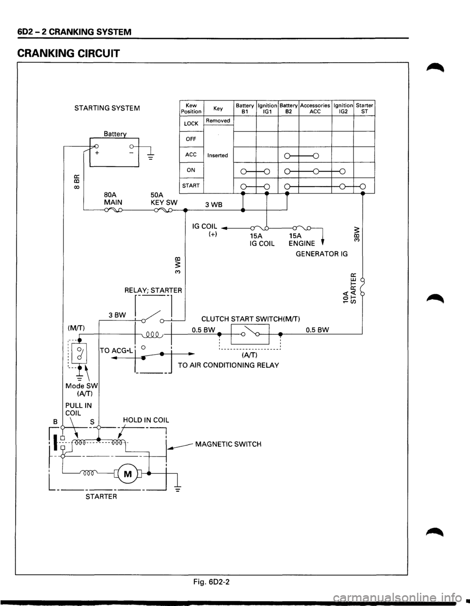
602 - 2 CRANKING SYSTEM
CRANKING CIRCUIT
STARTING SYSTEM
a: co 00
/ +
Battery
50 A
Kew
Position
LOCK
OFF
Key
Removed
ACC Inserted
ON
START Battery
Ignition Battery
Accessories Ignition Starter B1 IG1 B2 ACC IG2 ST
o----o
o----o
oc l---+----+--<0---o
BOA MAIN KEYSW 3WB I I ~~ ...;~-4:) -
IG COIL --------1~-:r uJ----a~ (+) 15A 15A IG COIL ENGINE
GENERATOR IG co :5: ('f)
RELAY; STARTER
3BW r---~
._,()-.L___j -v CLUTCH START SWITCH(M/T)
0.5
BW-I '~ I -0.5 BW ~-+-4~--~~~------~ T I ~ I T : ___________________ ~
.. (NT)
TO AIR CONDITIONING RELAY
Mode SW (NT)
PULLIN
B C\~L _S -/OLD I~ COl~
fl-~ooe--------O<>Ol -----MAGNETIC SWITCH
~-T ------+-----~.
I M
L _______ _
STARTER
Fig. 602-2
•
Page 662 of 1928
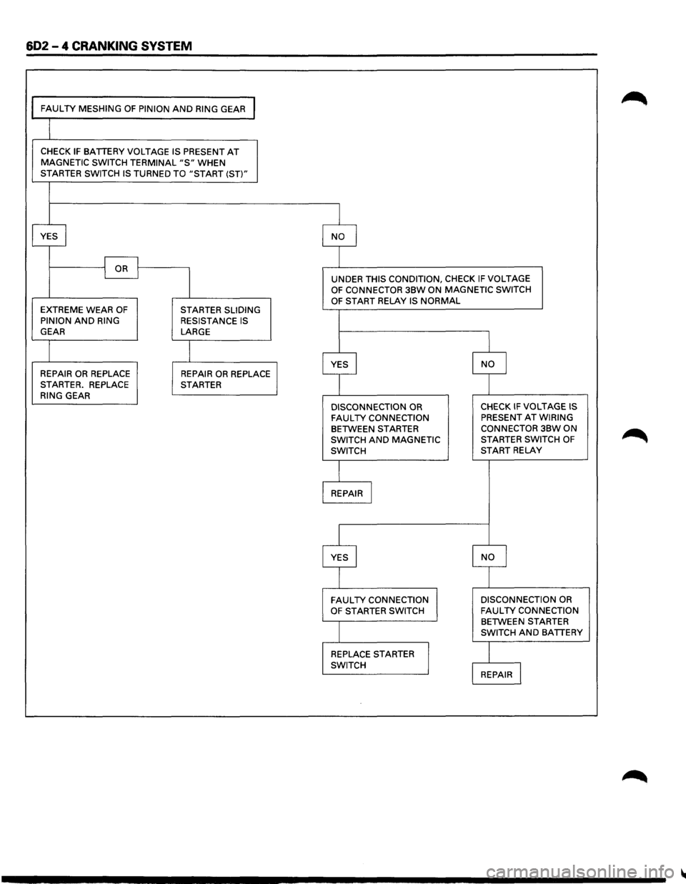
602 - 4 CRANKING SYSTEM
FAULTY MESHING OF PINION AND RING GEAR I
CHECK IF BATTERY VOLTAGE IS PRESENT AT MAGNETIC SWITCH TERMINAL "S" WHEN STARTER SWITCH IS TURNED TO "START (ST)"
YES
I NO I
I OR I I
I
UNDER THIS CONDITION, CHECK IF VOLTAGE OF CONNECTOR 3BW ON MAGNETIC SWITCH
OF START RELAY IS NORMAL EXTREME WEAR OF STARTER SLIDING
PINION AND RING RESISTANCE IS GEAR LARGE
I
I YES I NO I REPAIR OR REPLACE REPAIR OR REPLACE STARTER. REPLACE STARTER
RING GEAR
DISCONNECTION OR CHECK IF VOLTAGE IS
FAULTY CONNECTION PRESENT AT WIRING
BETWEEN STARTER
CONNECTOR 3BW ON
SWITCH
AND MAGNETIC STARTER
SWITCH OF
SWITCH START RELAY
REPAIR I
YES I NO I
FAULTY CONNECTION
DISCONNECTION OR
OF STARTER
SWITCH FAULTY CONNECTION BETWEEN STARTER
SWITCH AND BATTERY
REPLACE
STARTER
I SWITCH REPAIR l