battery ISUZU TROOPER 1995 Workshop Manual
[x] Cancel search | Manufacturer: ISUZU, Model Year: 1995, Model line: TROOPER, Model: ISUZU TROOPER 1995Pages: 1928
Page 821 of 1928
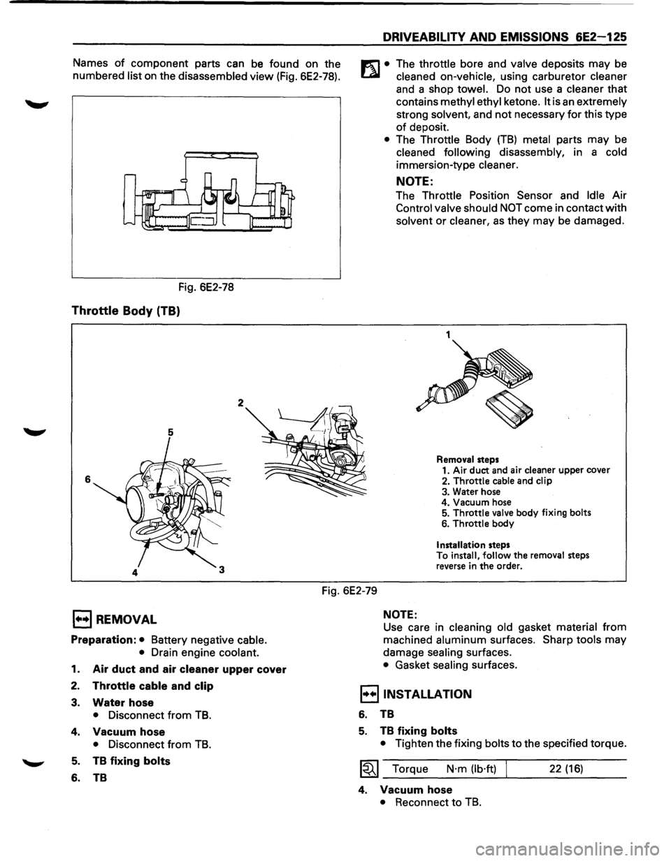
Names of component parts can be found on the
numbered
list on the disassembled view (Fig. 6E2-78).
Fig. 6E2-78
Throttle Body (TB)
5
6
2
DRIVEABILITY AND EMISSIONS 6E2-125
m • The throttle bore and valve deposits may be
t..a.l cleaned on-vehicle, using carburetor cleaner
and a shop towel. Do not use a cleaner that
contains
methyl ethyl ketone. It is an extremely
strong solvent, and
not necessary for this type
of deposit.
• The Throttle Body (TB) metal parts may be
cleaned following disassembly, in a cold
immersion-type cleaner.
NOTE:
The Throttle Position Sensor and Idle Air
Control
valve should NOT come in contact with
solvent or
cleaner, as they may be damaged.
1
Removal steps
1. Air duct and air cleaner upper cover
2.
Throttle cable and clip
3. Water hose
4. Vacuum hose
5.
Throttle valve body fixing bolts
6. Throttle body
Installation steps
To install, follow the removal steps
reverse in
the order.
Fig. 6E2-79
1••1 REMOVAL
Preparation: • Battery negative cable.
•
Drain engine coolant.
1. Air duct and air cleaner upper cover
2. Throttle cable and clip
3. Water hose
• Disconnect from TB.
4. Vacuum hose
• Disconnect from TB.
5. TB fixing bolts
6. TB
NOTE:
Use care in cleaning old gasket material from
machined
aluminum surfaces. Sharp tools may
damage
sealing surfaces.
• Gasket sealing surfaces.
I••IINSTALLATION
6. TB
5. TB fixing bolts
• Tighten the fixing bolts to the specified torque.
~~~ Torque N·m (lb·ft) 22 (16)
4. Vacuum hose
• Reconnect to TB.
Page 822 of 1928
6E2-126 DRIVEABILITV AND EMISSIONS
3. Water hoses
• Reconnect to throttle body.
2. Throttle cable and clip
1. Air duct and air cleaner upper cover
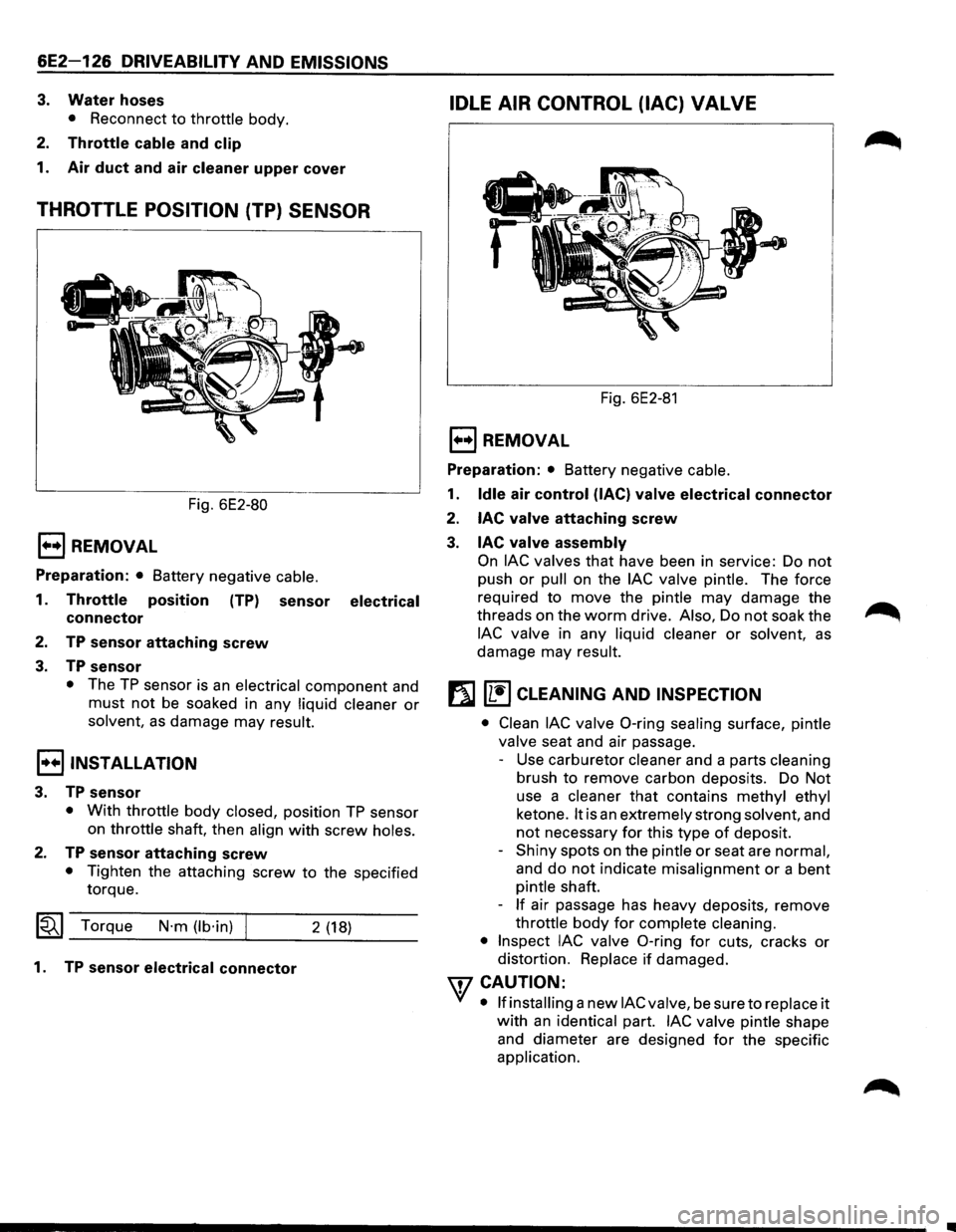
THROTTLE POSITION (TP) SENSOR
Fig. 6E2-80
1••1 REMOVAL
Preparation: • Battery negative cable.
1. Throttle position (TP) sensor electrical
connector
2. TP sensor attaching screw
3. TP sensor
• The TP sensor is an electrical component and
must not be soaked in any liquid cleaner or
solvent, as damage may result.
I••IINSTALLATION
3. TP sensor
• With throttle body closed, position TP sensor
on throttle shaft, then align
with screw holes.
2. TP sensor attaching screw
• Tighten the attaching screw to the specified
torque.
~~~ Torque N·m (lb·in) 2 (18)
1. TP sensor electrical connector
IDLE AIR CONTROL (lAC) VALVE
Fig. 6E2-81
E) REMOVAL
Preparation: • Battery negative cable.
1. Idle air control (lAC) valve electrical connector
2.
lAC valve attaching screw
3. lAC valve assembly
On lAC valves that have been in service: Do not
push or pull on the lAC valve pintle. The force
required
to move the pintle may damage the
threads on the
worm drive. Also, Do not soak the
lAC valve in any liquid cleaner or solvent, as
damage may result.
f}J [1!) CLEANING AND INSPECTION
• Clean lAC valve 0-ring sealing surface, pintle
valve seat and air passage.
- Use carburetor cleaner and a parts cleaning
brush
to remove carbon deposits. Do Not
use a cleaner
that contains methyl ethyl
ketone.
It is an extremely strong solvent, and
not necessary for this type of deposit.
-
Shiny spots on the pintle or seat are normal,
and
do not indicate misalignment or a bent
pintle shaft.
-
If air passage has heavy deposits, remove
throttle
body for complete cleaning.
• Inspect lAC valve 0-ring for cuts, cracks or
distortion. Replace
if damaged.
WCAUTION:
VI • If installing a new lAC valve, be sure to replace it
with an identical part. lAC valve pintle shape
and diameter are designed
for the specific
application.
Page 825 of 1928
DRIVEABILITY AND EMISSIONS 6E2-129
CHART C-2A
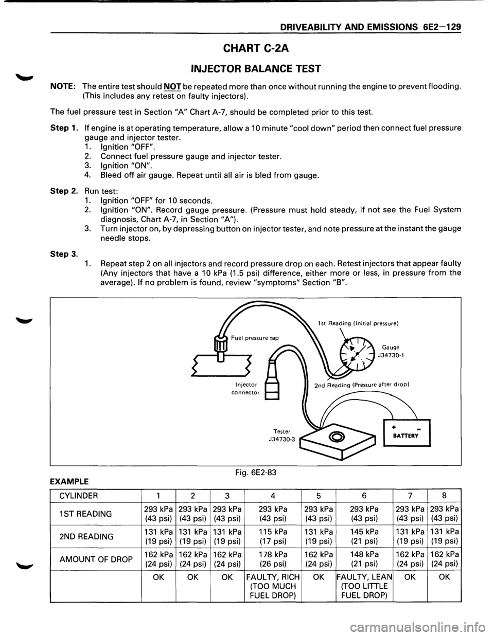
INJECTOR BALANCE TEST
NOTE: The entire test should NOT be repeated more than once without running the engine to prevent flooding.
(This includes any retest on faulty injectors).
The
fuel pressure test in Section "A" Chart A-7, should be completed prior to this test.
Step 1. If engine is at operating temperature, allow a 10 minute "cool down" period then connect fuel pressure
gauge and injector tester.
1. Ignition "OFF".
2. Connect fuel pressure gauge and injector tester.
3. Ignition "ON".
4. Bleed off air gauge. Repeat until all air is bled from gauge.
Step 2. Run test:
Step 3.
1. Ignition "OFF" for 1 0 seconds.
2. Ignition "ON". Record gauge pressure. (Pressure must hold steady, if not see the Fuel System
diagnosis, Chart A-7, in Section "A").
3. Turn injector on, by depressing button on injector tester, and note pressure at the instant the gauge
needle stops.
1. Repeat step 2 on all injectors and record pressure drop on each. Retest injectors that appear faulty
(Any injectors that have a 10 kPa (1.5 psi) difference, either more or less, in pressure from the
average).
If no problem is found, review "symptoms" Section "8".
Injector connector
Tester J34730-3
Fig. 6E2-83
Gauge J34730-1
BATTERY
EXAMPLE
CYLINDER 1 2
3 4
5 6 7 8
1ST
READING 293 kPa 293 kPa 293 kPa 293 kPa 293 kPa 293 kPa 293 kPa 293 kPa
(43 psi) (43 psi) (43 psi) (43 psi) (43 psi) (43 psi) (43 psi) (43 psi)
2ND
READING 131 kPa 131 kPa 131 kPa 115 kPa 131 kPa 145 kPa 131 kPa 131 kPa
(19 psi) (19 psi) (19 psi) (17 psi) (19 psi) (21 psi) (19 psi) (19
psi)
AMOUNT
OF DROP 162 kPa 162 kPa 162 kPa 178 kPa 162 kPa 148 kPa 162 kPa 162 kPa
(24 psi) (24 psi)
(24 psi) (26
psi) (24 psi) (21 psi) (24 psi) (24 psi)
OK OK OK FAULTY, RICH OK FAULTY, LEAN OK OK
(TOO MUCH (TOO LITTLE
FUEL DROP) FUEL DROP)
Page 829 of 1928
DRIVEABILITV AND EMISSIONS 6E2-133
CHART C-20
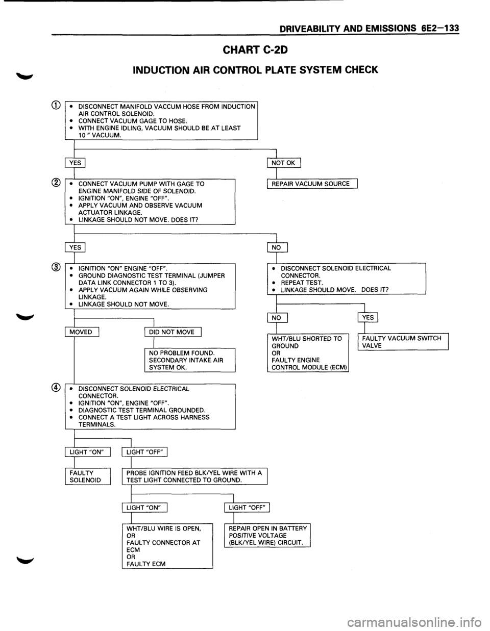
INDUCTION AIR CONTROL PLATE SYSTEM CHECK
• CONNECT VACUUM
GAGE TO HOSE.
• WITH ENGINE IDLING, VACUUM SHOULD BE AT LEAST 10" VACUUM.
~
I NOT OK I
I • CONNECT VACUUM PUMP WITH GAGE TO REPAIR VACUUM SOURCE I ENGINE MANIFOLD SIDE OF SOLENOID.
• IGNITION "ON", ENGINE "OFF".
• APPLY VACUUM AND OBSERVE VACUUM ACTUATOR LINKAGE.
• LINKAGE SHOULD NOT MOVE. DOES IT?
~ ~ • IGNITION "ON" ENGINE "OFF". • DISCONNECT SOLENOID ELECTRICAL ® • GROUND DIAGNOSTIC TEST TERMINAL (JUMPER CONNECTOR. DATA LINK CONNECTOR 1 TO 3). • REPEAT TEST. • APPLY VACUUM AGAIN WHILE OBSERVING • LINKAGE SHOULD MOVE. DOES IT?
LINKAGE.
L • LINKAGE SHOULD NOT MOVE.
~ ~ I MOVED I DID NOT MOVE I
I WHT /BLU SHORTED TO I FAULTY VACUUM SWITCH I GROUND VALVE
NO PROBLEM FOUND. OR SECONDARY INTAKE AIR FAUL TV ENGINE SYSTEM OK. CONTROL
MODULE (ECM)
• DISCONNECT SOLENOID ELECTRICAL
CONNECTOR.
• IGNITION
"ON", ENGINE "OFF".
• DIAGNOSTIC TEST TERMINAL GROUNDED. • CONNECT A TEST LIGHT ACROSS HARNESS
TERMINALS.
I LIGHT "ON" I LIGHT "OFF" I
I FAULTY
I
PROBE IGNITION FEED BLKIYEL WIRE WITH A SOLENOID TEST LIGHT CONNECTED TO GROUND.
I
l
LIGHT "ON" I LIGHT "OFF" j
I WHT/BLU WIRE IS OPEN, REPAIR OPEN IN BATTERY OR POSITIVE VOLTAGE FAUL TV CONNECTOR AT (BLKIYEL WIRE) CIRCUIT. ECM OR FAULTY ECM
Page 835 of 1928
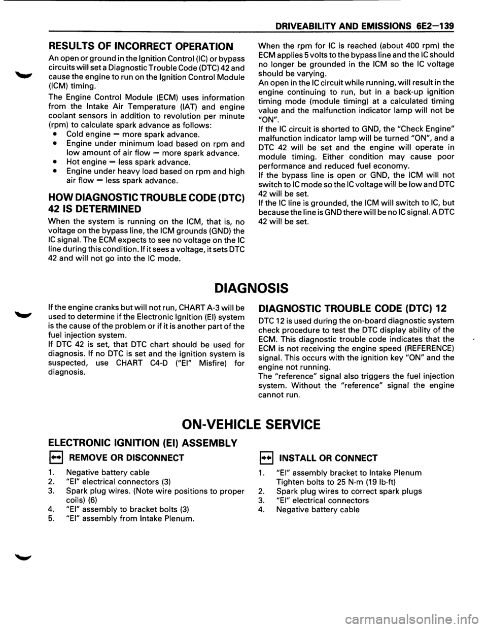
RESULTS OF INCORRECT OPERATION
An open or ground in the Ignition Control (I C) or bypass
circuits
will set a Diagnostic Trouble Code (DTC) 42 and
cause the engine
to run on the Ignition Control Module
(ICM)
timing.
The Engine
Control Module (ECM) uses information
from the Intake Air Temperature (IAT) and engine
coolant sensors in addition to revolution per minute
(rpm) to
calculate spark advance as follows:
• Cold
engine -more spark advance.
• Engine under minimum load based on rpm and
low amount of air flow = more spark advance.
• Hot engine = less spark advance.
• Engine under heavy load based on rpm and high
air
flow = less spark advance.
HOW DIAGNOSTIC TROUBLE CODE (DTC)
42 IS DETERMINED
When the system is running on the ICM, that is, no
voltage on the bypass line, the ICM grounds (GND) the
IC signal. The ECM expects to see no voltage on the IC
line during this condition.lf it sees a voltage, it sets DTC
42 and will not go into the IC mode.
DRIVEABILITY AND EMISSIONS 6E2-139
When the rpm for IC is reached (about 400 rpm) the
ECM applies 5 volts to the bypass line and the IC should
no longer be grounded in the ICM so the IC voltage
should
be varying.
An open in the
IC circuit while running, will result in the
engine continuing to run, but in a back-up
ig~it~on
timing mode (module timing) at a calculated t1mmg
value
and the malfunction indicator lamp will not be
"ON".
If
the IC circuit is shorted to GND, the "Check Engine"
malfunction
indicator lamp will be turned "ON", and a
DTC 42 will be set and the engine will operate in
module timing. Either condition may cause poor
performance and reduced
fuel economy.
If the bypass line is open or GND, the ICM will not
switch to IC mode so the IC voltage will be low and DTC
42 will be set.
If the IC line is grounded, the ICM will switch to IC, but
because the line isGNDtherewill be no ICsignai.A DTC
42 will be set.
DIAGNOSIS
If the engine cranks but will not run, CHART A-3 will be
used to determine if the Electronic Ignition (EI) system
is the cause
of the problem or if it is another part of the
fuel injection system.
If DTC 42 is set, that DTC chart should be used for
diagnosis. If no DTC is set and the ignition system is
suspected, use
CHART C4-D ("EI" Misfire) for
diagnosis.
DIAGNOSTIC TROUBLE CODE (DTC) 12
DTC 12 is used during the on-board diagnostic system
check procedure to test the
DTC display ability of the
ECM. This diagnostic trouble code indicates that the
ECM is not receiving the engine speed (REFERENCE)
signal. This occurs with the ignition key "ON" and the
engine not running.
The "reference"
signal also triggers the fuel injection
system.
Without the "reference" signal the engine
cannot run.
ON-VEHICLE SERVICE
ELECTRONIC IGNITION (EI) ASSEMBLY
1••1 REMOVE OR DISCONNECT
1. Negative battery cable
2. "EI" electrical connectors (3)
3. Spark plug wires. (Note wire positions to proper
coils) (6)
4. "EI" assembly to bracket bolts (3)
5. "EI" assembly from Intake Plenum.
1••1 INSTALL OR CONNECT
1. "EI" assembly bracket to Intake Plenum
Tighten bolts to 25 N·m (19 lb·ft)
2. Spark plug wires to correct spark plugs
3. "EI" electrical connectors
4. Negative battery cable
Page 836 of 1928
6E2-140 DRIVEABILITY AND EMISSIONS
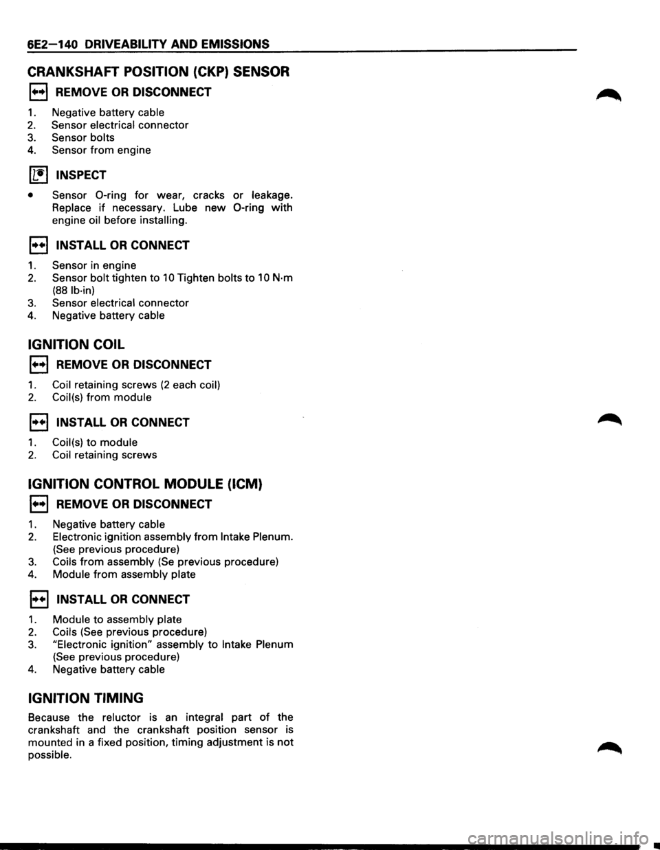
CRANKSHAFT POSITION (CKP) SENSOR
1••1 REMOVE OR DISCONNECT
1. Negative battery cable
2. Sensor electrical connector
3. Sensor bolts
4. Sensor from engine
11!) INSPECT
• Sensor 0-ring for wear, cracks or leakage.
Replace
if necessary. Lube new 0-ring with
engine oil before installing.
1••1 INSTALL OR CONNECT
1. Sensor in engine
2. Sensor bolt tighten to 10 Tighten bolts to 10 N·m
(88 lb·in)
3. Sensor electrical connector
4. Negative battery cable
IGNITION COIL
1••1 REMOVE OR DISCONNECT
1. Coil retaining screws (2 each coil)
2. Coil(s) from module
1••1 INSTALL OR CONNECT
1. Coil(s) to module
2. Coil retaining screws
IGNITION CONTROL MODULE (ICM)
1••1 REMOVE OR DISCONNECT
1. Negative battery cable
2. Electronic ignition assembly from Intake Plenum.
(See previous procedure)
3. Coils from assembly (Se previous procedure)
4. Module from assembly plate
1••1 INSTALL OR CONNECT
1. Module to assembly plate
2. Coils (See previous procedure)
3. "Electronic ignition" assembly to Intake Plenum
(See previous procedure)
4. Negative battery cable
IGNITION TIMING
Because the reluctor is an integral part of the
crankshaft and the crankshaft position sensor is
mounted in a fixed position,
timing adjustment is not
possible .
........................................................................\
........ ;; .
Page 843 of 1928
DRIVEABILITY AND EMISSIONS 6E2-147
ON-VEHICLE SERVICE
KNOCK SENSOR (KS) SYSTEM
Refer to engine section of this service manual for intake
removal and access to the knock sensor (KS).
KNOCK SENSOR (KS) MODULE
Refer to (Figure C5-1).
KS module is mounted to a bracket, located at the
upper right hand corner
of the inner fender.
1••1 REMOVE OR DISCONNECT
1. Negative battery cable
2. KS module connector
3. Attaching screws
4. Evaporate emission canister purge bracket
5. KS module
1••1 INSTALL OR CONNECT
1. KS module
2. Attaching screws
3. KS module connector
4. Evaporate emission canister purge bracket
5. Negative battery cable
Page 858 of 1928
6E2-162 DRIVEABILITY AND EMISSIONS
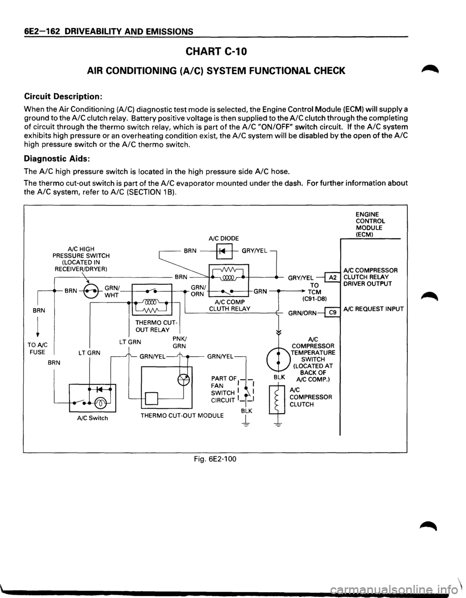
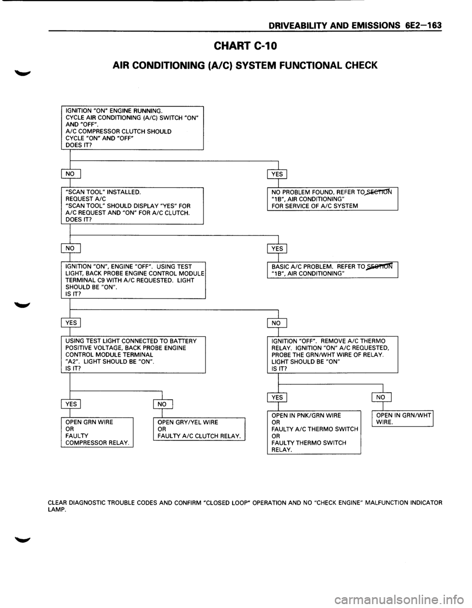
CHART C-10
AIR CONDITIONING (A/C) SYSTEM FUNCTIONAL CHECK
Circuit Description:
When the Air Conditioning (A/C) diagnostic test mode is selected, the Engine Control Module (ECM) will supply a
ground to the
A/C clutch relay. Battery positive voltage is then supplied to the A/C clutch through the completing
of circuit through the thermo switch relay, which is part of the A/C "ON/OFF" switch circuit. If the A/C system
exhibits high pressure or
an overheating condition exist, the A/C system will be disabled by the open of the A/C
high pressure switch or the A/C thermo switch.
Diagnostic Aids:
The A/C high pressure switch is located in the high pressure side A/C hose.
The
thermo cut-out switch is part of the A/C evaporator mounted under the dash. For further information about
the
A/C system, refer to A/C (SECTION 1 8).
BRN
TONC FUSE
NC HIGH
PRESSURE SWITCH
(LOCATED IN
RECEIVER/DRYER)
LTGRN
BRN
NC Switch
NC DIODE
BRN a GRY!YEL
THERMO CUTOUT RELAY
LTGRN PNK/ GRN
NCCOMP CLUTH RELAY
PARTOF1-FAN I SWITCH I I CIRCUIT I __ I
BLK THERMO CUT-OUT MODULE j_
Fig. 6E2-100
ENGINE
CONTROL
MODULE (ECM)
NC COMPRESSOR CLUTCH RELAY DRIVER OUTPUT
NC REQUEST INPUT
Page 859 of 1928
DRIVEABILITV AND EMISSIONS 6E2-163
CHART C-10
AIR CONDITIONING (A/C) SYSTEM FUNCTIONAL CHECK
IGNITION "ON" ENGINE RUNNING.
CYCLE AIR CONDITIONING (A/C) SWITCH "ON" AND "OFF". A/C COMPRESSOR CLUTCH SHOULD
CYCLE "ON" AND "OFF"
DOES IT?
$
$
"SCAN TOOL" INSTALLED.
NO PROBLEM FOUND, REFER TO)>e€TIO'N REQUEST A/C "1B", AIR CONDITIONING"
"SCAN TOOL" SHOULD DISPLAY "YES" FOR FOR SERVICE OF A/C SYSTEM A/C REQUEST AND "ON" FOR A/C CLUTCH.
DOES IT?
$
$
IGNITION "ON", ENGINE "OFF". USING TEST BASIC A/C PROBLEM. REFER TO~ LIGHT, BACK PROBE ENGINE CONTROL MODULE "1B", AIR CONDITIONING"
TERMINAL C9 WITH A/C REQUESTED. LIGHT
SHOULD BE "ON". IS IT?
$ $
USING TEST LIGHT CONNECTED TO BATTERY IGNITION "OFF". REMOVE A/C THERMO
POSITIVE VOLTAGE, BACK PROBE ENGINE RELAY. IGNITION "ON" A/C REQUESTED, CONTROL MODULE TERMINAL PROBE THE GRN/WHT WIRE OF RELAY. "A2". LIGHT SHOULD BE "ON". LIGHT SHOULD BE "ON" IS IT?
IS IT?
I
$ $
~ $ OPEN IN PNK/GRN WIRE I OPEN IN GRN/WHTJ OPEN GRN WIRE
OPEN GRY/YEL WIRE OR WIRE. OR OR FAULTY A/C THERMO SWITCH FAULTY FAULTY A/C CLUTCH RELAY. OR COMPRESSOR RELAY. FAULTY THERMO SWITCH RELAY.
CLEAR DIAGNOSTIC TROUBLE CODES AND CONFIRM "CLOSED LOOP" OPERATION AND NO "CHECK ENGINE" MALFUNCTION INDICATOR LAMP.
Page 865 of 1928
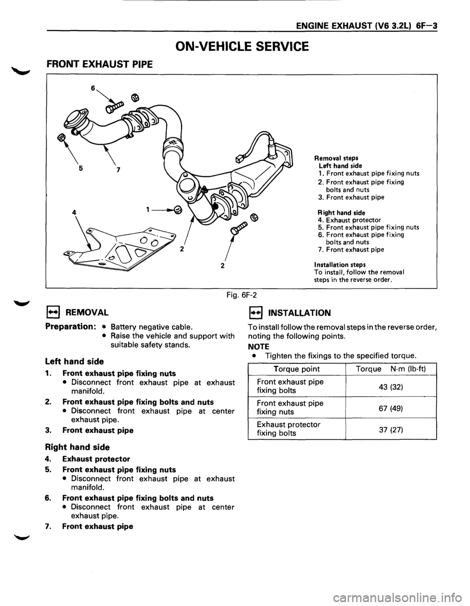
ENGINE EXHAUST (V6 3.2L) &F-3
ON-VEHICLE SERVICE
FRONT EXHAUST PIPE
2
Removal steps
Left hand side
1.
Front exhaust pipe fixing nuts
2. Front exhaust pipe fixing
bolts and nuts
3. Front exhaust pipe
Right hand side
4. Exhaust
protector 5. Front exhaust pipe fixing nuts 6. Front exhaust pipe fixing bolts and nuts
7. Front exhaust pipe
Installation steps
To install, follow the removal steps in the reverse order.
Fig. 6F-2
EJ REMOVAL
Preparation: • Battery negative cable.
•
Raise the vehicle and support with
suitable safety stands.
Left hand side
1. Front exhaust pipe fixing nuts
• Disconnect front exhaust pipe at exhaust
manifold.
2. Front exhaust pipe fixing bolts and nuts
• Disconnect front exhaust pipe at center
exhaust pipe.
3.
Front exhaust pipe
Right hand side
4. Exhaust protector
5. Front exhaust pipe fixing nuts
• Disconnect front exhaust pipe at exhaust
manifold.
6. Front exhaust pipe fixing bolts and nuts
• Disconnect front exhaust pipe at center
exhaust pipe.
1. Front exhaust pipe
1•+1 INSTALLATION
To install follow the removal steps in the reverse order,
noting the
following points.
NOTE
• Tighten the fixings to the specified torque.
Torque point Torque
N·m (lb·ft)
Front exhaust pipe
43 (32) fixing bolts
Front exhaust pipe 67 (49) fixing nuts
Exhaust protector
37 (27) fixing bolts