battery ISUZU TROOPER 1995 Workshop Manual
[x] Cancel search | Manufacturer: ISUZU, Model Year: 1995, Model line: TROOPER, Model: ISUZU TROOPER 1995Pages: 1928
Page 926 of 1928
7A-54 AUTOMATIC TRANSMISSION (4L30-E)
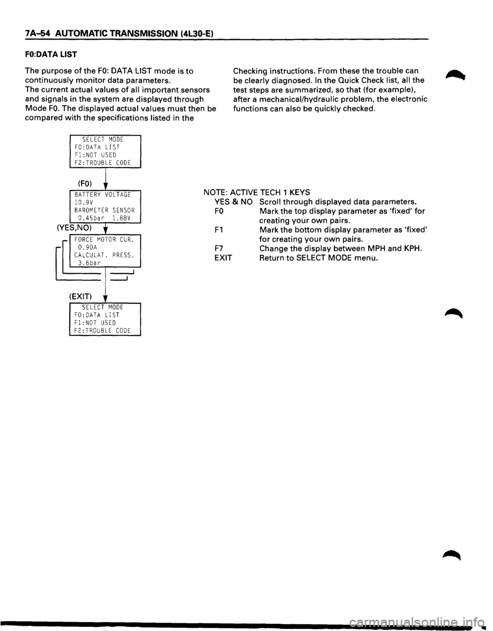
FO:DATA LIST
The purpose of the FO: DATA LIST mode is to
continuously monitor data parameters.
The current actual values
of all important sensors
and signals in the system are displayed
through
Mode FO. The displayed actual values must then be
compared
with the specifications listed in the
SELECT MODE
FO: DATA LIST Fl:NOT USED F2:TROUBLE CODE
(FO) r
Checking instructions. From these the trouble can
be clearly diagnosed.
In the Quick Check list, all the
test steps are summarized, so
that (for example),
after a mechanical/hydraulic problem, the electronic
functions can also be quickly checked.
BATTERY VOLTAGE NOTE: ACTIVE TECH 1 KEYS
10.9V BAROMETER SENSOR 0.45bar 1. 88V
(YES,NO)
' r FORCE MOTOR CUR.
-0.90A CALCULAT. PRESS. 3.6bar
_....J
---'
(EXIT)
SELECT MODE FO:DATA LIST Fl:NOT USED F2:TROUBLE CODE
YES & NO Scroll through displayed data parameters.
FO Mark the top display parameter as 'fixed' for
F1
F7
EXIT
creating your own pairs.
Mark the bottom display parameter as 'fixed'
for creating your own pairs.
Change the display between MPH and
KPH.
Return to SELECT MODE menu.
Page 929 of 1928
AUTOMATIC TRANSMISSION (4l30·E) 7 A-57
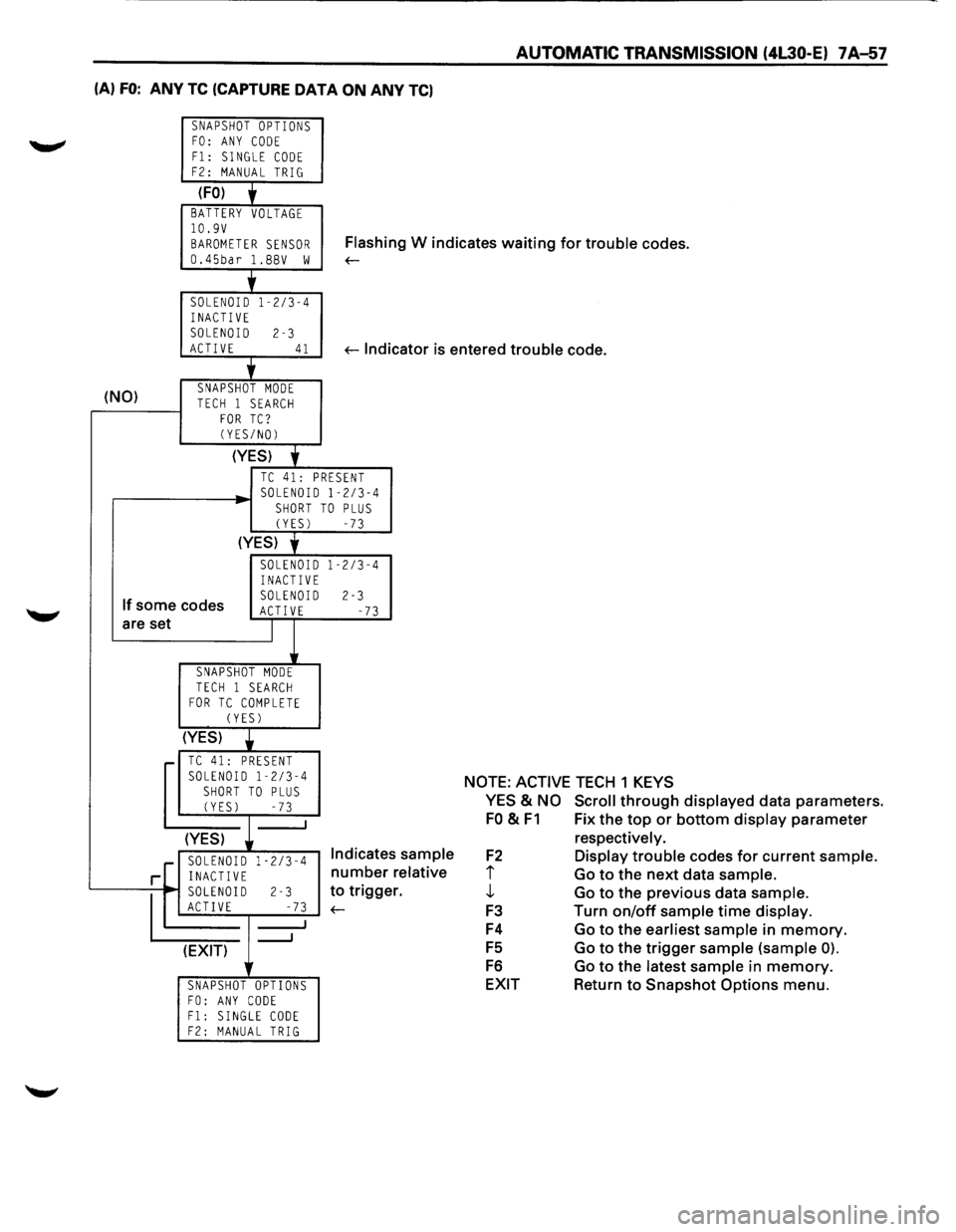
(A) FO: ANY TC (CAPTURE DATA ON ANY TC)
SNAPSHOT OPTIONS FO: ANY CODE
F1: SINGLE CODE F2: MANUAL TRIG
(FO) + BATTERY VOLTAGE 10.9V
BAROMETER SENSOR Flash in g W indicates waiting for trouble codes.
0.45bar l.BBV w ~
'
SOLENOID 1-2/3-4
INACTIVE SOLENOID 2-3 ACTIVE 41 ~lndi cator is entered trouble code.
+
(NO) SNAPSHOT MODE TECH 1 SEARCH FOR TC? (YES/NO)
(YES)
'
TC 41: PRESENT SOLENOID 1-2/3-4 SHORT TO PLUS (YES) -73
(YES) y
SOLENOID 1-2/3-4 INACTIVE
If some codes SOLENOID 2-3 ACT! VE -73 are set I
SNAPSHOT MODE
TECH 1 SEARCH FOR TC COMPLETE (YES)
(YES)
• TC 41: PRESENT SOLENOID 1-2/3-4
SHORT TO PLUS (YES) -73
(YES)
.[ SOLENOID 1-2/3-4 Indicates sample
relative
r. r INACTIVE number
~0
2-3 to trigge
E -73 ~
_J (EXIT) lr
SNAPSHOT OPTIONS FO: ANY CODE F1: SINGLE CODE F2: MANUAL TRIG
NOTE: ACTIVE TECH 1 KEYS
YES
& NO Scroll through displayed data parameters.
FO & F1 Fix the top or bottom display parameter
F2
i j,
F3
F4
FS
F6
EXIT respectively.
Display trouble
codes for current sample.
Go to the next data sample.
Go to the previous data sample.
Turn on/off sample time display.
Go to the earliest sample in memory.
Go to the trigger sample (sample 0).
Go to the latest sample in memory.
Return to Snapshot Options menu.
Page 931 of 1928
AUTOMATIC TRANSMISSION (4l30-E) 7A-59
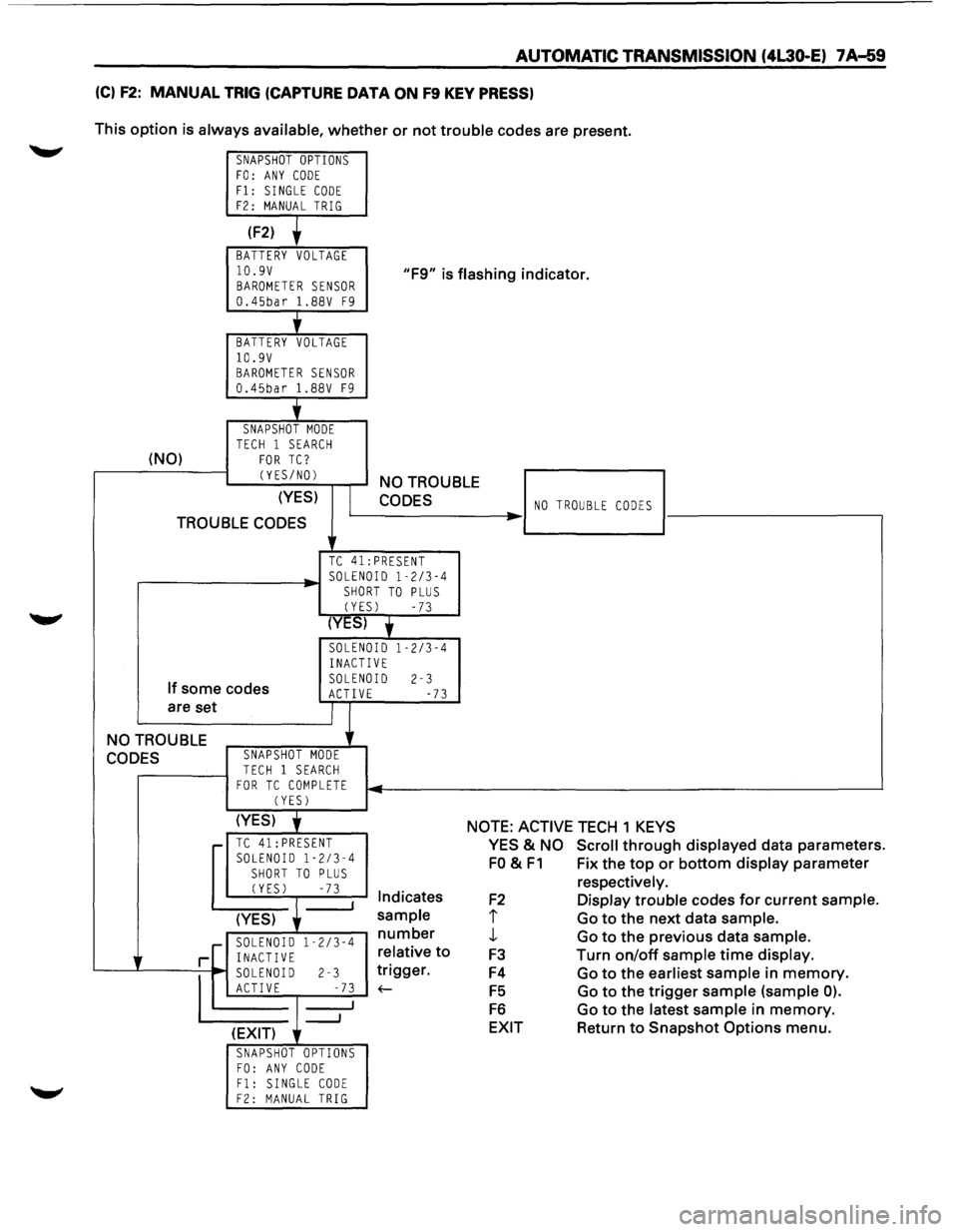
(C) F2: MANUAL TRIG (CAPTURE DATA ON F9 KEY PRESS)
This option is always available, whether or not trouble codes are present.
SNAPSHOT OPTIONS FO: ANY CODE Fl: SINGLE CODE F2: MANUAL TRIG
(F2)
BATTERY VOLTAGE
10.9V BAROMETER SENSOR 0.45bar 1.88V F9
"F9" is flashing indicator.
'
BATTERY VOLTAGE 10.9V BAROMETER SENSOR 0.45bar 1.88V F9
j_
SNAPSHOT MODE TECH 1 SEARCH (NO) FOR TC?
CYES/NOl
(YES)
TROUBLE CODES
NO TROUBLE
CODES
TC 41:PRESENT
.----------~· SOLENOID 1-2/3-4 SHORT TO PLUS
CYESl -73
(YES) y
SOLENOID 1-2/3-4
INACTIVE
If some codes
are set SOLENOID 2-3 ACTIVE -73
NO TROUBLE
CODES SNAPSHOT MODE
TECH 1 SEARCH FOR TC COMPLETE CYESl
NO TROUBLE CODES ..
(YES) j NOTE: ACTIVE TECH 1 KEYS r-TC 41: PRESENT SOLENOID 1-2/3-4
SHORT TO PLUS CYESl -73 I Indicates
(YES)
sample
r--~~:--":'"~~ number
r[ i~~g~0~ 1 -2
/3
-4 relative
to
'---...L----=--
1
~ soLEN~ I-D r-------l-2 _-~...;.7.;;..3 1
__, ~gger.
(EXIT)
SNAPSHOT OPTIONS FO: ANY CODE Fl: SINGLE CODE F2: MANUAL TRIG
YES & NO Scroll through displayed data parameters.
FO & F1 Fix the top or bottom display parameter
F2
I
J,
F3
F4
F5
F6
EXIT
respectively.
Display trouble codes for current sample.
Go to the next data sample.
Go to the previous data sample.
Turn
on/off sample time display.
Go to the earliest sample in memory.
Go to the trigger sample (sample 0).
Go to the latest sample in memory.
Return to Snapshot Options menu.
Page 941 of 1928
AUTOMATIC TRANSMISSION (4L30-E) 7 A-69
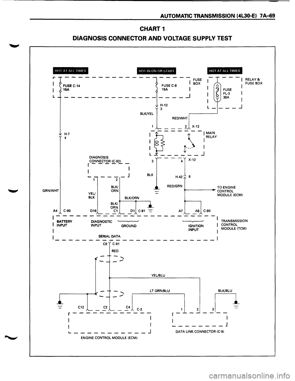
CHART 1
DIAGNOSIS CONNECTOR AND VOLTAGE SUPPLY TEST
HOf AT All TIMES
r
L
GRN/WHT
FUSE C-14 15A
H-7 4
A4 C-90 DIAGNOSIS
CONNECTOR
(C-92) r------
1 I
----J 2
BLKI ORN
HOT IN ON OR START
FUSE C-8
15A I
I
__ _I
FUSE BOX
HOT AT ALL TIMES
---
l
A FUSE FL-3 30A
I I
I
I
H-13
BLKJYEL
1
[_ --
RED/WHT
L-___ _j
2
X-12
:1?.---- -:~t~v
I }-I t·---I L _______ _j
---r-12
H-42/o 8
3
BLK
RED/GRN
""--------i~ TO ENGINE
..- CONTROL
MODULE
(ECM)
YELl
BLK BLK!ORN
D16
BLKI
ORN
Cl Dl C-91 A7 AS C-90
RELAY& FUSE BOX
~------------------------BATTERY DIAGNOSTIC · · I
I INPUT INPUT GROUND IGNITION I
I INPUT I
TRANSMISSION
CONTROL MODULE
(TCM)
I SERIAL DATA
------------------------1 CB C-91
RED
YEL/BLU
L T GRN/BLU BLKIBLU
,_1_, ~n
I I ________ J
C12 C-2 r------------
1 I
I I
1...--------_J DATA LINK CONNECTOR (C-9)
ENGINE CONTROL MODULE (ECM)
Page 942 of 1928
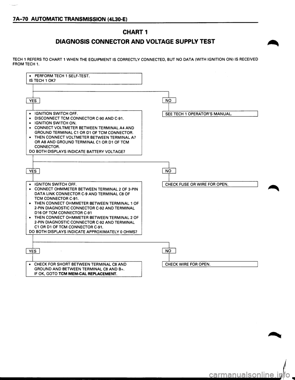
7A-70 AUTOMATIC TRANSMISSION (4L30-E)
CHART 1
DIAGNOSIS CONNECTOR AND VOLTAGE SUPPLY TEST
TECH 1 REFERS TO CHART 1 WHEN THE EQUIPMENT IS CORRECTLY CONNECTED, BUT NO DATA (WITH IGNITION ON) IS RECEIVED
FROM TECH 1.
• PERFORM TECH 1 SELF-TEST . IS TECH 1 OK?
~ ~
• IGNITION SWITCH OFF . I SEE TECH 1 OPERATOR'S MANUAL. I • DISCONNECT TCM CONNECTOR C-90 AND C-91 .
• IGNITION SWITCH ON .
• CONNECT VOLTMETER BETWEEN TERMINAL A4 AND GROUND TERMINAL C1 OR D1 OF TCM CONNECTOR.
•
THEN CONNECT VOLTMETER BETWEEN TERMINAL A7 OR AS AND GROUND TERMINAL C1 OR D1 OF TCM
CONNECTOR.
DO BOTH DISPLAYS INDICATE
BATTERY VOLTAGE?
+ ~ • IGNITON SWITCH OFF. I CHECK FUSE OR WIRE FOR OPEN. I • CONNECT OHMMETER BETWEEN TERMINAL 2 OF 3-PIN DATA LINK CONNECTOR C-9 AND TERMINAL CS OF
TCM CONNECTOR C-91.
•
THEN CONNECT OHMMETER BETWEEN TERMINAL 1 OF
2-PIN DIAGNOSTIC CONNECTOR C-92 AND TERMINAL D16 OF TCM CONNECTOR C-91
• THEN CONNECT OHMMETER BETWEEN TERMINAL 2 OF 2-PIN DIAGNOSTIC CONNECTOR C-92 AND TERMINAL C1 OR D1 OF TCM CONNECTOR C-91.
DO BOTH DISPLAYS INDICATE APPROXIMATELY 0 OHMS?
~ ~ • CHECK FOR SHORT BETWEEN TERMINAL CS AND I CHECK WIRE FOR OPEN. I GROUND AND BETWEEN TERMINAL CS AND B+. IF OK, GOTO TCM MEM-CAL REPLACEMENT.
____________ _,,(
Page 962 of 1928
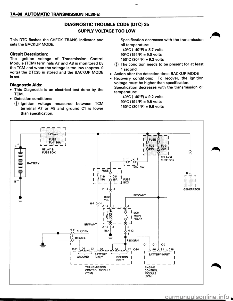
7 A-90 AUTOMATIC TRANSMISSION (4L30-E)
DIAGNOSTIC TROUBLE CODE (DTC) 25
SUPPLY VOLTAGE TOO LOW
This DTC flashes the CHECK TRANS indicator and
sets the BACKUP
MODE.
Specification decreases with the transmission
oil temperature:
Circuit Description:
-40°C (-40°F) = S.7 volts
90°C (194°F) = 9.0 volts
150°C (304°F) = 9.2 volts The ignition voltage of Transmission Control
Module (TCM) terminals A7 and AS is monitored by
the TCM and when the voltage is too low (approx. 9
volts) the DTC25 is stored and the BACKUP MODE
is set.
@ The condition needs to be present for at least
1 second
• Action after the detection time: BACKUP MODE
Diagnostic Aids:
• This Diagnostic is an electrical test done by the
TCM.
• Recovery conditions: To recover, the ignition
voltage must be higher than specification.
Specification decreases
with the transmission oil
temperature:
-40°C (-40°F) = 9.2 volts
90°C (194°F) = 9.5 volts
150°C (304°F) = 9.6 volts
• Detection conditions:
CD Ignition voltage measured between TCM
terminal A7 or AS and ground C1 is lower
than specification .
. · fU I
I '
f:L;~soA L., ____ J
RELAY & FUSE BOX
1--, {)-:,.--____..J BATTERY
l
T
L __ I
r
I C-14 C-8 I I 15A 15A FUSE -__ + _ j BOX
H-13t 3
H-7 'x~.~~'---7 r ]_-
GRN/WHT
BATTERY I GROUND INPUT IGNITION I INPUT I
L-----------TRANSMISSION
CONTROL MODULE
(TCM) IGN.SW.
RED/WHT
C-1 C-1 C-2
A6 B1 C16
r -;ATTERV INPUT-l
I
I l _____ j
ENGINE
CONTROL MODULE
(ECM)
I I
I-_j GENERATOR
Page 963 of 1928
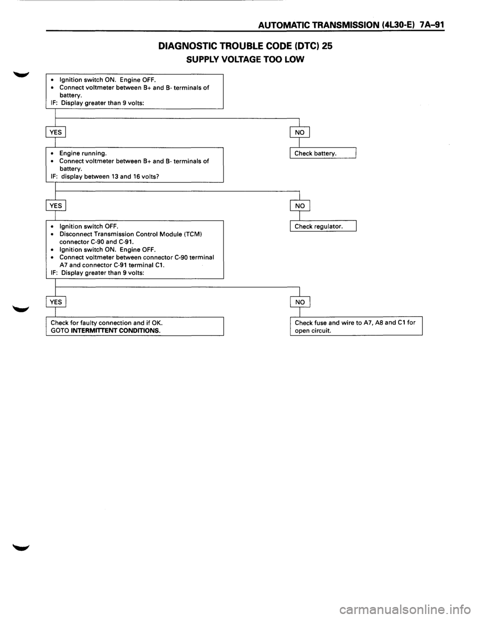
AUTOMATIC TRANSMISSION (4L30-E) 7A-91
DIAGNOSTIC TROUBLE CODE (DTC) 25
SUPPLY VOLTAGE TOO LOW
• Ignition switch ON. Engine OFF.
• Connect voltmeter between B+ and B-terminals of battery. IF: Display greater than 9 volts:
•
Engine running.
• Connect voltmeter between B+ and B-terminals of battery.
IF: display between 13 and 16 volts?
• Ignition
switch OFF. • Disconnect Transmission Control Module (TCM)
connector C-90 and C-91. • Ignition switch ON. Engine OFF.
• Connect voltmeter between connector C-90 terminal A7 and connector C-91 terminal C1. IF: Display greater than 9 volts:
Check for faulty connection and if OK.
GOTO INTERMITTENT CONDITIONS.
Check fuse and wire to A7, AS and C1 for
open circuit.
Page 964 of 1928
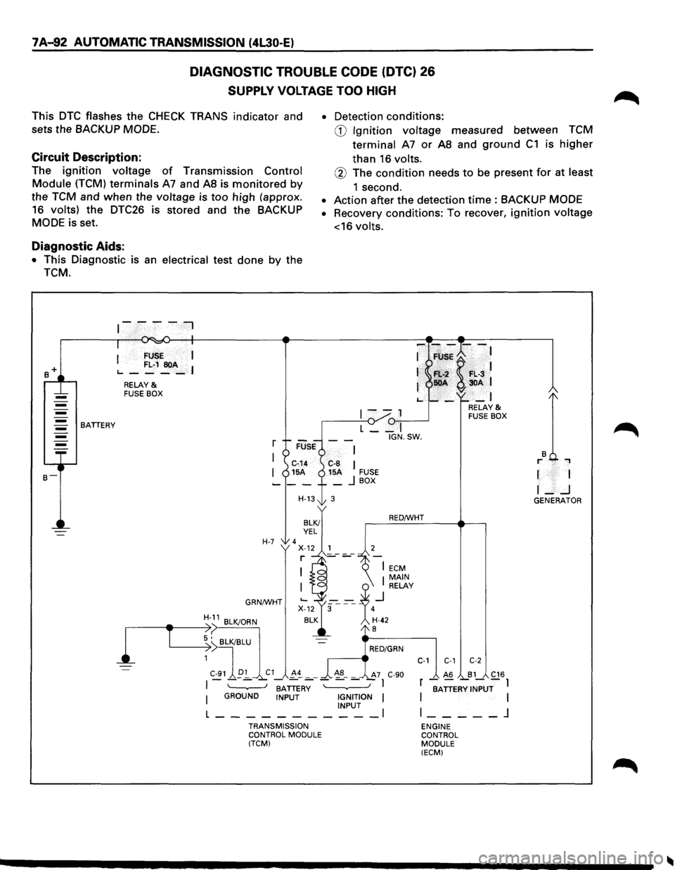
7 A-92 AUTOMATIC TRANSMISSION (4L30-E)
DIAGNOSTIC TROUBLE CODE (DTC) 26
SUPPLY VOLTAGE TOO HIGH
This DTC flashes the CHECK TRANS indicator and
sets the
BACKUP MODE.
Circuit Description:
The ignition voltage of Transmission Control
Module (TCM) terminals A7 and AS is monitored by
the TCM and when the voltage is too high (approx.
16 volts) the
DTC26 is stored and the BACKUP
MODE is set.
Diagnostic Aids:
• This Diagnostic is an electrical test done by the
TCM.
BATTERY
I FUSE I
L..-FL·1~A-I
RELAY & FUSE BOX
r
I
I
H-7
GRN/WHT
H-11 BLK/ORN
• Detection conditions:
CD Ignition voltage measured between TCM
terminal
A7 or AS and ground C1 is higher
than 16 volts.
® The condition needs to be present for at least
1 second.
• Action after the detection time : BACKUP MODE
• Recovery conditions: To recover, ignition voltage
<16
volts.
-F~;K--:
Fl:.-2 F•. L·3 50A 3DA 1
-_I
1--1 (1-,,--...----J L __ I
IGN.SW.
C-8 I 15A FUSE _ j BOX
3
RED/WHT
RELAY & FUSE BOX
r 1
I-..J GENERATOR
1
,-----------e-T ~:>( BLK/BLU
~ I RED/GRN
1
C-91 ~p:!_ C1 !-~ _ _ ~8-_ A7 C-90
C-1 C-1 C-2
I - - - -BATTER~ - - - -I
I GROUND INPUT IGNITION I INPUT l ___________ l
TRANSMISSION
CONTROL MODULE
(TCM)
_ A6 _B1_ C16
r BATTERY INPUT I I I
l _____ j
ENGINE
CONTROL
MODULE (ECM)
Page 965 of 1928
AUTOMATIC TRANSMISSION (4l30·E) 7 A-93
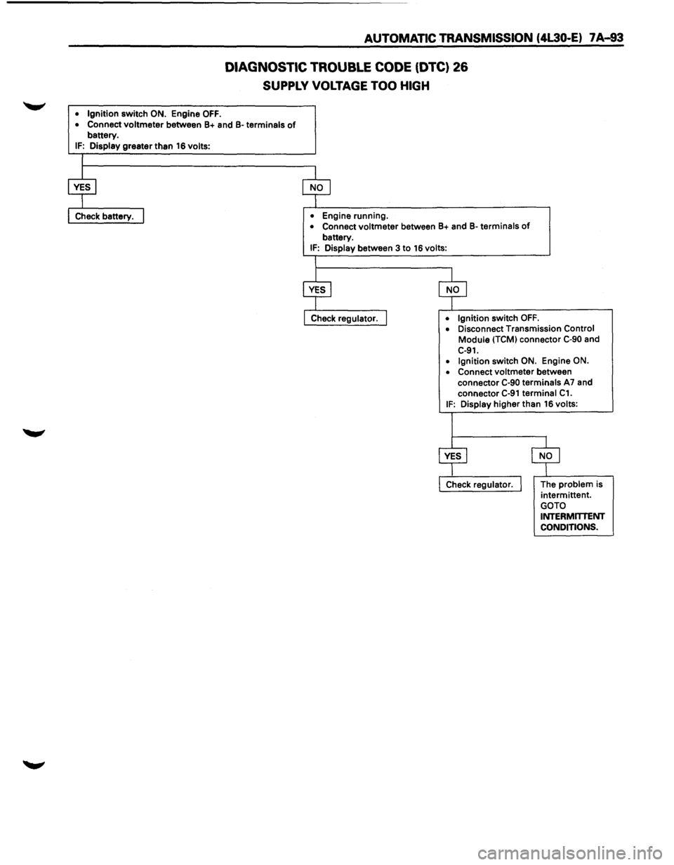
DIAGNOSTIC TROUBLE CODE (DTC) 26
SUPPLY VOLTAGE TOO HIGH
• Ignition switch ON. Engine OFF.
• Connect voltmeter between B+ and B-terminals of battery. IF: Display greater than 16 volts:
•
Engine running. • Connect voltmeter between B+ and B-terminals of
battery. IF: Display between 3 to 16 volts:
• Ignition
switch OFF. • Disconnect Transmission Control
Module (TCM) connector C-90 and
C-91. • Ignition switch ON. Engine ON.
•
Connect voltmeter between
connector C-90 terminals A7 and
connector C-91 terminal C1. IF: Display higher than 16 volts:
Check regulator. The problem is
intermittent.
GOTO
INTERMITIENT CONDITIONS.
Page 980 of 1928
7A-108 AUTOMATIC TRANSMISSION (4l30·E)
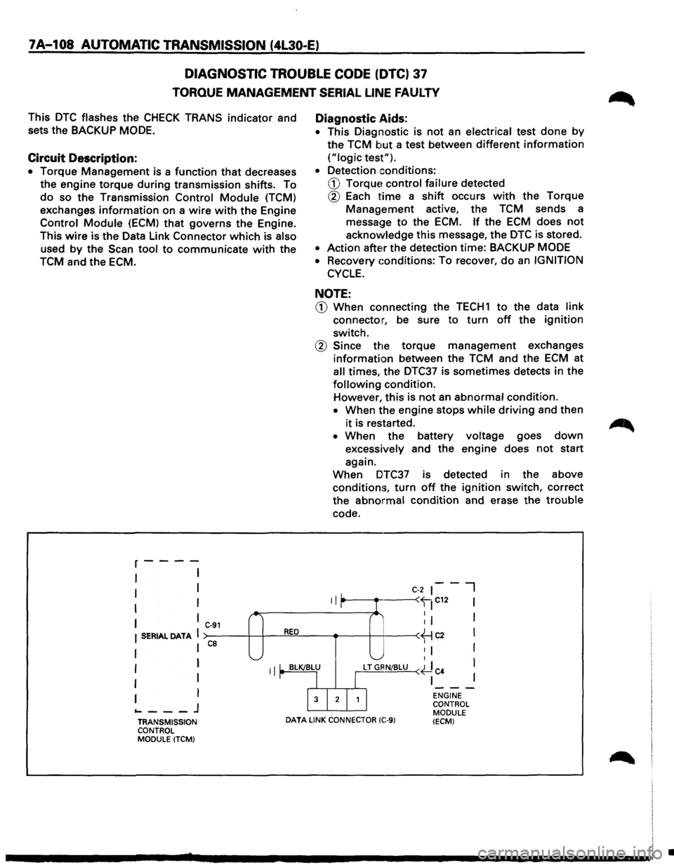
DIAGNOSTIC TROUBLE CODE (DTC) 37
TORQUE MANAGEMENT SERIAL LINE FAULTY
This DTC flashes the CHECK TRANS indicator and
sets the
BACKUP MODE.
Circuit Description:
• Torque Management is a function that decreases
the engine
torque during transmission shifts. To
do so the Transmission Control Module (TCM)
exchanges
information on a wire with the Engine
Control Module (ECM) that governs the Engine.
This
wire is the Data Link Connector which is also
used by the Scan tool to communicate with the
TCM and the ECM.
r----
I I
I I
I I
I ,_
I C-91
I SERIAL DATA I RED
ca
I I '-._....;
Diagnostic .Aids:
• This
Diagnostic is not an electrical test done by
the TCM but a test between different information
("logic test").
•
Detection conditions:
CD Torque~ control failure detected
® Each time a shift occurs with the Torque
Management active, the TCM sends a
message
to the ECM. If the ECM does not
acknowledge this message, the DTC is stored.
• Action after the detection time: BACKUP MODE
• Recovery Gonditions: To recover, do an IGNITION
CYCLE.
NOTE:
CD When connecting the TECH1 to the data link
connector, be sure to turn off the ignition
switch.
® Since the torque management exchanges
information between the TCM and the ECM at
all times, the DTC37 is sometimes detects in the
following condition.
However,
this is not an abnormal condition.
• When the engine stops while driving and then
it is restarted.
• When the battery voltage goes down
excessively and the engine does not start
again.
When DTC37 is detected in the above
conditions,
turn off the ignition switch, correct
the
abnormal condition and erase the trouble
code.
II L
C-2 ~--I
r I ----
I I I '-" t
I I II' BLK/BLU
LT GRN/BLU (~ C
4 I
I I
r I I
I
I
I 3 I 2 I 1 I
---I ENGINE
... ---J CONTROL
MODULE
TRANSMISSION
DATA LINK CONNECTOR (C:-9) (ECM) CONTROL
MODULE (TCM)
•