battery ISUZU TROOPER 1995 Workshop Manual
[x] Cancel search | Manufacturer: ISUZU, Model Year: 1995, Model line: TROOPER, Model: ISUZU TROOPER 1995Pages: 1928
Page 1013 of 1928
AUTOMATIC TRANSMISSION (4L30-E) 7A-141
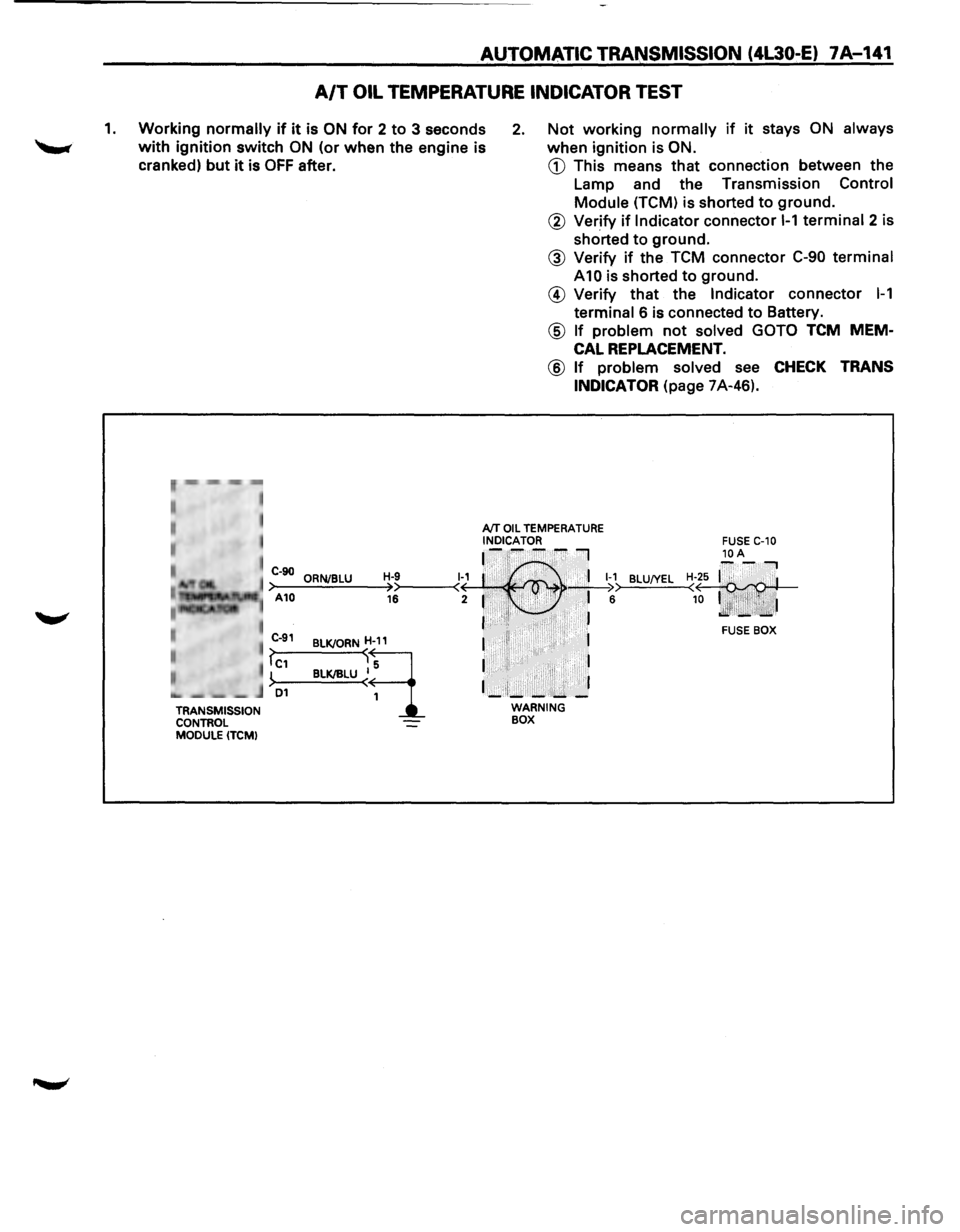
A/T OIL TEMPERATURE INDICATOR TEST
1. Working normally if it is ON for 2 to 3 seconds
with ignition switch ON (or when the engine is
cranked)
but it is OFF after.
2. Not working normally if it stays ON always
when ignition is ON.
CD This means that connection between the
Lamp and the Transmission
Control
Module (TCM) is shorted to ground.
r~,··mm -,-,~
• , I
I
TRANSMISSION
CONTROL
MODULE (TCM)
@ Verify if Indicator connector 1-1 terminal 2 is
shorted
to ground.
@ Verify if the TCM connector C-90 terminal
A10 is shorted to ground.
@ Verify that the Indicator connector 1-1
terminal 6 is connected to Battery.
@ If problem not solved GOTO TCM MEM
CAL REPLACEMENT.
@ If problem solved see CHECK TRANS
INDICATOR
(page 7A-46).
AfT OIL TEMPERATURE INDICATOR ~-~--~I
C-90 ORNJBLU H-9 1~1 :·' ,.· . 'I 1-1 >-A-10--=.:..;.;_;:,=-~>>----<( · , . ' >• • _;__I ;:. 16 2 1 . • .i· ,..:., • 6
I ·•'I• ·. . , . . J
BLU!YEL
BLKJORND
BLK/IILU ~~
I II 1
I I
1_:1;_-:....... _]
WARNING BOX
FUSE BOX
Page 1019 of 1928
AUTOMATIC TRANSMISSION (4L30-E) 7A-147
TCM MEM-CAL REPLACEMENT
(TCM: Transmission Control Module)
1. MEM-CAL (Memory and Calibration Unit)
Information for specific transmission and vehicle is
programmed using an integrated circuit called a
MEM-CAL.
This allows one model of controller to be used for
many different vehicles.
The MEM-CAL is located inside the TCM and has
information on the transmission, shift map, etc.
several others.
2. MEM-CAL Replacement
If the diagnostic procedures require MEM-CAL
replacement,
the MEM-CAL should be replaced
using the following procedures.
NOTICE:
The ignition must be "OFF", when disconnecting or
reconnecting the TCM connector, to prevent
internal damage to the TCM.
NOTICE:
To prevent possible Electrostatic Discharge damage
to the TCM, do not touch the connector pins or
soldered components on the circuit board.
MEM-CAL Replacement Procedure:
1. Remove TCM from driver compartment (Fig.
7A-10a):
( 1) Disconnect negative (-) battery cable.
(2) Remove connectors from TCM.
(3) Remove TCM from driver compartment.
(4) Remove MEM-CAL access cover.
NOTE:
Do not remove any of the other screws.
Fig.
7A-10a
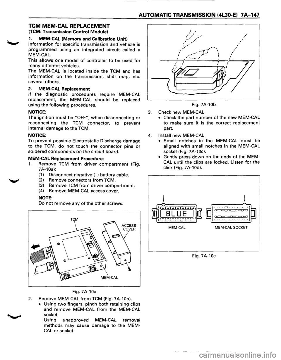
2. Remove MEM-CAL from TCM (Fig. 7A-10b).
•
Using two fingers, pinch both retaining clips
and remove MEM-CAL from the MEM-CAL
socket.
Using unapproved
methods may cause
CAL or socket.
MEM-CAL removal
damage to the MEM- Fig.
7A-10b
3. Check new MEM-CAL
• Check
the part number of the new MEM-CAL
to make sure it is the correct replacement
part.
4. Install new MEM-CAL
• Small notches in the MEM-CAL must be
aligned with small notches in the MEM-CAL
socket (Fig.
7A-10c).
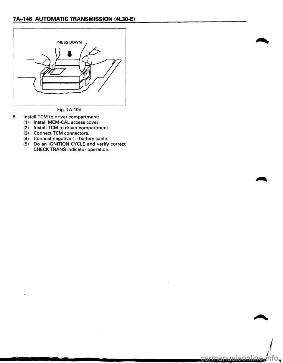
• Gently
press down on the ends of the MEM
CAL
until the clips are locked. Listen for the
click (Fig. 7A-10d).
! !
($I~rn~ ~~~) . . . . . . . . . . . . . . . ............ .
MEM-CAL MEM-CAL SOCKET
Fig. 7A-10c
Page 1020 of 1928
7A-148 AUTOMATIC TRANSMISSION (4L30-E)
Fig. 7A-10d
5. Install TCM to driver compartment:
(1) Install MEM-CAL access cover.
(2) Install TCM to driver compartment.
(3) Connect TCM connectors.
(4) Connect negative(-) battery cable.
(5) Do an IGNITION CYCLE and verify correct
CHECK TRANS indicator operation.
l
--------~.-------~------------~~--~'1
Page 1028 of 1928
7A-156 AUTOMATIC TRANSMISSION (4L30-E)
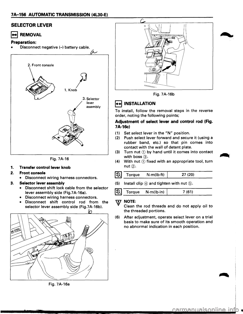
SELECTOR LEVER
B REMOVAL
Preparation:
• Disconnect negative (-) battery cable.
(}-
2. Front console
)3
1. Knob
Fig. 7A-16
1. Transfer control lever knob
2. Front console
3. Selector
lever
assembly
• Disconnect wiring harness connectors.
3. Selector lever assembly
• Disconnect shift lock cable from the selector
lever assembly
side (Fig.7A-16a).
• Disconnect wiring harness connectors.
• Disconnect shift control rod from the
selector lever assembly side (Fig.7A-16b).
Fig. 7A-16a Fig.
7A-16b
I••IINSTALLATION
To install, follow the removal steps in the reverse
order,
notin!~ the following points;
Adjustment of select lever and control rod (Fig.
7A-16c)
(1) Set sele1ct lever in the "N" position.
(2) Push select lever forward and secure it (using a
rubber band, etc.) so that pin comes into
contact with the wall of detent plate.
(3) Turn nut CD by hand until it comes into contact
with boss@.
(4) With nut CD fixed with an appropriate tool, turn
nut®.
~~~ Torque N·mOb·ft) I 27 (20)
(5) Install clip @ and tighten with nut @.
~~~ Torque N·m(lb·in) I 7 (61)
w NOTE:
Clean the rod threads and do not apply oil to
the threaded portions.
(6) After adjustment, operate select lever on a trial
basis to make sure of its smooth operation and
no
abnormal indication in each position.
.......
..._.
II
Page 1029 of 1928
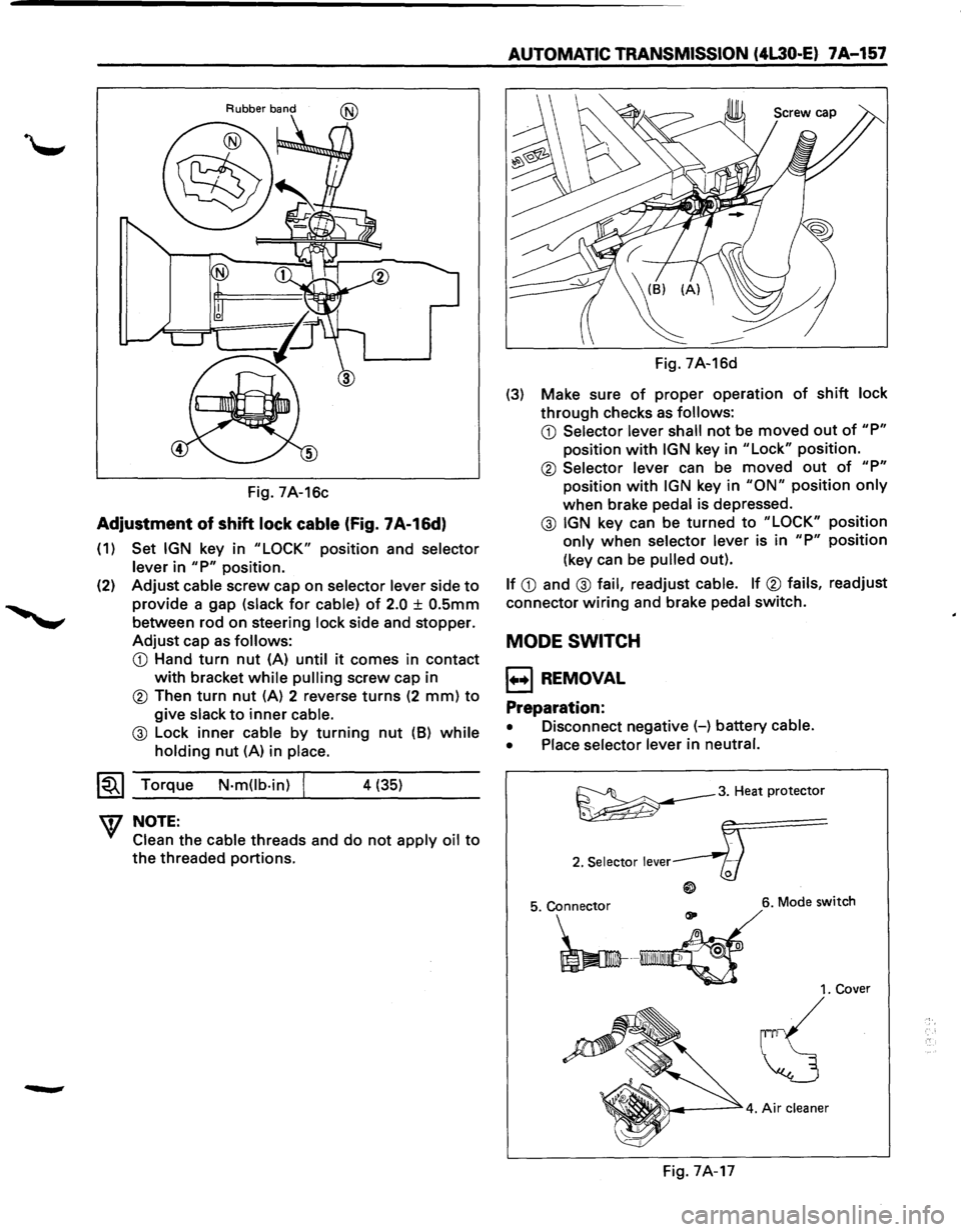
Rubber band
Fig. 7A-16c
Adjustment of shift lock cable (Fig. 7A-16d)
(1) Set IGN key in "LOCK" position and selector
lever
in "P" position.
(2)
Adjust cable screw cap on selector lever side to
provide a gap (slack for cable) of 2.0 ± O.Smm
between rod on steering lock side and stopper.
Adjust cap as follows:
CD Hand turn nut (A) until it comes in contact
with bracket while pulling screw cap in
® Then turn nut (A) 2 reverse turns (2 mm) to
give slack to inner cable.
@ Lock inner cable by turning nut (8) while
holding nut (A) in place.
~~~ Torque N-m(lb-in) j 4 (35)
W NOTE:
Clean the cable threads and do not apply oil to
the threaded portions.
AUTOMATIC TRANSMISSION (4L30·E) 7A-157
Fig. 7A-16d
(3) Make sure of proper operation of shift lock
through checks as follows:
CD Selector lever shall not be moved out of "P"
position with IGN key in "Lock" position.
® Selector lever can be moved out of "P"
position with IGN key in "ON" position only
when brake pedal is depressed.
@ IGN key can be turned to "LOCK" position
only when selector lever is in "P" position
(key can be
pulled out).
If CD and @ fail, readjust cable. If ® fails, readjust
connector
wiring and brake pedal switch.
MODE SWITCH
1++1 REMOVAL
Preparation:
• Disconnect negative (-) battery cable.
• Place selector lever
in neutral.
~3. Heat protector
2. Selector lever
6. Mode switch
1. Cover
~
Fig. 7A-17
Page 1033 of 1928
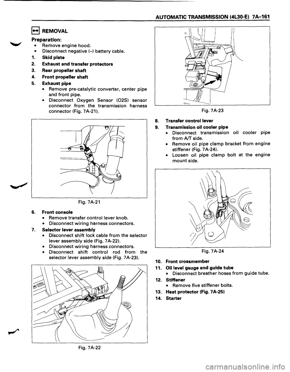
1••1 REMOVAL
Preparation:
• Remove engine hood.
• Disconnect negative (-) battery cable.
1. Skid plate
2. Exhaust and transfer protectors
3. Rear propeller shaft
4. Front propeller shaft
5. Exhaust pipe
• Remove pre-catalytic converter, center pipe
and
front pipe.
• Disconnect Oxygen Sensor (025) sensor
connector
from the transmission harness
connector (Fig.
7A-21).
Fig. 7A-21
6. Front console
• Remove transfer control lever knob.
• Disconnect wiring harness connectors.
7. Selector lever assembly
• Disconnect shift lock cable from the selector
lever assembly
side (Fig. 7 A-22).
• Disconnect wiring harness connectors.
• Disconnect shift control rod from the
selector lever assembly side (Fig. 7 A-23).
Fig. 7A-22
AUTOMATIC TRANSMISSION (4L30·E) 7A-161
Fig. 7A-23
8. Transfer control lever
9. Transmission oil cooler
pipe
• Disconnect transmission oil cooler pipe
from AfT side.
• Remove oil pipe clamp bracket from engine
stiffener (Fig.
7 A-24).
• Loosen oil pipe clamp bolt at the engine
mount side.
Fig.
7A-24
10. Front crossmember
11.
Oil level gauge and guide tube
• Disconnect breather hoses from guide tube.
12.
Stiffener
• Remove five stiffener bolts.
13. Heat protector (Fig. 7A-25}
14.
Starter
Page 1037 of 1928
2. Exhaust and transfer protectors
~~~ Torque N-m(lb.ft) 37 (27)
1. Skid plate
• Connect negative (-) battery cable.
• Install
engine hood.
• Adjust shift lock cable.
Refer to "Selector lever" in this section.
SOLENOID VALVE
(MAIN CASE VALVE BODY)
l••l REMOVAL
Preparation:
• Disconnect negative {-) battery cable.
•
Remove exhaust protector and exhaust pipe.
1. Main case oil pan
• Remove sixteen 10 mm screws, main case
oil pan, magnet, and gasket.
• Drain fluid.
Refer to "CHANGING TRANSMISSION
FLUID".
2. Oil filter
• Remove three 13 mm screws, oil filter.
3. Wiring harness
• Disconnect wiring harness from band control
solenoid,
shift solenoids and main case 4 pin
connector.
Pull only on connectors, not on
wiring harness.
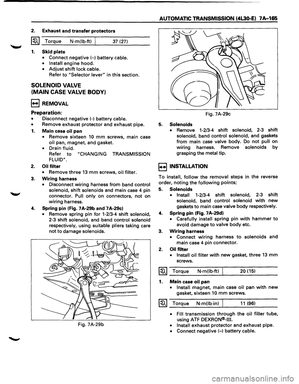
4. Spring pin (Fig. 7 A-29b and 7 A-29c)
• Remove spring pin for 1-2/3-4 shift solenoid,
2-3 shift solenoid, and band control solenoid
respectively,
using suitable pliers taking care
not to damage solenoids.
Fig. 7A-29b
AUTOMATIC TRANSMISSION (4L30 .. E) 7A-165
Fig. 7A-29c
5. Solenoids
• Remove 1-2/3-4 shift solenoid, 2-3 shift
solenoid, band control solenoid, and gaskets
from main case valve body. Do not pull on
wiring harness. Remove
· solenoids by
grasping the
metal tip.
I••! INSTALLATION
To install, follow the removal steps in the reverse
order,
noting the following points;
5. Solenoids
• Install 1-2/3-4 shift solenoid, 2-3 shift
solenoid, band control solenoid with new
gaskets to main case valve body respectively.
4. Spring pin (Fig. 7 A·29d)
• Carefully install spring pin with hammer to
avoid damage to valve body etc.
3. Wiring harness
• Connect wiring harness to solenoids and
main case 4 pin connector.
2. Oil filter
• Install oil filter with new gasket, three 13 mm
screws.
~~~ Torque N·m(lb.ft) 20 (15)
1. Main case oil pan
•
Install magnet, main case oil pan with new
gasket, sixteen 10 mm screws.
1~1 Torque N·m(lb·in) J 11 (96)
• Fill transmission through the oil filler tube,
using ATF DEXRQN®-m.
• Install exhaust protector and exhaust pipe.
• Connect negative (-) battery cable.
Page 1038 of 1928
7A-166 AUTOMATIC TRANSMISSION (4l30-E)
Fig. 7A-29d
SOLENOID VALVE
(ADAPTER CASE VALVE BODY)
l++l REMOVAL
Preparation:
• Disconnect negative(-) battery cable.
• Remove exhaust protector and exhaust pipe.
• Drain fluid.
• Refer to "CHANGING TRANSMISSION FLUID".
1. Adapter case oil pan
• Remove twelve 10 mm screws, adapter case
oil pan, and gasket.
NOTE:
Oil pan still contains transmission fluid. Place a
large
drain container under the oil pan.
Drain
the fluid carefully.
2. Wiring harness
• Disconnect wiring harness from force motor
solenoid, converter clutch solenoid and 5
pin
connector of adapter case. Pull only on
connectors,
not on wiring harness.
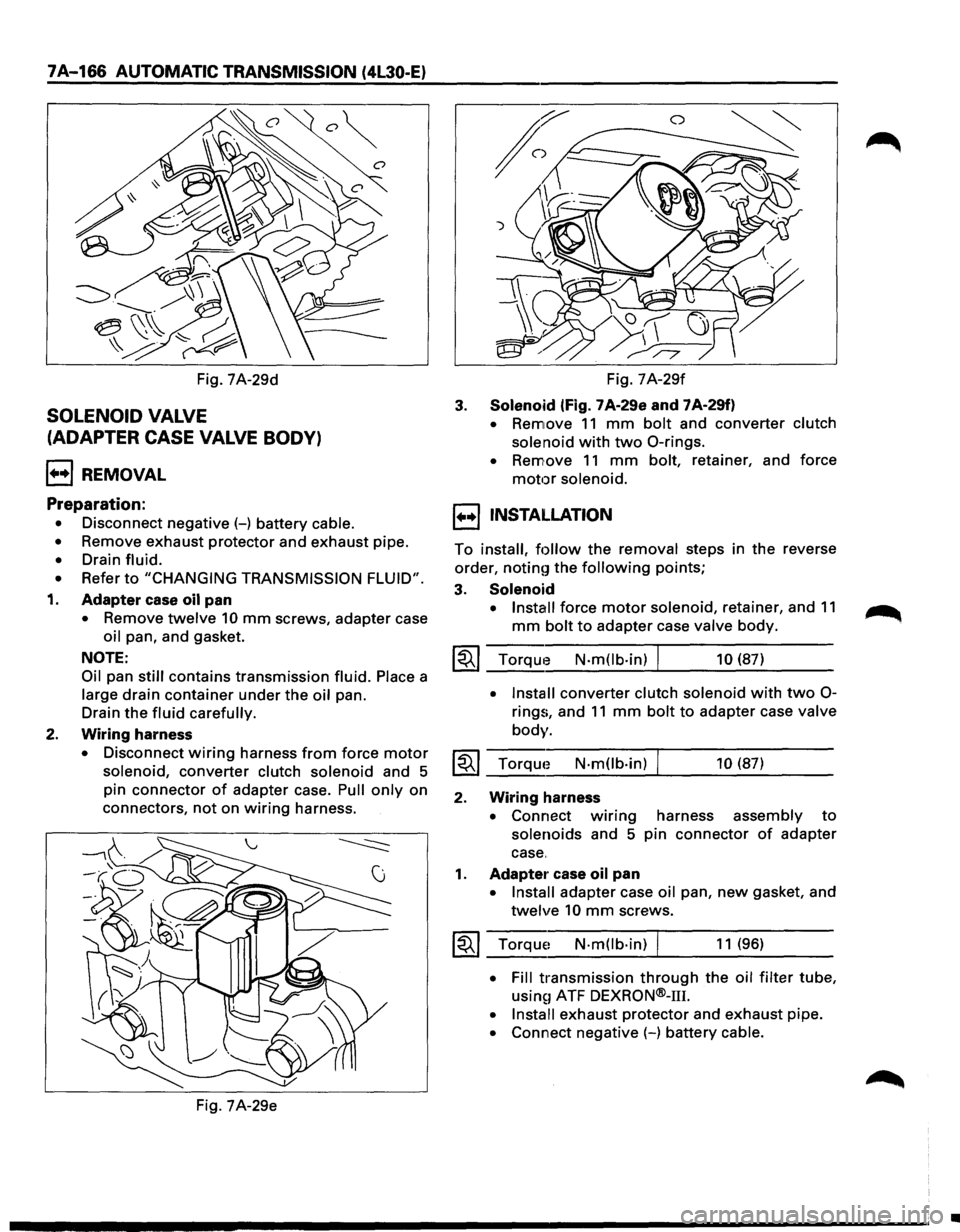
Fig. 7A-29e Fig.
7A-29f
3. Solenoid (fig. 7 A-29e and 7 A-29f)
• Remove 11 mm bolt and converter clutch
solenoid
with two 0-rings.
• Remove 11 mm bolt, retainer, and force
motor solenoid.
1••1 INSTALLATION
To install, follow the removal steps in the reverse
order,
noting the following points;
3. Solenoid
• Install force motor solenoid, retainer, and 11
mm bolt to adapter case valve body.
~~~ Torque N-m(lb-in) I 10 (87)
• Install converter clutch solenoid with two 0-
rings, and 11 mm bolt to adapter case valve
body.
~~~ Torque N-mOb·in) 10 (87)
2. Wiring harness
• Connect w1nng harness assembly to
solenoids and 5 pin connector of adapter
case.
1. Adapter case oil pan
• Install adapter case oil pan, new gasket, and
twelve 10 mm screws.
~~~ Torque~ N·mOb·in) I 11 (96)
• Fill transmission through the oil filter tube,
usin~1 ATF DEXRON®-111.
• Install exhaust protector and exhaust pipe.
• Connect negative (-) battery cable.
•
Page 1039 of 1928
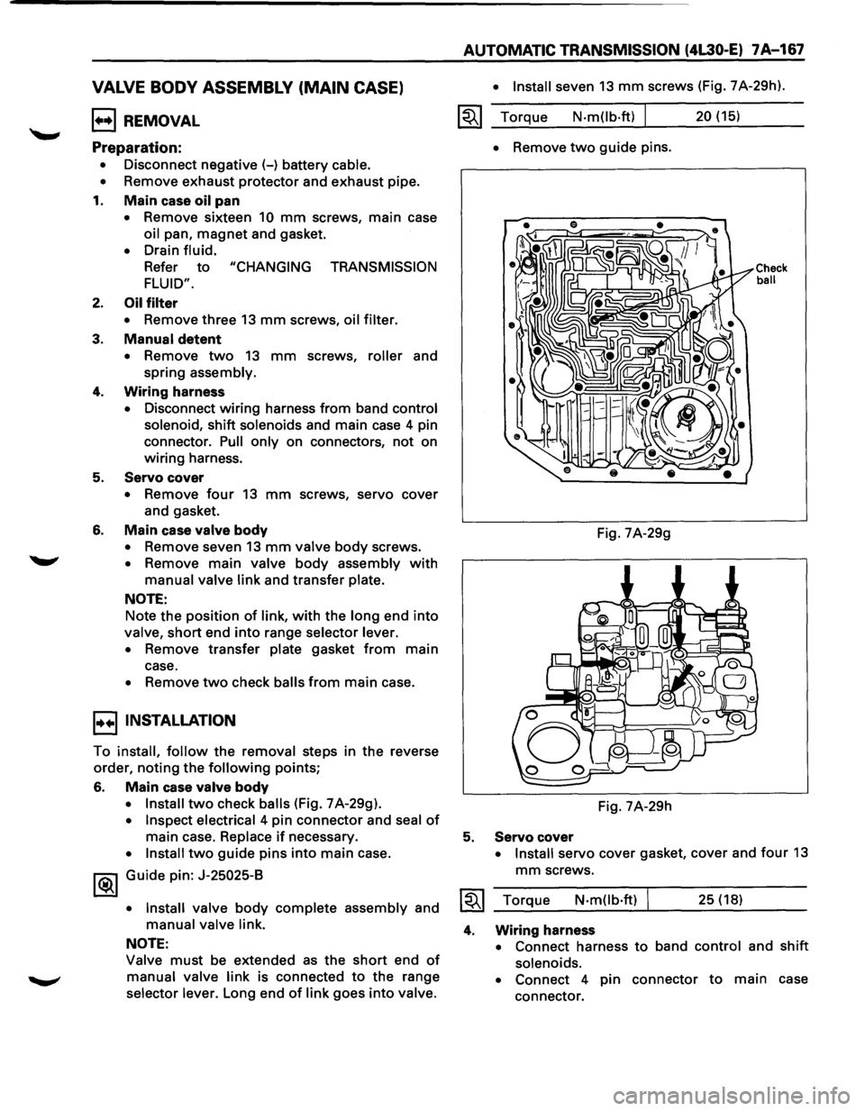
VALVE BODY ASSEMBLY (MAIN CASE)
1••1 REMOVAL
Preparation:
• Disconnect negative (-) battery cable.
• Remove exhaust protector and exhaust pipe.
1. Main case oil pan
• Remove sixteen 10 mm screws, main case
oil pan,
magnet and gasket.
• Drain fluid.
Refer
to "CHANGING TRANSMISSION
FLUID".
2. Oil filter
•
Remove three 13 mm screws, oil filter.
3. Manual detent
• Remove two 13 mm screws, roller and
spring assembly.
4. Wiring harness
• Disconnect wiring harness from band control
solenoid, shift solenoids and main
case 4 pin
connector.
Pull only on connectors, not on
wiring harness.
5.
Servo cover
• Remove four 13 mm screws, servo cover
and gasket.
6. Main case valve body
• Remove seven 13 mm valve body screws.
• Remove main valve body assembly with
manual valve link and transfer plate.
NOTE:
Note the position of link, with the long end into
valve, short end into range selector lever.
• Remove transfer plate gasket from main
case.
• Remove two check balls from main case.
I••IINSTALLATION
To install, follow the removal steps in the reverse
order,
noting the following points;
6. Main
case valve body
• Install two check balls (Fig. 7 A-29g).
• Inspect electrical 4 pin connector and seal of
main case. Replace if necessary.
• Install two guide pins into main case.
1®.1 Guide pin: J-25025-B
• Install
valve body complete assembly and
manual valve link.
NOTE:
Valve must be extended as the short end of
manual valve link is connected to the range
selector lever. Long end
of link goes into valve.
AUTOMATIC TRANSMISSION (4L30-E) 7A-167
• Install seven 13 mm screws (Fig. 7A-29h).
~~~ Torque N·m(lb·ft) I 20 (15)
5.
4.
• Remove two guide pins.
Fig. 7A-29g
Fig. 7A-29h
Servo cover
Check ball
• Install servo cover gasket, cover and four 13
mm screws.
Torque
N·mOb·ft) I 25 (18)
Wiring harness
• Connect harness to band control and shift
solenoids.
• Connect 4 pin connector to main case
connector.
Page 1040 of 1928
7A-168 AUTOMATIC TRANSMISSION (4L30-E)
3. Manual detent
• Install roller and spring assembly.
• Install
two 13 mm screws.
~~~ Torque N·m(lb.ft) I 20 (15)
2. Oil filter
• Install oil filter and three 13 mm screws.
~~~ Torque N-m(lb.ft) I 20 (15)
1. Main case oil pan
• Install oil pan gasket, magnet, oil pan and
sixteen
10 mm screws.
~~~ Torque N·m(lb-in) I 11 (96)
• Fill transmission through the oil filler tube,
using ATF
DEXRON®-111.
• Install exhaust pipe and exhaust protector.
• Connect negative (-) battery cable.
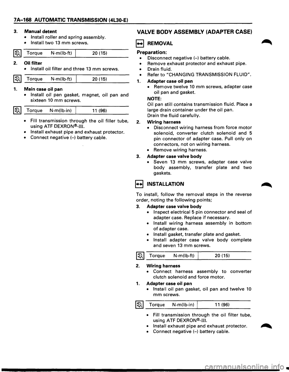
VALVE BODY ASSEMBLY (ADAPTER CASE)
1++1 REMOVAL
Preparation:
• Disconnect negative (-) battery cable.
•
Remove exhaust protector and exhaust pipe.
• Drain fluid.
•
Refer to "CHANGING TRANSMISSION FLUID".
1. Adapter case oil pan
• Remove twelve 10 mm screws, adapter case
oil pan and gasket.
NOTE:
Oil pan still contains transmission fluid. Place a
large drain container under the oil pan.
Drain the
fluid carefully.
2. Wiring harness
• Disc;:mnect wiring harness from force motor
solenoid, converter clutch solenoid and 5
pin
connector of adapter case. Pull only on
connectors,
not on wiring harness.
• Remove wiring harness.
3. Adapter case valve body
• Seve~n 13 mm screws, adapter case valve
body assembly, transfer plate and two
gaskets.
1++1 INSTALLATION
To install, follow the removal steps in the reverse
order,
notin~r the following points;
3. Adapter case valve body
• Inspect electrical 5 pin connector and seal of
adapter case. Replace if necessary.
• Install wiring harness assembly in bottom
of adapter case.
• Install gasket, transfer plate and gasket.
• Install adapter case valve body complete
and seven 13 mm screws.
~~~ Torque1 N·mOb·ft) 20 (15)
2. Wiring harness
• Connect harness assembly to converter
clutch solenoid and force motor.
1. Adapter case oil pan
• Instal!! oil pan gasket, oil pan and twelve 10
mm screws.
~~~ Torque N-m(lb-in) I 11 (96)
• Fill transmission through the oil filter tube,
using1 ATF DEXRON®-m.
• Install exhaust pipe and exhaust protector. ~
• Connect negative (-) battery cable.
•