battery ISUZU TROOPER 1995 Workshop Manual
[x] Cancel search | Manufacturer: ISUZU, Model Year: 1995, Model line: TROOPER, Model: ISUZU TROOPER 1995Pages: 1928
Page 805 of 1928
DRIVEABILITY AND EMISSIONS 6E2-1 09
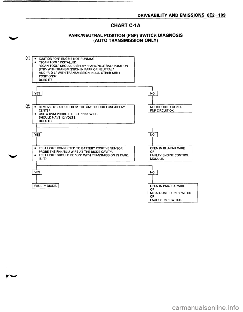
CHART C-1A
PARK/NEUTRAL POSITION (PNP) SWITCH DIAGNOSIS
(AUTO TRANSMISSION ONLY)
CD • IGNITION "ON" ENGINE NOT RUNNING.
• "SCAN TOOL" INSTALLED.
"SCAN TOOL" SHOULD DISPLAY "PARK/NEUTRAL" POSITION
(PNP} WITH TRANSMISSION
IN PARK OR NEUTRAL?
AND "R·D-L" WITH TRANSMISSION IN ALL OTHER SHIFT
POSITIONS?
DOES
IT?
@ • REMOVE THE DIODE FROM THE UNDERHOOD FUSE/RELAY CENTER. • USE A DVM PROBE THE BLU/PINK WIRE.
SHOULD HAVE 12 VOLTS.
DOES IT?
• TEST LIGHT CONNECTED TO BATTERY POSITIVE SENSOR,
PROBE THE PNK/BLU WIRE AT THE DIODE CAVITY.
• TEST LIGHT SHOULD BE "ON" WITH TRANSMISSION IN PARK.
IS IT?
OPEN IN BLU/PNK WIRE OR FAULTY ENGINE CONTROL
MODULE.
OPEN
IN PNK/BLU WIRE OR MISADJUSTED PNP SWITCH OR FAULTY PNP SWITCH.
Page 808 of 1928
6E2-112 DRIVEABILITY AND EMISSIONS
CHART C-1E
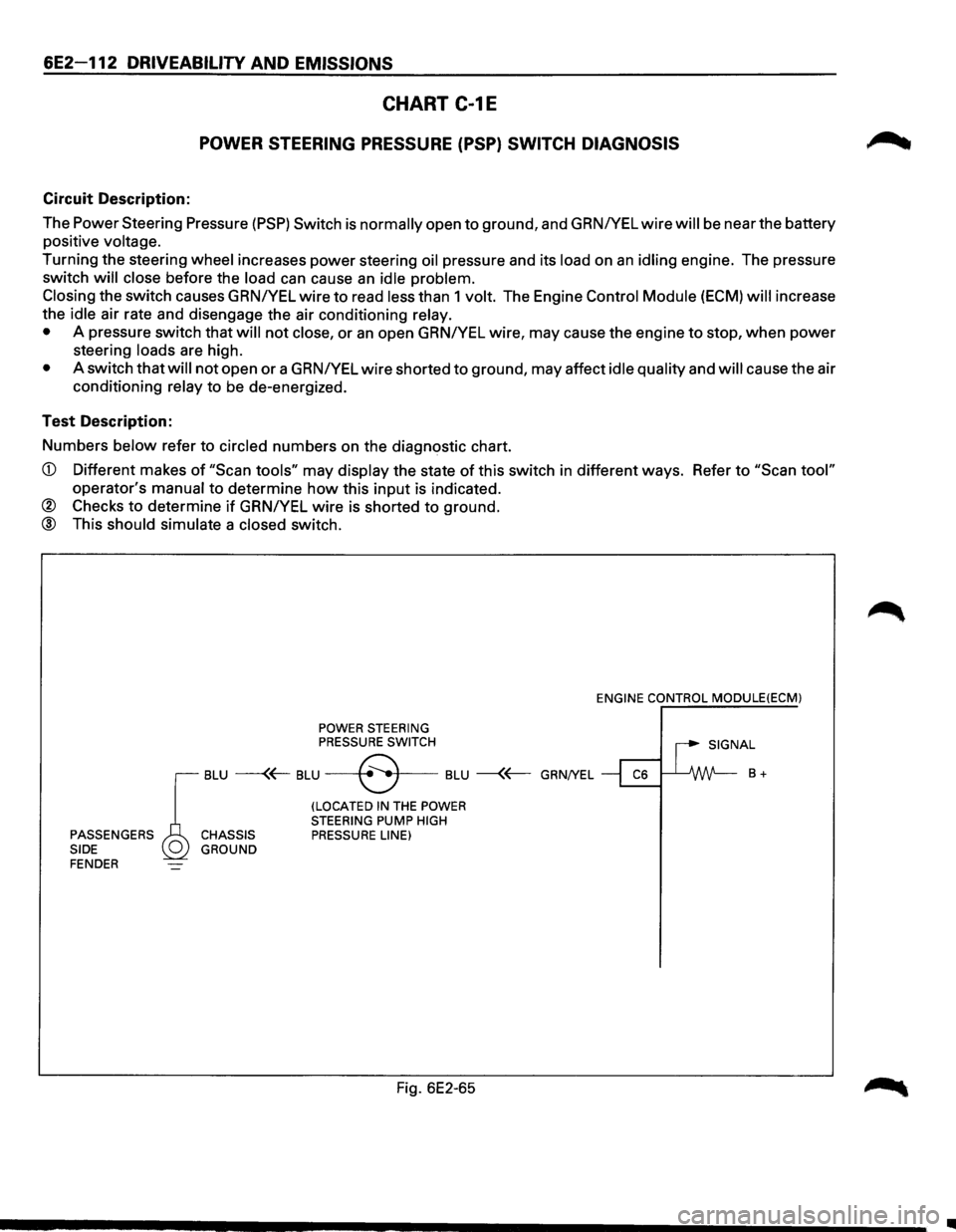
POWER STEERING PRESSURE (PSP) SWITCH DIAGNOSIS
Circuit Description:
The Power Steering Pressure
(PSP) Switch is normally open to ground, and GRNIYEL wire will be near the battery
positive
voltage.
Turning the steering wheel increases power steering oil pressure and its load on an idling engine. The pressure
switch
will close before the load can cause an idle problem.
Closing
the switch causes GRN/YEL wire to read less than 1 volt. The Engine Control Module (ECM) will increase
the
idle air rate and disengage the air conditioning relay.
•
A pressure switch that will not close, or an open GRNIYEL wire, may cause the engine to stop, when power
steering loads are high.
• A switch that will not open or a GRNIYEL wire shorted to ground, may affect idle quality and will cause the air
conditioning
relay to be de-energized.
Test Description:
Numbers
below refer to circled numbers on the diagnostic chart.
CD Different makes of "Scan tools" may display the state of this switch in different ways. Refer to "Scan tool"
operator's manual to determine how this input is indicated.
® Checks to determine if GRNIYEL wire is shorted to ground.
@ This should simulate a closed switch.
POWER STEERING PRESSURE SWITCH ENGINE
CONTROL
MODULE(ECM)
I SIGNAL
r
BLU ---(~ BLU --+8 .. •f---BLU --{~ GRN/YEL ~ ~ B +
(LOCATED IN THE POWER
STEERING PUMP HIGH PASSENGERS CHASSIS PRESSURE LINE)
SIDE GROUND
FENDER
Fig. 6E2-65
•
Page 810 of 1928
6E2-114 DRIVEABILITY AND EMISSIONS
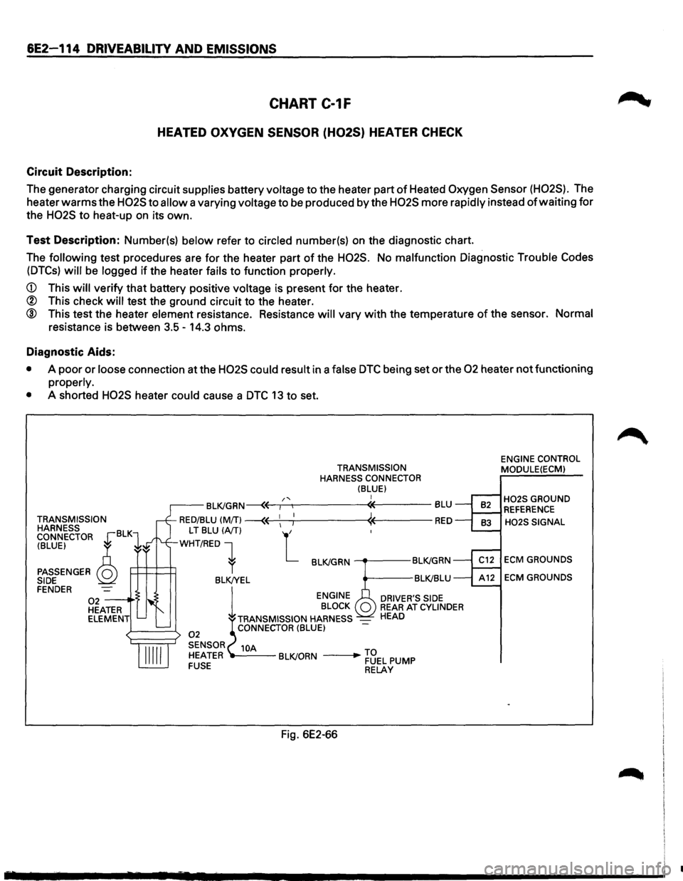
CHART C-1F
HEATED OXYGEN SENSOR (H02S} HEATER CHECK
Circuit Description:
The generator charging circuit supplies battery voltage to the heater part of Heated Oxygen Sensor (H02S). The
heater
warms the H02S to allow a varying voltage to be produced by the H02S more rapidly instead of waiting for
the H02S to heat-up on its own.
Test Description: Number(s) below refer to circled number(s) on the diagnostic chart.
The
following test procedures are for the heater part of the H02S. No malfunction Diagnostic Trouble Codes
(DTCs) will be logged if the heater fails to function properly.
CD This will verify that battery positive voltage is present for the heater.
® This check will test the ground circuit to the heater.
® This test the heater element resistance. Resistance will vary with the temperature of the sensor. Normal
resistance is between 3.5-14.3 ohms.
Diagnostic Aids:
• A poor or loose connection at the H02S could result in a false DTC being set or the 02 heater not functioning
properly.
•
A shorted H02S heater could cause a DTC 13 to set.
TRANSMISSION
HARNESS
CONNECTOR
~BLKl
(BLUE) ~ ~
PASSENGER Q SIDE FENDER 02--·'> HEATER
ELEMENT
TRANSMISSION
HARNESS CONNECTOR
(BLUE) I
Fig. 6E2-66
ENGINE CONTROL
MODULE(ECM)
H02S GROUND REFERENCE
H02S SIGNAL
ECM GROUNDS
ECM GROUNDS
•
Page 811 of 1928
DRIVEABILITY AND EMISSIONS 6E2-115
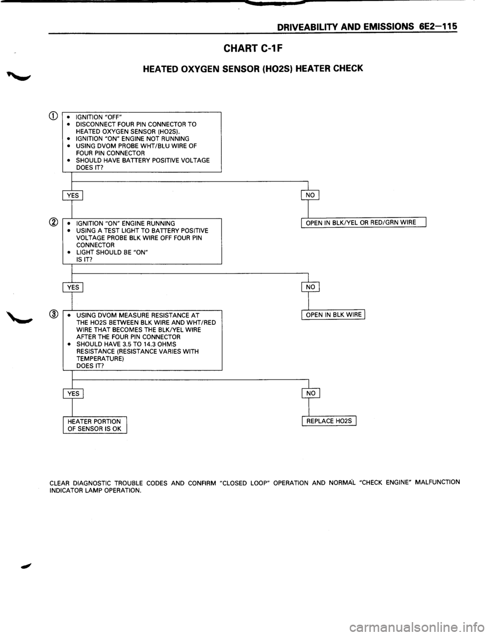
CHART C-1F
HEATED OXYGEN SENSOR (H02S) HEATER CHECK
CD • IGNITION "OFF"
• DISCONNECT FOUR PIN CONNECTOR TO HEATED OXYGEN SENSOR (H02S).
• IGNITION "ON" ENGINE NOT RUNNING • USING DVOM PROBE WHT /BLU WIRE OF FOUR PIN CONNECTOR
• SHOULD HAVE BATTERY POSITIVE VOLTAGE
DOES IT?
@ • IGNITION "ON" ENGINE RUNNING
• USING A TEST LIGHT TO BATTERY POSITIVE
VOLTAGE PROBE BLK WIRE OFF FOUR PIN CONNECTOR
• LIGHT SHOULD BE "ON" IS IT?
@ • USING DVOM MEASURE RESISTANCE AT THE H02S BETWEEN BLK WIRE AND WHT/RED WIRE THAT BECOMES THE BLK/YEL WIRE AFTER THE FOUR PIN CONNECTOR
• SHOULD HAVE 3.5 TO 14.3 OHMS
RESISTANCE (RESISTANCE VARIES WITH
TEMPERATURE) DOES IT?
OPEN IN BLK/YEL OR RED/GRN WIRE
CLEAR DIAGNOSTIC TROUBLE CODES AND CONFIRM "CLOSED LOOP" OPERATION AND NORMAL "CHECK ENGINE" MALFUNCTION
INDICATOR LAMP OPERATION.
Page 812 of 1928
6E2-116 DRIVEABILITY AND EMISSIONS
SECTION C-2
FUEL METERING SYSTEM
CONTENTS
General Description ...................... 6E2-116
Purpose ............................ 6E2-116
Modes of Operation .................... 6E2-117
Starting Mode ...................... 6E2-117
Clear Flood Mode .................... 6E2-117
RunMode ......................... 6E2-117
"Open Loop" ....................... 6E2-117
"Closed Loop" ...................... 6E2-117
Acceleration Mode ................... 6E2-117
Deceleration Mode ................... 6E2-117
Battery Positive Voltage Correction Mode ... 6E2-117
Fuel Cutoff Mode .................... 6E2-117
Fuel Metering System Components ........... 6E2-118
Fuel Supply System .................... 6E2-118
Fuel Pump Electrical Circuit ............... 6E2-118
Fuel Rail Assembly ..................... 6E2-118
Fuel Injectors ......................... 6E2-119
Fuel Injector Driver Operation ............. 6E2-119
Fuel Pressure Control Valve Assembly ....... 6E2-119
Throttle Body (TB) Assembly .............. 6E2-120
Idle Air Control (lAC) Valve .............. 6E2-120
Throttle Position (TP) Sensor ............ 6E2-121
Induction Air Control Plate System ......... 6E2-121
Diagnosis . . . . . . . . . . . . . . . . . . . . . . . . . . . . . 6E2-121
Fuel Metering System . .
. . . . . . . . . . . . . . . . 6E2-121
Fuel System Pressure Test ............... 6E2-121
Idle Air Control (lAC) Valve . .
. . . . . . . . . . . . . 6E2-121
Induction Air Control Plate System ......... 6E2-122
On-Vehicle Service ...................... 6E2-122
Fuel Pump Relay . . . . . . . . . . . . . . . . . . . . . . 6E2-122
Multipart Fuel Injection Components . . . . . . . . 6E2-122 Fuel Pressure Relief Procedure . . . . . . . . . . 6E2-122
Fuel Rail Assembly . . . . . . . . . . . . . . . . . . . . 6E2-122
Unit Repair ............................ 6E2-123
Fuel Injector/Rail ...................... 6E2-123
Throttle Body Assembly . . . . . . . . . . . . . . . . . 6E2-124
Throttle Body (TB) . . . . . . . . . . . . . . . . . . . 6E2-125
Throttle Position (TP) Sensor . . . . . . . . . . . . . 6E2-126
Idle Air Control (lAC) Valve ............... 6E2-126
Minimum Throttle Body (TB) Position Check ... 6E2-127
Chart C-2A Injector Balance ................ 6E2-128
Chart C-2C Idle Air Control (lAC) System Check .. 6E2-130
Chart C-2D Induction Air Control Plate
System Check . .
. . . . . . . . . . . . . . . . . . . . . . 6E2-132
GENERAL DESCRIPTION
PURPOSE
The function of the fuel metering system is to deliver
the correct amount of fuel to the engine under all
operating conditions. Fuel is delivered to the engine by
individual fuel injectors mounted in the intake manifold
near each cylinder.
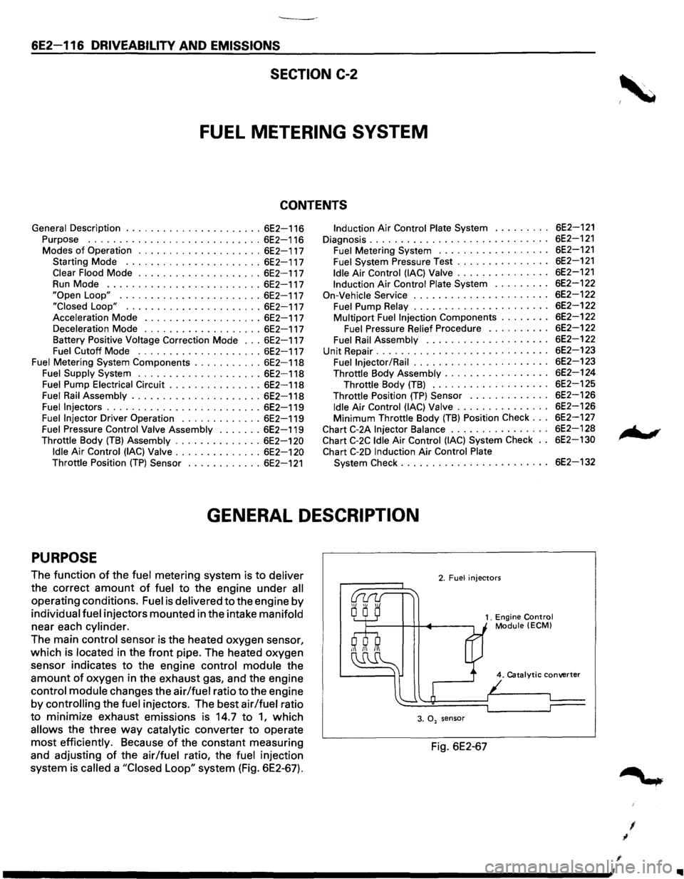
The main control sensor is the heated oxygen sensor,
which is located in the front pipe. The heated oxygen
sensor indicates
to the engine control module the
amount of oxygen in the exhaust gas, and the engine
control module changes the air/fuel ratio to the engine
by
controlling the fuel injectors. The best air/fuel ratio
to minimize exhaust emissions is 14.7 to
1, which
allows the three way catalytic converter to operate
most efficiently. Because of the constant measuring
and adjusting
of the air/fuel ratio, the fuel injection
system
is called a "Closed Loop" system (Fig. 6E2-67).
2. Fuel injectors
1. Engine Control Module (ECMl
4. Catalytic converter
3. 0, sensor
Fig. 6E2-67
I
I
Page 813 of 1928
MODES OF OPERATION
The Engine Control Module (ECM) uses voltage inputs
from several sensors to determine how much fuel to
give the engine. The fuel is delivered under one of
several conditions, called "modes". All the modes are
controlled by the ECM and are described below.
Starting Mode
When the ignition is first turned "ON", the ECM turns
"ON" the fuel pump relay for two seconds, and the fuel
pump builds up pressure. The ECM also checks the
Engine
Coolant Temperature (ECT) sensor and the
Throttle Position Sensor, and the determines the
proper
air/fuel ratio for starting. This ranges from 1.5:1
-36·c (-33.F) to 14.7:1, at 94•c (201.F) ECT.
The ECM controls the amount of fuel delivered in the
starting mode by changing
how long the injector is
turned
"ON" and "OFF". The is done by "Pulsing" the
injectors
for very short times.
Clear Flood Mode
If the engine floods, it may be cleared by pushing the
accelerator pedal down all the way. The ECM then will
fixed air/fuel ratio 16.5:1. The ECM holds this injector
rate
as long as the throttle stays wide open. If the
throttle position becomes less than approximately
70%, the ECM returns to the starting mode.
Run Mode
The run mode has two conditions called "Open Loop"
and "Closed Loop"
"Open Loop"
When the engine is first started, and it is above 500
Rovolution Per Minute (rpm), the system goes into
"Open Loop" operation. IN "Open Loop," the ECM
ignores the signal from the heated oxygen sensor
(H02S), and calculates the air/fuel ratio based on
inputs
from the ECT sensor and manifold absolute
pressure sensors.
The system stays in
"Open Loop" until the following
conditions are met:
1. The H02S has varying voltage output, showing
that
it is hot enough to operate properly. (This
depends on temperature.)
2. The ECT sensor is above a specified temperature.
3. A specific amount of time has elapsed after
starting the engine.
"Closed Loop"
The specific values for the above conditions vary with
different engines, and are stored in the ECM. When
these conditions are met, the system goes into
"Closed
Loop"
operation. In "Closed Loop", the ECM calculates
the air/fuel ratio (injector on-time) based on the signal
from the H02S. This allows the air/fuel ratio to stay
very close to 14.7:1.
DRIVEABILITV AND EMISSIONS 6E2-117
Acceleration Mode
The ECM responds to rapid changes in throttle position
and air
flow, and provides extra fuel.
Deceleration Mode
The ECM responds to changes in throttle position and
air
flow, and reduces the amount of fuel. When
deceleration is very fast, the ECM can cut off fuel
completely
for short periods.
Battery Positive Voltage Correction Mode
When battery positive voltage is low, the ECM can
compensate
for a weak spark delivered by the ignition
control module by:
• Increasing injector pulse width.
• Increasing the idle rpm.
• Increasing ignition dwell time.
Fuel Cutoff Mode
The fuel injectors are shut "OFF" if engine speed
"exceed" 6880 rpm (DOHC) or6800 rpm (SOHC). This is
to prevent damage to engine. When engine speed is
below 6880 rpm (DOHC) or 6800 rpm (SOHC), the fuel
injectors are again pulsed at a normal mode.
Page 815 of 1928
FUEL INJECTORS
The multipart fuel injection injector assembly is a
solenoid-operated device, controlled
by the Engine
Control Module (ECM), that meters pressurized fuel to
a single engine cylinder.
The
ECM energizes the low impedance (2.0 ohms) for
DOHC or High impedance (12.2 ohms) for SOHC
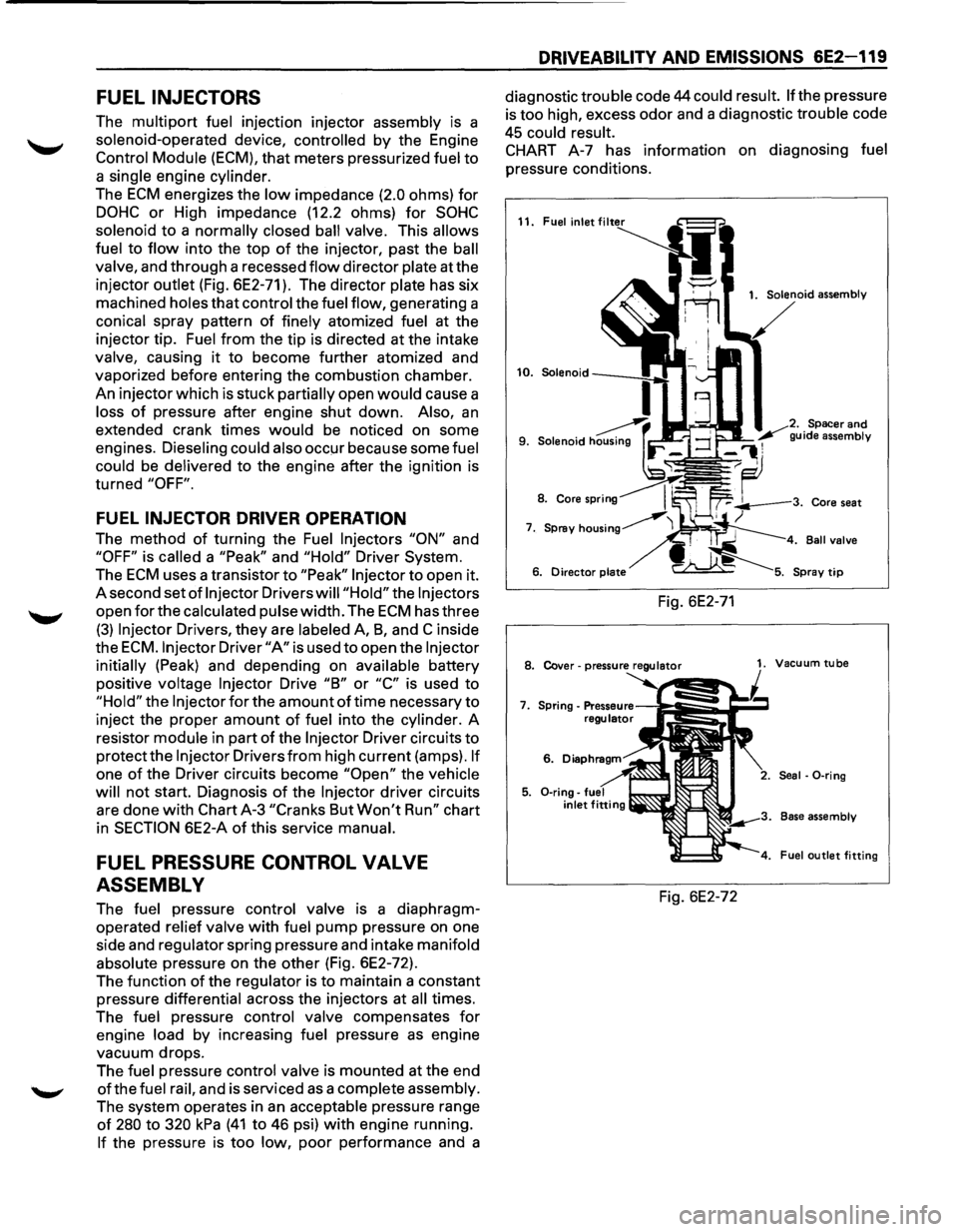
solenoid to a normally closed ball valve. This allows
fuel
to flow into the top of the injector, past the ball
valve, and through a recessed
flow director plate at the
injector outlet (Fig. 6E2-71). The director plate has six
machined holes
that control the fuel flow, generating a
conical spray pattern
of finely atomized fuel at the
injector tip. Fuel
from the tip is directed at the intake
valve, causing
it to become further atomized and
vaporized before entering the combustion chamber.
An injector which is stuck partially open
would cause a
loss
of pressure after engine shut down. Also, an
extended crank times would be noticed on some
engines. Dieseling could also
occ!Jr because some fuel
could be delivered
to the engine after the ignition is
turned
"OFF".
FUEL INJECTOR DRIVER OPERATION
The method of turning the Fuel Injectors "ON" and
"OFF" is called a "Peak" and "Hold" Driver System.
The
ECM uses a transistor to "Peak" Injector to open it.
A second set
of Injector Drivers will "Hold" the Injectors
open for the calculated pulse width. The ECM has three
(3) Injector Drivers, they are labeled A, 8, and C inside
the
ECM. Injector Driver "A" is used to open the Injector
initially (Peak) and depending on available battery
positive voltage
Injector Drive "8" or "C" is used to
"Hold" the Injector for the amount of time necessary to
inject the proper amount of fuel into the cylinder. A
resistor module in part
of the Injector Driver circuits to
protect the Injector Drivers from high current (amps). If
one of the Driver circuits become "Open" the vehicle
will
not start. Diagnosis of the Injector driver circuits
are done
with Chart A-3 "Cranks But Won't Run" chart
in
SECTION 6E2-A of this service manual.
FUEL PRESSURE CONTROL VALVE
ASSEMBLY
The fuel pressure control valve is a diaphragm
operated relief valve
with fuel pump pressure on one
side and regulator spring pressure and intake manifold
absolute pressure on the other (Fig. 6E2-72).
The function
of the regulator is to maintain a constant
pressure differential across the injectors at all times.
The fuel pressure control valve compensates
for
engine load by increasing fuel pressure as engine
vacuum drops.
The fuel pressure control valve is mounted at the end
ofthe fuel rail, and is serviced as a complete assembly.
The system operates in
an acceptable pressure range
of 280 to 320 kPa (41 to 46 psi) with engine running.
If the pressure is too low, poor performance and a
DRIVEABILITV AND EMISSIONS 6E2-119
diagnostic trouble code 44 could result. If the pressure
is too high, excess odor and a diagnostic trouble code
45 could result.
CHART A-7 has information on diagnosing fuel
pressure conditions.
11. Fuel inlet
Fig. 6E2-71
1. Solenoid assembly
Spacer
and
guide assembly
. Ball valve
8. Cover-pressure regulator 1. Vacuum tube
7.
6.
Seal · 0-ring
Base assembly
Fuel
outlet fitting
Fig. 6E2-72
Page 816 of 1928
6E2 120 DRIVEABILITY AND EMISSIONS
THROTTLE BODY (TB) ASSEMBLY
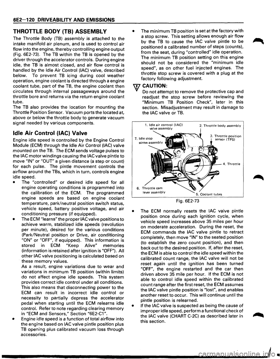
The Throttle Body (TB) assembly is attached to the
intake manifold air
plenum, and is used to control air
flow into the engine, thereby controlling engine output
(Fig. 6E2-73). The TB within the TB is opened by the
driver through the accelerator controls. During engine
idle, the
TB is almost closed, and air flow control is
handled by the Idle Air Control (lAC) valve, described
below. To prevent
TB icing during cool weather
operation, engine
coolant is directed through a engine
coolant tube, part
of the TB, the engine coolant then
circulates through internal passageways around the
throttle bore and returns via the return engine coolant
tube.
The
TB also provides the location for mounting the
Throttle Position
Sensor. Vacuum ports the located at,
above or
below the throttle body to generate vacuum
signal needed
by various components.
Idle Air Control (lAC) Valve
Engine idle speed is controlled by the Engine Control
Module (ECM) through the Idle Air Control (lAC) valve
mounted on the
TB. The ECM sends voltage pulses to
the lAC motor windings causing the lAC valve pintle to
move "IN" or "OUT" a given distance (a step or count)
for each pulse. The pintle movement controls the
airflow around the TBs, which in turn, controls engine
idle speed.
• The "controlled" or desired idle speed for all
engine operating conditions is programmed into
the
calibration of the ECM. The programmed
engine speeds are based on engine coolant
temperature, park/neutral position switch status,
vehicle speed, battery positive voltage, and air
conditioning pressure (if equipped).
• The ECM "learns" the proper lAC valve positions to
achieve warm, stabilized idle speeds (revolution
per minute), desired
for the various conditions
(Park/Neutral position
or Drive, air conditioning
"ON" or "OFF", if equipped). This information is
stored in
ECM "Keep Alive" memories
(information
is retained after ignition is "OFF"). All
other lAC valve positioning is calculated based on
these
memory values.
As a
result, engine variations due to wear and
variations in
minimum TB position (within limits)
do not affect engine idle speeds. This system
provides correct idle control under
all conditions.
This also means
that disconnecting power to the
ECM can result in incorrect idle control or
necessity to partially depress the accelerator
pedal
when starting until the ECM relearns idle
control. Refer to note regarding clearing
memory
in "ECM and Sensors," Section "6E2-C1 ".
•
Engine idle speed is a function of total airflow into
the engine based on
lAC valve pintle position plus
TB opening plus calibrated vacuum loss through
accessories.
• The minimum TB position is set at the factory with
a stop screw. This setting allows enough air flow
by the TB to cause the lAC valve pintle to be
positioned a calibrated
number of steps (counts),
from the seat, during "controlled" idle operation.
The
minimum TB position setting on this engine
should not be considered the
"minimum idle
speed", as on other fuel injected engines. The
throttle stop
screw is covered with a plug at the
factory
following adjustment.
U7 CAUTION:
VI Do not attempt to remove the protective cap and
readjust the stop screw before
reviewi~g t~e
"Minimum TB Position Check", later m th1s
section. Misadjustment may result in damage to
the lAC valve or TB.
Fig. 6E2-73
2. Throttle body assembly
3. Throttle position sensor (TPS)
• The ECM normally resets the lAC valve pintle
position once during each ignition cycle,
when
vehicle speed increases above 35 miles per hour
on moderate acceleration. During the reset, the
ECM commands the lAC valve pintle to retract
completely, then move
"IN" to the seated position
(to establish the zero
count position), and then
back
out to the desired position. If, after the reset,
the
ECM is able to control the idle speed within the
calibrated count range, the
lAC valve will not be
reset again until the ignition has been turned
"OFF", the engine restarted and the car then
driven above 35 mile per hour.
If the ECM is not
able to control idle speed within the calibrated
count range after the first reset, the
ECM assumes
the
lAC valve pintle position is "lost", and enables
another reset
to occur. This will continue until the
pintle position is relearned.
• If the lAC valve is suspected as being the cause of
improper idle speed, perform a functional check of
the lAC valve (CHART C-2C) as described later in
this section.
-----------------------------'
•
Page 818 of 1928
6E2-122 DRIVEABILITV AND EMISSIONS
INDUCTION AIR CONTROL PLATE
SYSTEM
Refer to CHART C-2D to diagnose the Induction air
control plate system.
ON-VEHICLE SERVICE
FUEL PUMP RELAY
The fuel pump relay is mounted in the engine
compartment.
Other than checking for loose
connectors, the only service possible is replacement.
MUL TIPORT FUEL INJECTION
COMPONENTS
WCAUTION:
VI • To reduce the risk of fire and personal injury, it
is necessary to relieve the fuel system pressure
before servicing
fuel system components.
• After relieving system pressure, a small
amount of fuel may be released when servicing
fuel lines or connections. In order to reduce the
chance
of personal injury, cover fuel line
fittings with a shop towel before disconnecting,
to catch any
fuel that may leak out. Place the
towel in an approved container when
disconnect is completed.
Fuel Pressure Relief Procedure
1. Remove fuel cap.
2. Remove fuel pump relay from underhood relay
box.
3. Start engine and allow to stall.
4. Crank engine for additional 30 seconds.
5. Remove negative battery cable.
FUEL RAIL ASSEMBL V
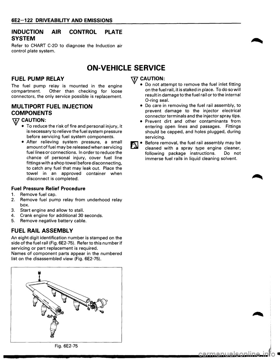
An eight digit identification number is stamped on the
side
ofthe fuel rail (Fig. 6E2-75). Refer to this number if
servicing or part replacement is required.
Names
of component parts appear in the numbered
list on the disassembled view (Fig. 6E2-75).
'fCAUTION:
• Do not attempt to remove the fuel inlet fitting
on the
fuel rail, it is staked in place. To do so will
result
in damage to the fuel rail or to the internal
0-ring seal.
•
Do care in removing the fuel rail assembly, to
prevent damage to the injector
electrical
connector terminals and the injector spray tips.
• Prevent dirt and other contaminants from
entering open lines and passages. Fittings
should be capped, and holes plugged, during
servicing.
Before
removal, the fuel rail assembly may be
cleaned with a spray type engine cleaner,
following
package instructions. Do not
immerse fuel rails in liquid cleaning solvent.
Fig. 6E2-75
I'
---------------------'
•
Page 820 of 1928
6E2-124 DRIVEABILITV AND EMISSIONS
E) REMOVAL
Preparation: • Engine hood
• Battery negative cable
1.
Air cleaner assy
2.
Accelerator pedal cable
•
Disconnect from throttle body and cable
brackets.
3. Canister vacuum hose
• Disconnect from vacuum switch valve (VSV).
4. Vacuum booster hose
• Disconnect from Common chamber duct.
5. Connectors
• Disconnect idle air control valve, throttle
position sensor, manifold absolute pressure,
canister
VSV, exhaust gas recirculation (EGR)
VSV, intake air temperature and VSV.
6. High tension cable
• Remove from cylinder heads.
7. Electronic ignition (EI) module assy
• Disconnect 3 connector from El module.
• Remove 3 bolts from El bracket and El assy.
8.
Throttle body (TB)
• Remove 4 bolts from TB.
9. Vacuum hoses
• Disconnect canister VSV and EGR VSV vacuum
hose
from TB.
10. Fuel pressure control valve vacuum hose
• Disconnect from common chamber duct.
11.
PCV hose
• Disconnect from common chamber duct.
12.
Evaporate emission canister purge hose
• Disconnect from common chamber duct.
13.
EGR valve assy
• Remove 4 bolts from common chamber duct
and exhaust manifold.
14.
Common chamber duct
• Remove 4 bolts, 4 nuts and 3 duct bracket fixing
bolts.
• Remove ground cable fixing bolt from rear of
common chamber duct.
15.
Common chamber
• Remove 6 bolts and 2 nuts.
• Remove common chamber bracket fixing bolts
from rear of common chamber.
16. Fuel
hose
• Feed and return hose from fuel pipe and 2 fixing
bolts
from cylinder head. 17.
Fuel
rail assembly
• Remove fuel injector connector.
• Remove fuel rail fixing bolts.
• Remove fuel rail assy.
j .. !•l DISASSEMBL V
NOTE:
• If
an injector becomes separated from the rail and
remains in the cylinder head, both injector
0-ring
seals and the retainer clip must be replaced.
1.
Regulator attaching screw
2. Fuel pressure control valve assembly
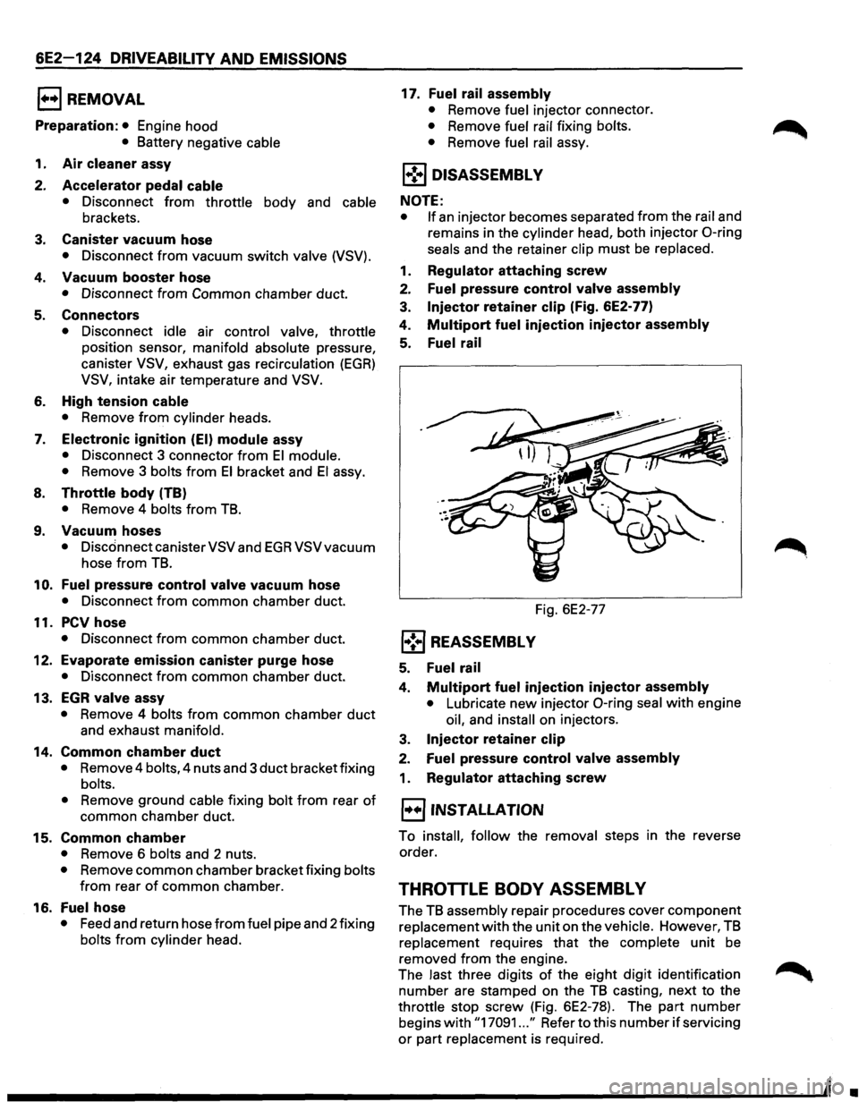
3. Injector retainer clip (Fig. 6E2-77)
4.
Multipart fuel injection injector assembly
5. Fuel rail
Fig. 6E2-77
l•! .. j REASSEMBL V
5. Fuel rail
4. Multipart fuel injection injector assembly
• Lubricate new injector 0-ring seal with engine
oil, and
install on injectors.
3.
Injector retainer clip
2. Fuel pressure control valve assembly
1. Regulator attaching screw
l·u·jiNSTALLATION
To install, follow the removal steps in the reverse
order.
THROTTLE BODY ASSEMBL V
The TB assembly repair procedures cover component
replacement
with the unit on the vehicle. However, TB
replacement requires that the complete unit be
removed from the engine.
The last three digits
of the eight digit identification
number are stamped on the
TB casting, next to the
throttle stop screw (Fig. 6E2-78). The part number
begins
with "17091 ... " Refer to this number if servicing
or part replacement is required.
•