battery ISUZU TROOPER 1995 Workshop Manual
[x] Cancel search | Manufacturer: ISUZU, Model Year: 1995, Model line: TROOPER, Model: ISUZU TROOPER 1995Pages: 1928
Page 866 of 1928
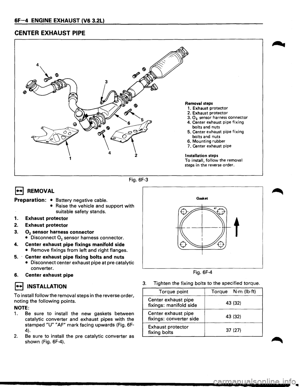
&F-4 ENGINE EXHAUST (V6 3.2L)
CENTER EXHAUST PIPE
4
1
Fig. 6F-3
E3 REMOVAL
Preparation: • Battery negative cable.
• Raise the vehicle and support with
suitable safety stands.
1. Exhaust protector
2. Exhaust protector
3. 02 sensor harness connector
• Disconnect 02 sensor harness connector.
4. Center exhaust pipe fixings manifold side
• Remove fixings from left and right flanges.
5. Center exhaust pipe fixing bolts and nuts
• Disconnect center exhaust pipe at pre catalytic
converter.
6. Center exhaust pipe
Removal steps 1. Exhaust protector
2. Exhaust protector
3.
02 sensor harness connector
4. Center exhaust pipe fixing
bolts and nuts
5. Center exhaust pipe fixing
bolts and nuts
6. Mounting rubber
7. Center exhaust pipe
Installation steps
To install, follow the removal
steps in the reverse order.
Gasket
t
Fig. 6F-4
1••1 INSTALLATION 3. Tighten the fixing bolts to the specified torque.
To
install follow the removal steps in the reverse order,
noting the
following points.
NOTE:
1. Be sure to install the new gaskets between
catalytic converter and exhaust pipes
with the
stamped
"U" "AF" mark facing upwards (Fig. 6F-
4).
2. Be sure to install the pre catalytic converter as
shown (Fig. 6F-4). Torque
point
Center exhaust pipe
fixings: manifold side
Center exhaust pipe
fixings: converter side
Exhaust protector
fixing bolts Torque
N·m
(lb·ft)
43 (32)
43 (32)
37 (27)
Page 867 of 1928
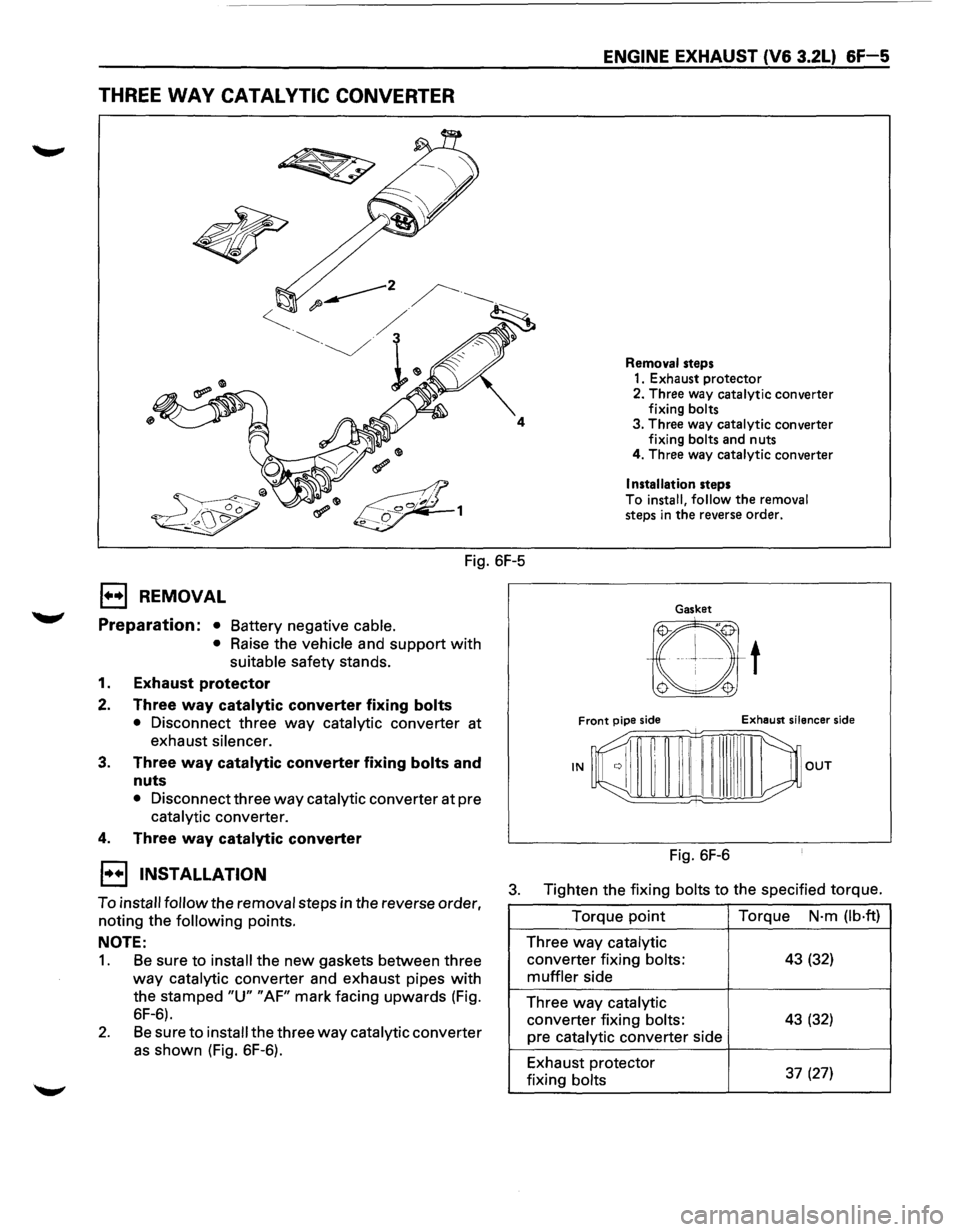
THREE WAY CATALYTIC CONVERTER
Fig. 6F-5
1••1 REMOVAL
Preparation: • Battery negative cable.
•
Raise the vehicle and support with
suitable safety stands.
1. Exhaust protector
2. Three way catalytic converter fixing bolts
• Disconnect three way catalytic converter at
exhaust
silencer.
3. Three way catalytic converter fixing bolts and
nuts
• Disconnect three way catalytic converter at pre
catalytic converter.
4. Three way catalytic converter
ENGINE EXHAUST (V6 3.2L) &F-5
Removal steps
1. Exhaust protector
2. Three way catalytic converter
fixing
bolts 3. Three way catalytic converter
fixing bolts and nuts
4. Three way catalytic converter
Installation steps
To
install, follow the removal steps in the reverse order.
Gasket
t
Front pipe side Exhaust silencer side
--;::;;;=;;:::;;=;;:::;;±:;;:~mn=i:'--
IN OUT
Fig. 6F-6
1••1 INSTALLATION
To install follow the removal steps in the reverse order,
noting the
following points.
3. Tighten the fixing bolts to the specified torque.
NOTE:
1. Be sure to install the new gaskets between three
way catalytic converter and exhaust pipes with
the stamped "U" "AF" mark facing upwards (Fig.
6F-6).
2. Be sure to install the three way catalytic converter
as shown (Fig. 6F-6). Torque
point
Three way catalytic
converter
fixing bolts:
muffler side
Three
way catalytic
converter fixing bolts:
pre catalytic converter side
Exhaust protector
fixing
bolts
Torque N·m (lb·ft)
43 (32)
43 (32)
37
(27)
Page 868 of 1928
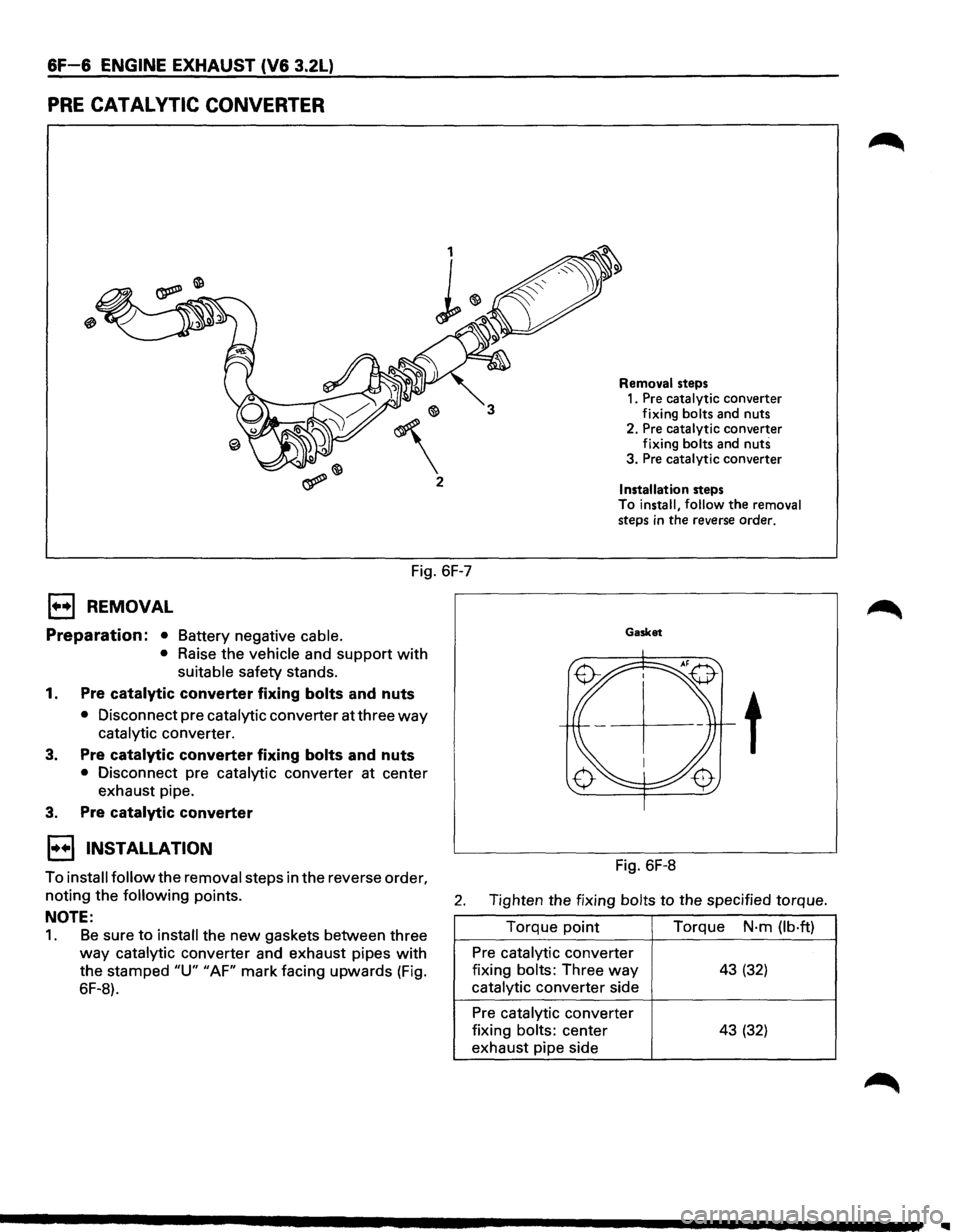
6F-6 ENGINE EXHAUST (V6 3.2L)
PRE CATAL VTIC CONVERTER
2
Fig. 6F-7
1••1 REMOVAL
Preparation: • Battery negative cable.
•
Raise the vehicle and support with
suitable safety stands.
1. Pre catalytic converter fixing bolts and nuts
• Disconnect pre catalytic converter at three way
catalytic converter.
3. Pre catalytic converter fixing bolts and nuts
• Disconnect pre catalytic converter at center
exhaust pipe.
3. Pre catalytic converter
1••1 INSTALLATION
Removal steps
1. Pre catalytic converter
fixing bolts and nuts
2. Pre catalytic converter
fixing bolts and
nuts 3. Pre catalytic converter
Installation steps To install, follow the removal
steps in the reverse order.
Gasket
t
Fig. 6F-8
To install follow the removal steps in the reverse order,
noting the following points. 2. Tighten the fixing bolts to the specified torque.
NOTE:
1. Be sure to install the new gaskets between three
way catalytic converter and exhaust pipes with
the stamped "U" "AF" mark facing upwards (Fig.
6F-8). Torque
point
Pre catalytic converter
fixing
bolts: Three way
catalytic converter side
Pre catalytic converter
fixing
bolts: center
exhaust pipe side Torque
N·m
(lb·ft)
43 (32)
43 (32)
Page 869 of 1928
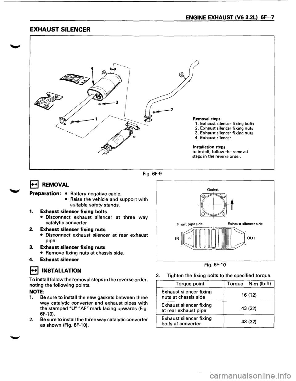
EXHAUST SILENCER
4
Fig. 6F-9
E) REMOVAL
Preparation: •
Battery negative cable.
• Raise the vehicle and support with
suitable safety stands.
1. Exhaust silencer fixing bolts
• Disconnect exhaust silencer at three way
catalytic converter
2. Exhaust silencer fixing nuts
• Disconnect exhaust silencer at rear exhaust
pipe
3. Exhaust silencer fixing nuts
• Remove fixing nuts at chassis side.
4. Exhaust silencer
ENGINE EXHAUST (V6 3.2L) 6F-7
Removal steps
1. Exhaust silencer fixing bolts 2. Exhaust silencer fixing nuts
3. Exhaust silencer fixing nuts
4. Exhaust silencer
Installation
steps to install, follow the removal steps in the reverse order.
Gasket
Fig. 6F-10
1••1 INSTALLATION
To install follow the removal steps in the reverse order,
noting the following points.
3. Tighten the fixing bolts to the specified torque.
NOTE:
1. Be sure to install the new gaskets between three
way catalytic converter and exhaust pipes with
the stamped "U" "AF" mark facing upwards (Fig.
SF-10).
2. Be sure to install the three way catalytic converter
as shown (Fig. SF-10).
Torque point
Exhaust silencer fixing
nuts at chassis side
Exhaust silencer fixing
at rear exhaust pipe
Exhaust silencer fixing
bolts
at converter Torque
N·m
(lb·ft)
16 (12)
43 (32)
43 (32)
Page 870 of 1928
6F-8 ENGINE EXHAUST (V6 3.2L)
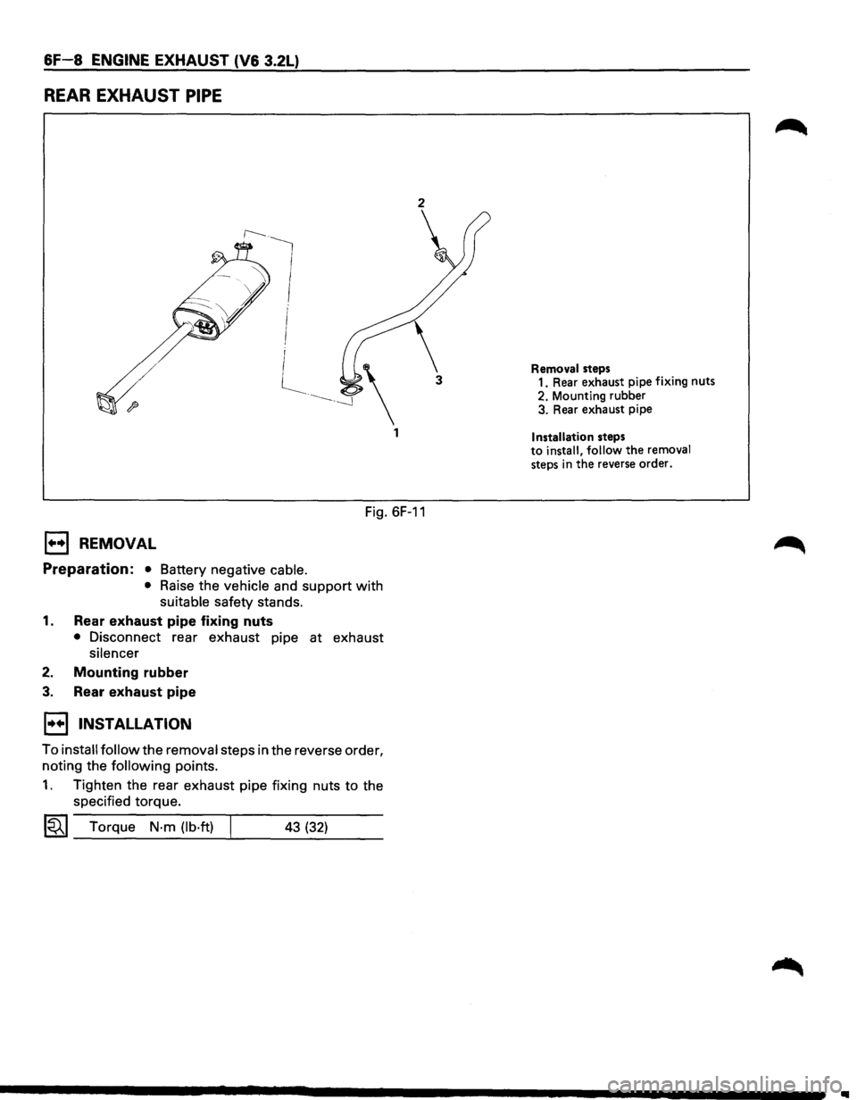
REAR EXHAUST PIPE
2
Fig. 6F-11
1+•1 REMOVAL
Preparation: • Battery negative cable.
• Raise the vehicle and support with
suitable safety stands.
1. Rear exhaust pipe fixing nuts
• Disconnect rear exhaust pipe at exhaust
silencer
2. Mounting rubber
3. Rear exhaust pipe
1••1 INSTALLATION
To install follow the removal steps in the reverse order,
noting the
following points.
1. Tighten the rear exhaust pipe fixing nuts to the
specified torque.
1«1 Torque N-m (lb·ft) 43 (32)
Removal steps 1. Rear exhaust pipe fixing nuts
2. Mounting rubber
3. Rear exhaust pipe
Installation steps to install, follow the removal steps in the reverse order.
1111
Page 871 of 1928
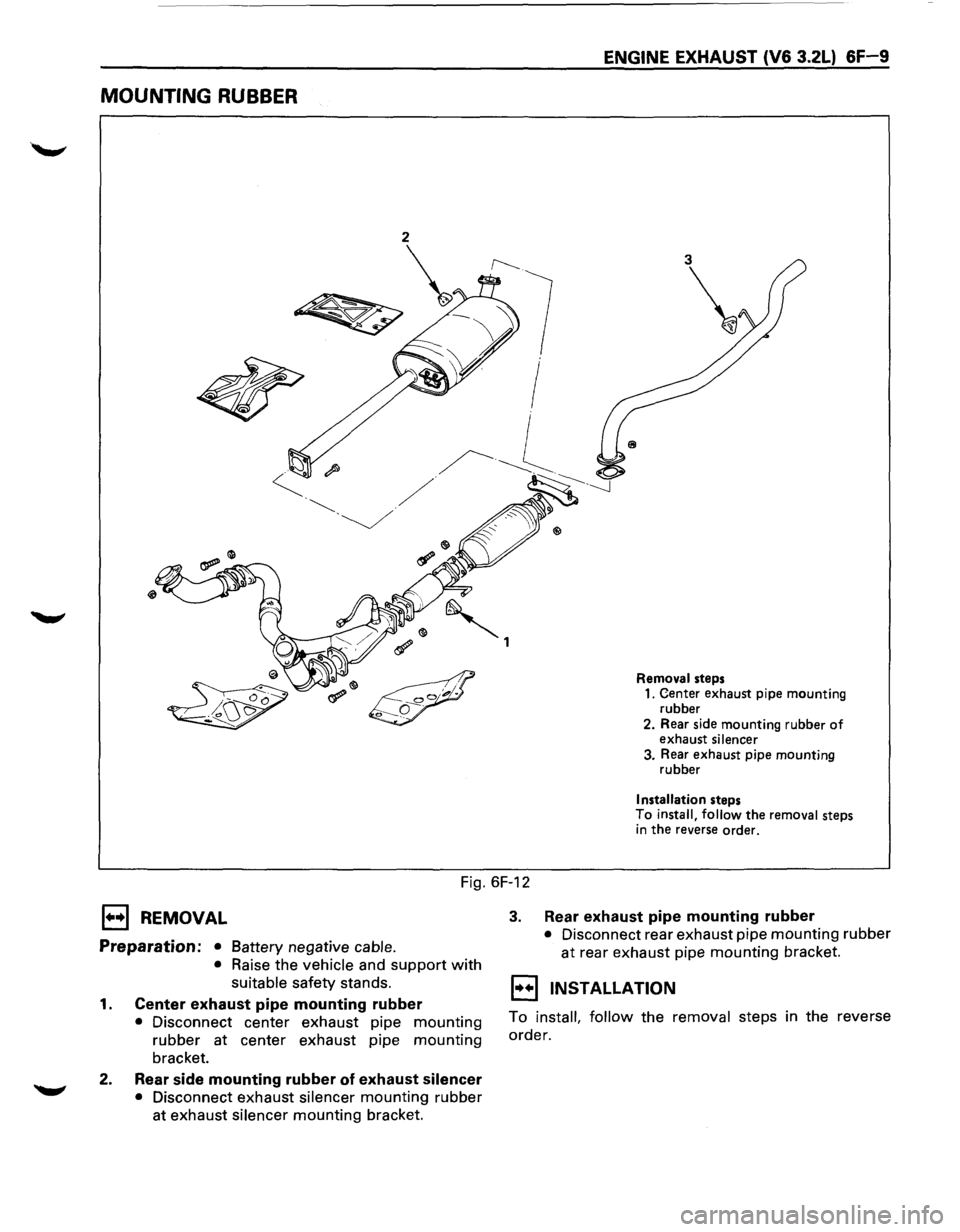
MOUNTING RUBBER
ENGINE EXHAUST (V6 3.2L) 6F-9
3
Removal steps 1. Center exhaust pipe mounting
rubber
2. Rear side mounting rubber
of exhaust silencer 3. Rear exhaust pipe mounting
rubber
Installation steps
To install, follow the removal steps in the reverse order.
Fig. 6F-12
E) REMOVAL
Preparation: • Battery negative cable.
• Raise the vehicle and support with
suitable safety stands.
1. Center exhaust pipe mounting rubber
• Disconnect center exhaust pipe mounting
rubber at center exhaust pipe mounting
bracket.
2. Rear side mounting rubber of exhaust silencer
• Disconnect exhaust silencer mounting rubber
at exhaust silencer mounting bracket.
3. Rear exhaust pipe mounting rubber
• Disconnect rear exhaust pipe mounting rubber
at rear exhaust pipe mounting bracket.
1••1 INSTALLATION
To install, follow the removal steps in the reverse
order.
Page 876 of 1928
•
"'Tl c3' -..J )> I "'
~ )
DASH
BOARD
DISPLA
V
*
*
*
*
ATF
WARNING
LAMP
CHECK
TRANS
LAMP
POWER DRIVE MODE LAMP WINTER DRIVE MODE LAMP
~----------------
SHIFT INDICATOR
LAMP
COMPENSATION
FOR
ENGINE
LOAD
AIR CONDITIONING SWITCH
TI
DRIVER'S
INPUT
liJ
MANUAL
SELECTOR
~
KICK-DOWN SWITCH
" ~
BRAKE
SWITCH
*
(AfT
SHIFT INDICATOR)
CONTROL
UNIT
---
' ---
I-------------,
il
PUSH BUTTON
FOR
NORMALJPOWER
DRIVE MODE
ON-BOARD DIAGNOSTIC
j4
.. ,
..
l__l--1 L_-$-L_g
ENGINE CONTROL
MODULE
(ECM)
_ IGNITION
CONTROL
I
MODULE
i
THROTTLE POSITION
SENSOR
ENGINE SPEED SENSOR
l
I
I -
ENGINE COOLANT TEMPERATU~,_.TCH
)
I +12 IGNITION
• •
TRANSMISSION
CONTROL MODULE
(TCM)
j
L I
BATTERY
)
--
~
'
5SOLENOID VALVES
il
-·----·
___.
u
PUSH BUTTON
FOR
WINTER DRIVE MODE
OTHERS
OVERDRIVE
OFF
SIGNAL
(CRUISE CONTROLLER)
ABS
SIGNAL
(ABS CONTROLLER)
f.-
n_
VEHICLE SPEED
SENSOR
f-
/
ATF TEMPERATURE SENSOR
L__ L__
[PRNDJ2L
I MODE SWITCH
-
m
.....
r-
)>
m
I
(")
..;=...
-t
)>
;::g 0
c:
2
-1
-
0
(")
s:
(")
~
0
-
2
n
-t
-1
;::g
:a
0
)> z
r-
en
c
s:
:;
(i)
C)
en
~
0 z
3:
-..;=... r-w 0 I !!!
)
Page 895 of 1928
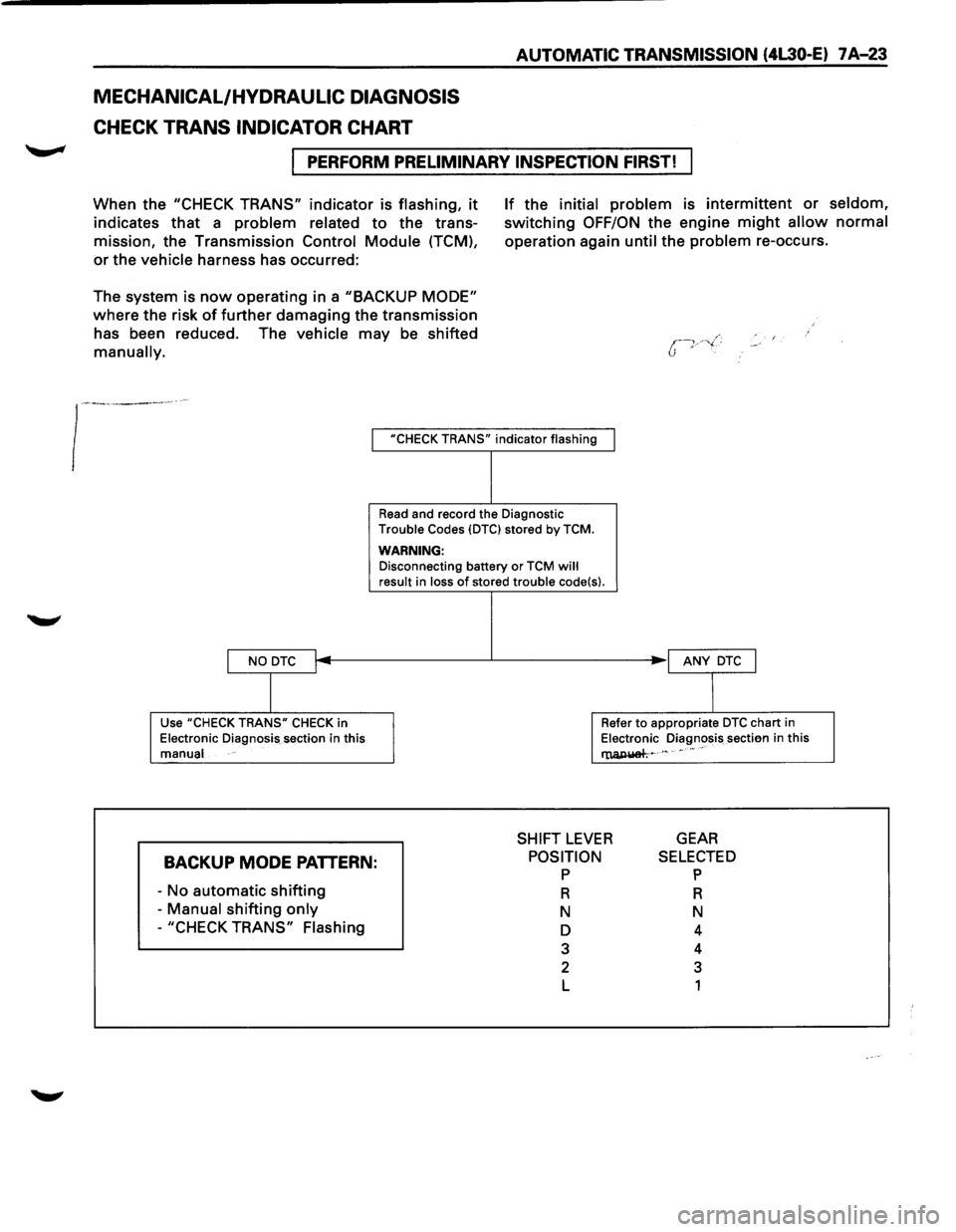
MECHANICAL/HYDRAULIC DIAGNOSIS
CHECK TRANS INDICATOR CHART
AUTOMATIC TRANSMISSION (4L30-E) 7 A-23
I PERFORM PRELIMINARY INSPECTION FIRST!
When the "CHECK TRANS" indicator is flashing, it
indicates that a problem related to the trans
mission, the Transmission Control
Module (TCM),
or the vehicle harness has occurred:
The system is
now operating in a "BACKUP MODE"
where the risk of further damaging the transmission
has been reduced. The vehicle may be shifted
manually.
If the initial problem is intermittent or seldom,
switching OFF/ON the engine might allow normal
operation again until the problem re-occurs.
I "CHECK TRANS" indicator flashing
I NO DTC I
I
Use "CHECK TRANS" CHECK in
Electronic Diagnosis section in this
manual
BACKUP MODE PATTERN:
-No automatic shifting
- Manual shifting only
-"CHECK TRANS" Flashing
Read and record the Diagnostic
Trouble Codes {DTCI stored by TCM.
WARNING: Disconnecting battery or TCM will result in loss of stored trouble code{s).
I ANY DTC J
I
Refer to appropriate DTC chart in
Electronic Diagnosis sectien in this
l'lUl,IUiah~ c " • •• "
SHIFT LEVER GEAR
POSITION p
R
N
D
3
2
L
SELECTED p
R
N
4
4
3
1
Page 920 of 1928
7 A-48 AUTOMATIC TRANSMISSION (4L30-E)
"CHECK TRANS" CHECK
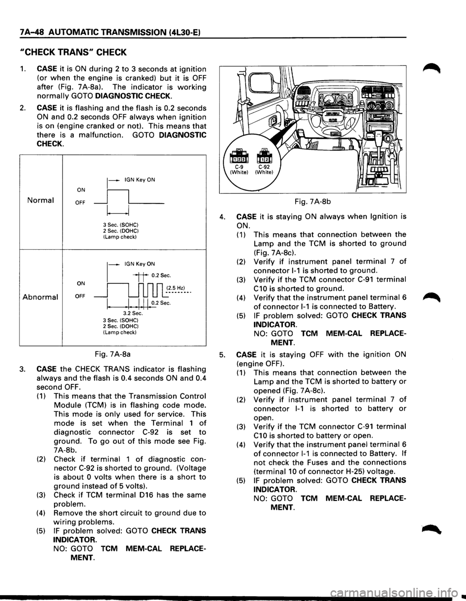
1. CASE it is ON during 2 to 3 seconds at ignition
(or when the engine is cranked) but it is OFF
after (Fig. 7A-8a). The indicator is working
normally GOTO DIAGNOSTIC CHECK.
2. CASE it is flashing and the flash is 0.2 seconds
ON and 0.2 seconds OFF always when ignition
is on (engine cranked or not). This means that
there is a malfunction. GOTO DIAGNOSTIC
CHECK.
Normal
Abnormal
~-IGN Key ON
ON
II
OFF __j l___
~
3 Sec. (SOHC) 2 Sec. (OOHC) (Lamp check)
1-
IGN Key ON
il 0.2Sec.
oN 11 n n n ~~--s_ ~~)-_. OFF __j u u u l:
I. .I. .1.11. 0.2
Sec.
3.2 Sec. 3 Sec. (SOHC) 2 Sec. (OOHC) (Lamp check)
Fig. 7A-8b
4. CASE it is staying ON always when Ignition is
ON.
(1) This means that connection between the
Lamp and the TCM is shorted to ground
(Fig. 7 A-8c).
(2) Verify if instrument panel terminal 7 of
connector 1-1 is shorted to ground.
(3) Verify if the TCM connector C-91 terminal
C10 is shorted to ground.
(4) Verify that the instrument panel terminal 6
of connector 1-1 is connected to Battery.
(5) IF problem solved: GOTO CHECK TRANS
INDICATOR.
NO: GOTO TCM MEM-CAL REPLACE
MENT.
Fig. 7A-8a 5. CASE it is staying OFF with the ignition ON
(engine OFF). 3. CASE the CHECK TRANS indicator is flashing
always and the flash is 0.4 seconds ON and 0.4
second OFF.
(1) This means that the Transmission Control
Module (TCM) is in flashing code mode.
This mode is only used for service. This
mode is set when the Terminal 1 of
diagnostic connector C-92 is set to
ground. To go out of this mode see Fig.
7A-8b.
(2) Check
if terminal 1 of diagnostic con
nector C-92 is shorted to ground. (Voltage
is
about 0 volts when there is a short to
ground instead of 5 volts).
(3) Check if TCM terminal 016 has the same
problem.
(4) Remove the short circuit to ground due to
wiring problems.
(5) IF problem solved: GOTO CHECK TRANS
INDICATOR.
NO: GOTO TCM MEM-CAL REPLACE
MENT.
(1) This means that connection between the
Lamp and the TCM is shorted to battery or
opened (Fig. 7 A-8c).
(2) Verify if instrument panel terminal 7 of
connector 1-1 is shorted to battery or
open.
(3)
Verify if the TCM connector C-91 terminal
C1 0 is shorted to battery or open.
(4)
Verify that the instrument panel terminal 6
of connector 1-1 is connected to Battery. If
not check the Fuses and the connections
(terminal 10 of connector H-25) voltage.
(5) IF problem solved: GOTO CHECK TRANS
INDICATOR.
NO: GOTO TCM MEM-CAL REPLACE
MENT.
Page 924 of 1928
7A..J52 AUTOMATIC TRANSMISSION (4l30-E)
TECH1 CONNECTION
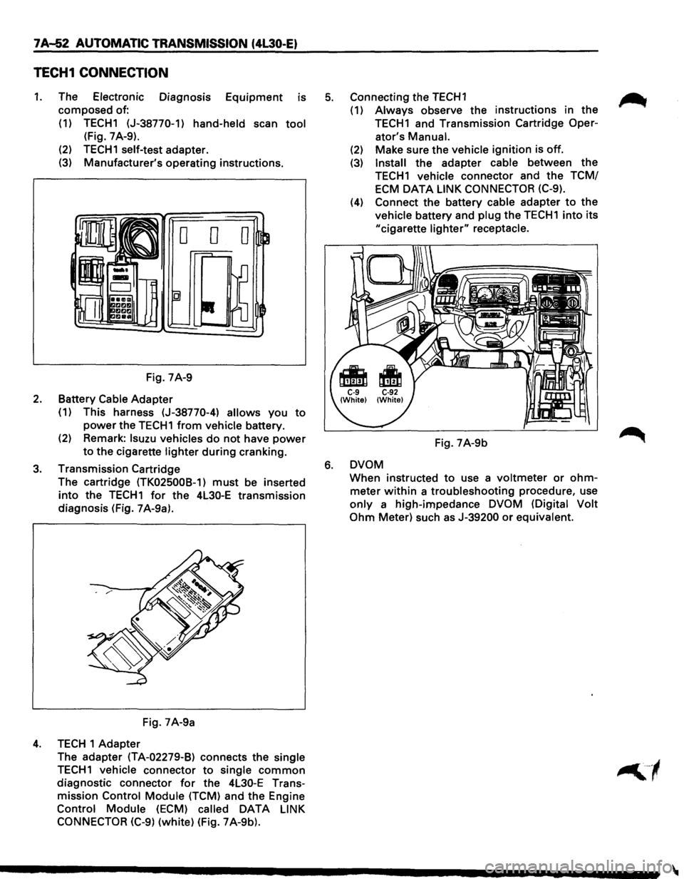
1. The Electronic Diagnosis Equipment is
composed of:
(1) TECH1 (J-38770-1)
hand-held scan tool
(Fig. 7 A-9).
(2)
TECH1 self-test adapter.
(3) Manufacturer's operating instructions.
Fig. 7A-9
2. Battery Cable Adapter
(1) This harness (J-38770-4) allows you to
power the TECH1 from vehicle battery.
(2) Remark:
lsuzu vehicles do not have power
to the cigarette lighter during cranking.
3. Transmission Cartridge
The cartridge
(TK025008-1) must be inserted
into the TECH1 for the 4L30-E transmission
diagnosis (Fig. 7 A-9a).
Fig. 7A-9a
4. TECH 1 Adapter
The adapter
(TA-02279-B) connects the single
TECH1 vehicle connector to single common
diagnostic connector for the 4L30-E Trans
mission
Control Module (TCM) and the Engine
Control Module (ECM) called DATA LINK
CONNECTOR (C-9)
(white) (Fig. 7A-9b).
5. Connecting the TECH1 ~
(1) Always observe the instructions in the
TECH1 and Transmission Cartridge Oper-
ator's
Manual.
(2) Make sure the vehicle ignition is off.
(3) Install the adapter cable between the
TECH1 vehicle connector and the TCM/
ECM
DATA LINK CONNECTOR (C-9).
(4) Connect the battery cable adapter to the
vehicle battery and plug the TECH1 into its
"cigarette lighter" receptacle.
Fig. 7A-9b
6. DVOM
When instructed to use a voltmeter or ohm
meter within a troubleshooting procedure, use
only a high-impedance DVOM (Digital Volt
Ohm
Meter) such as J-39200 or equivalent.