clutch ISUZU TROOPER 1995 Workshop Manual
[x] Cancel search | Manufacturer: ISUZU, Model Year: 1995, Model line: TROOPER, Model: ISUZU TROOPER 1995Pages: 1928
Page 1133 of 1928
MANUAL TRANSMISSION 78-43
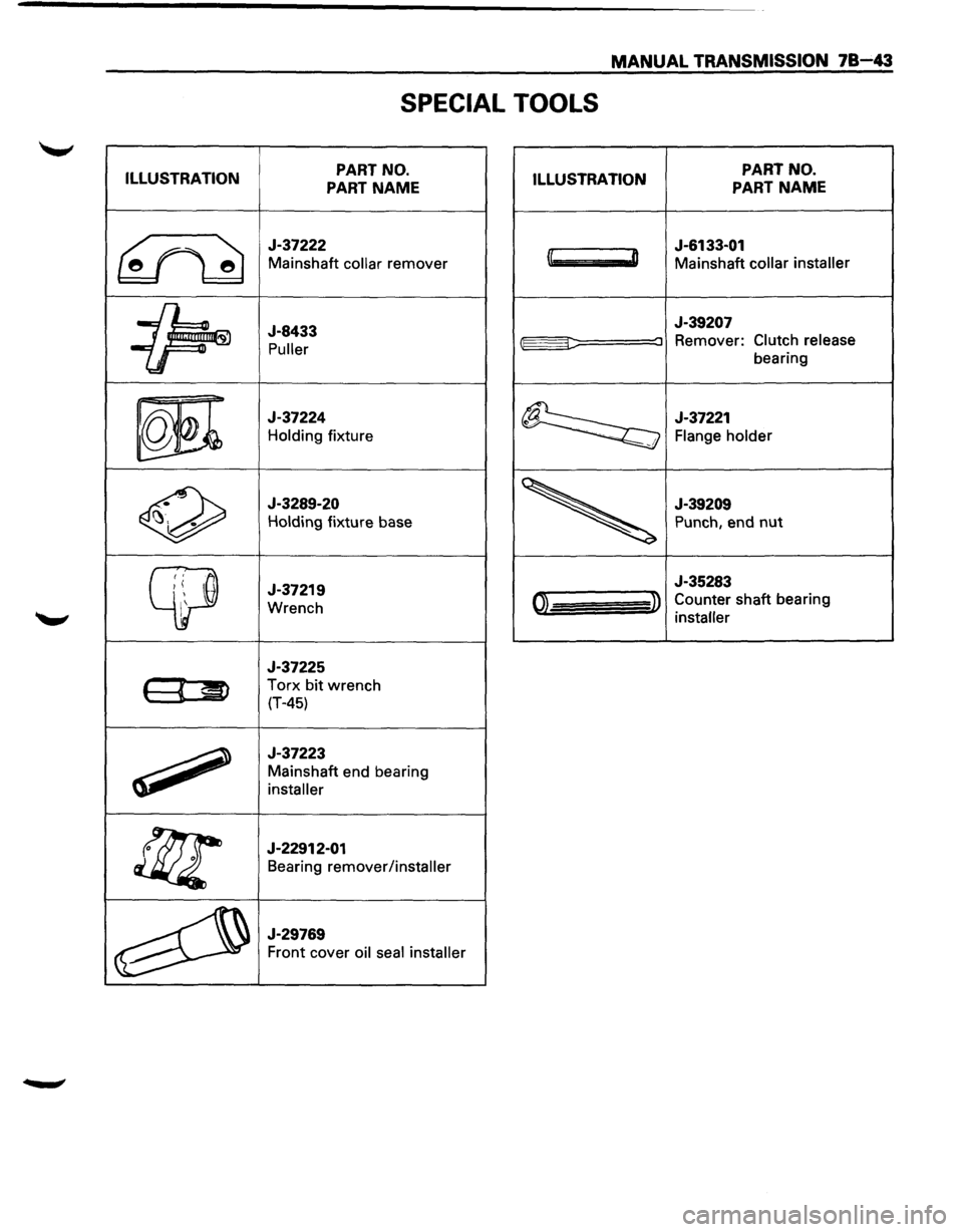
SPECIAL TOOLS
ILLUSTRATION PART
NO.
PART NAME ILLUSTRATION PART
NO.
PART NAME
~
J-37222
Mainshaft collar remover
J-6133-01
l~ D Mainshaft collar installer
~
J-8433
Puller
J-39207
::::: :J Remover: Clutch release
bearing
m
J-37224
Holding fixture ~
J-37221
Flange holder !.
0
J-3289-20
Holding fixture base
J-39209
Punch, end nut
~
J-37219
Wrench I '
J-35283
01 » Counter shaft bearing
installer
J-37225
( « ~ Torx bit wrench
(T-45)
~
J-37223
Mainshaft end bearing
installer
!f;r
J-22912-01
Bearing remover/installer
~
J-29769
Front cover oil seal installer
Page 1135 of 1928
CLUTCH 7C-1
SECTION 7C
CLUTCH
W CAUTION:
• When fasteners are removed, always reinstall them at the same location from which they were removed. If a
fastener needs to be
replaced, use the correct part number fastener for that application. If the correct part
number fastener is
not available, a fastener of equal size and strength (or stronger) may be used. Fasteners
that are not reused, and those requiring thread locking compound, will be called out. The correct torque
values must be used when installing fasteners that require torque. If the above conditions are not followed,
parts or system damage could result.
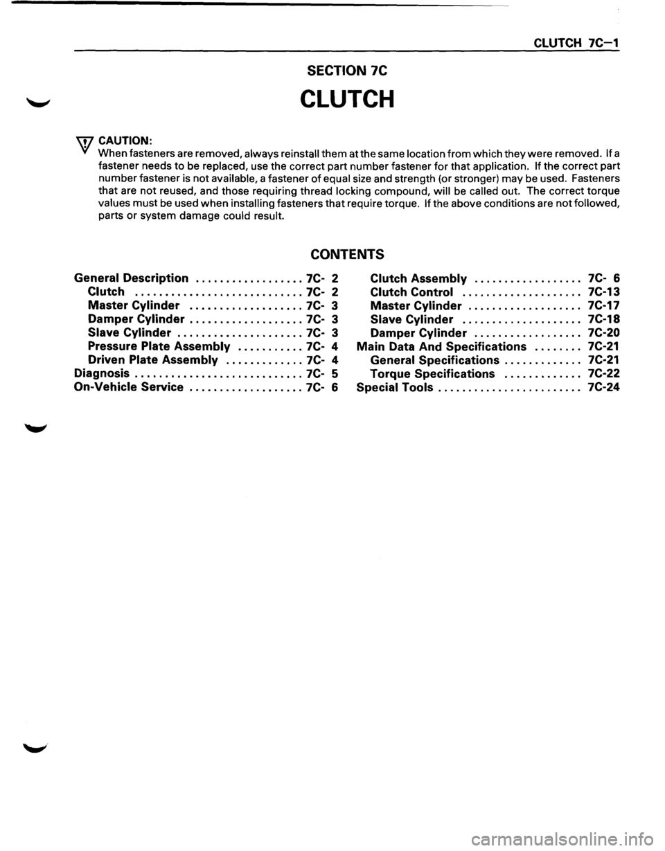
CONTENTS
General Description .................. 7C-2
Clutch ............................ 7C-2
Master
Cylinder ................... 7C- 3
Damper
Cylinder ................... 7C- 3
Slave Cylinder ..................... 7C-3
Pressure
Plate Assembly ........... 7C-4
Driven
Plate Assembly ............. 7C-4
Diagnosis
............................ 7C- 5
On-Vehicle Service ................... 7C-6
Clutch Assembly . .
. . . . . . . . . . . . . . . .
7C-6
Clutch Control . .
. . . . . . . . . . . . . . . . . .
7C-13
Master
Cylinder . .
. . . . . . . . . . . . . . . . .
7C-17
Slave Cylinder . .
. . . . . . . . . . . . . . . . . .
7C-18
Damper
Cylinder . .
. . . . . . . . . . . . . . . .
7C-20
Main
Data And Specifications . .
. . . . . .
7C-21
General Specifications
. . . . . . . . . . . . . 7C-21
Torque Specifications ............. 7C-22
Special Tools ........................ 7C-24
Page 1136 of 1928
7C-2 CLUTCH
GENERAL DESCRIPTION
CLUTCH
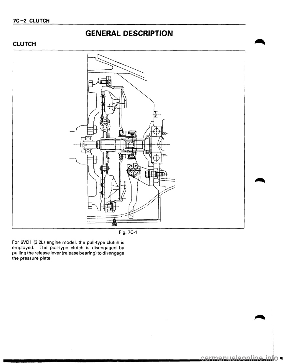
Fig. 7C-1
For 6VD1 (3.2L) engine model, the pull-type clutch is
employed. The pull-type clutch is disengaged by
pulling the release lever (release bearing) to disengage
the pressure
plate.
•
Page 1137 of 1928
CLUTCH 7C-3
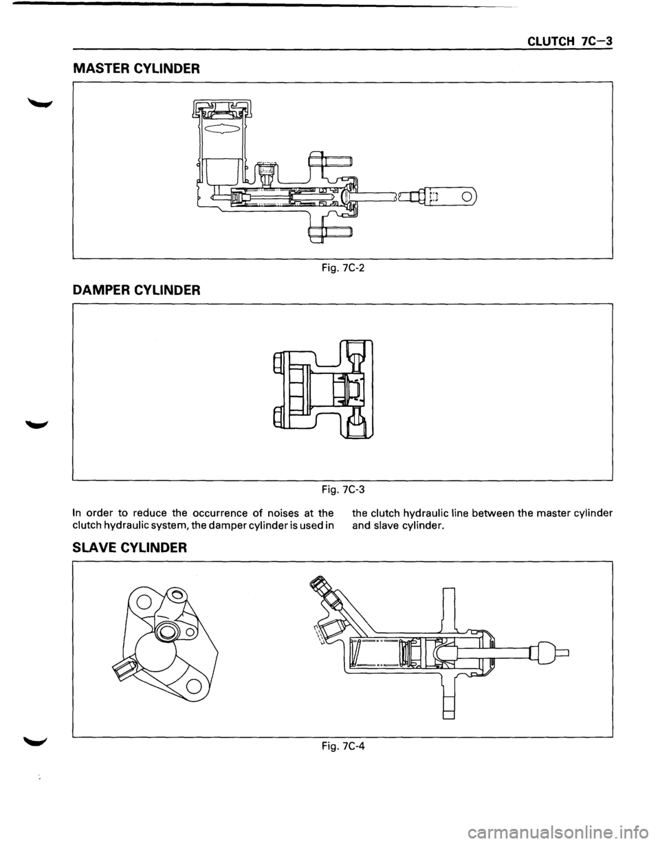
MASTER CYLINDER
Fig. 7C-2
DAMPER CYLINDER
Fig. 7C-3
In order to reduce the occurrence of noises at the
clutch hydraulic system, the damper cylinder is used in the
clutch
hydraulic line between the master cylinder
and slave cylinder.
SLAVE CYLINDER
Fig. 7C-4
Page 1138 of 1928
7C-4 CLUTCH
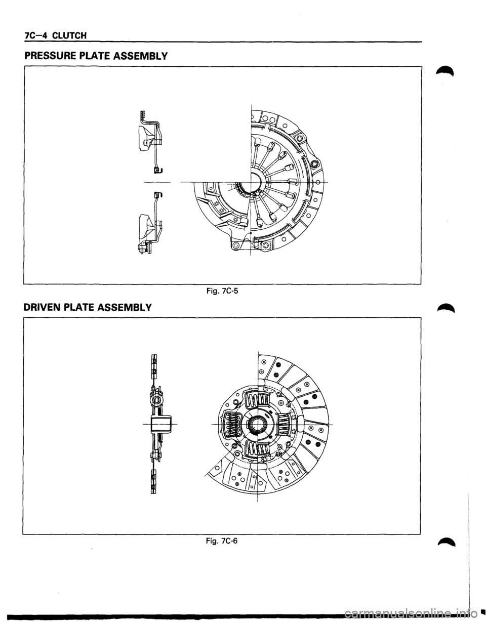
PRESSURE PLATE ASSEMBL V
Fig. 7C-5
DRIVEN PLATE ASSEMBL V
Fig. 7C-6
•
Page 1139 of 1928
CLUTCH 7C-5
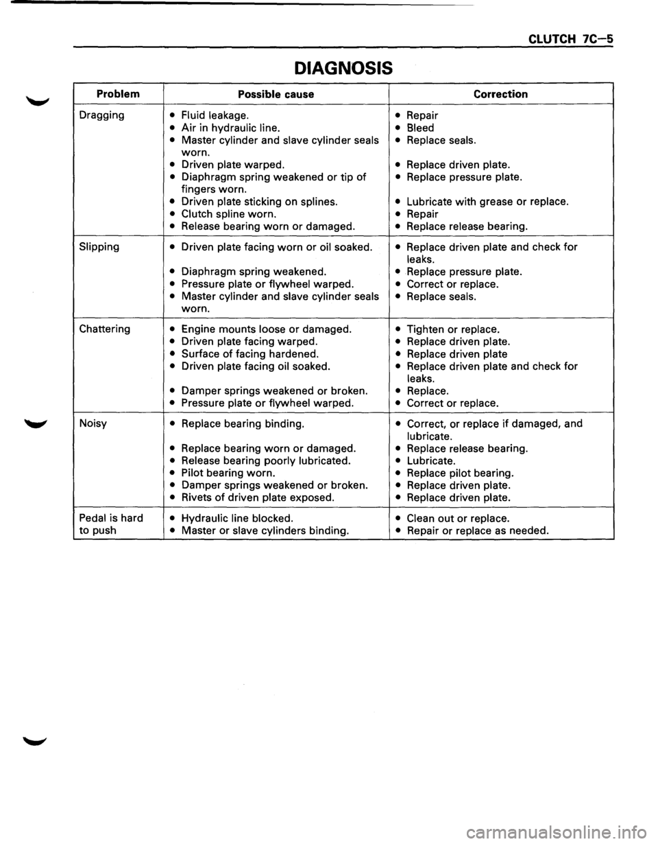
DIAGNOSIS
Problem Possible cause Correction
Dragging • Fluid leakage.
• Repair
• Air in hydraulic line.
• Bleed
•
Master cylinder and slave cylinder seals • Replace seals.
worn.
• Driven plate warped. • Replace driven plate.
•
Diaphragm spring weakened or tip of • Replace pressure plate.
fingers worn.
• Driven plate sticking on splines. • Lubricate with grease or replace.
• Clutch spline
worn. • Repair
• Release bearing worn or damaged. • Replace release bearing.
Slipping
• Driven plate facing worn or oil soaked. • Replace driven plate and check for
leaks.
•
Diaphragm spring weakened. • Replace pressure plate.
•
Pressure plate or flywheel warped. • Correct or replace.
•
Master cylinder and slave cylinder seals
• Replace seals.
worn.
Chattering
• Engine mounts loose or damaged. • Tighten or replace.
•
Driven plate facing warped. • Replace driven plate.
•
Surface of facing hardened. • Replace driven plate
•
Driven plate facing oil soaked. • Replace driven plate and check for
leaks.
•
Damper springs weakened or broken. • Replace.
•
Pressure plate or flywheel warped. • Correct or replace.
Noisy • Replace bearing binding. • Correct, or replace if damaged, and
lubricate.
• Replace
bearing worn or damaged. • Replace release bearing.
• Release bearing poorly lubricated.
• Lubricate.
• Pilot bearing worn. • Replace pilot bearing.
• Damper springs weakened or broken. • Replace driven plate.
•
Rivets of driven plate exposed. • Replace driven plate.
Pedal
is hard • Hydraulic line blocked.
• Clean out or replace.
to push • Master or slave cylinders binding. • Repair or replace as needed.
Page 1140 of 1928
7C-6 CLUTCH
ON-VEHICLE SERVICE
CLUTCH ASSEMBL V
6
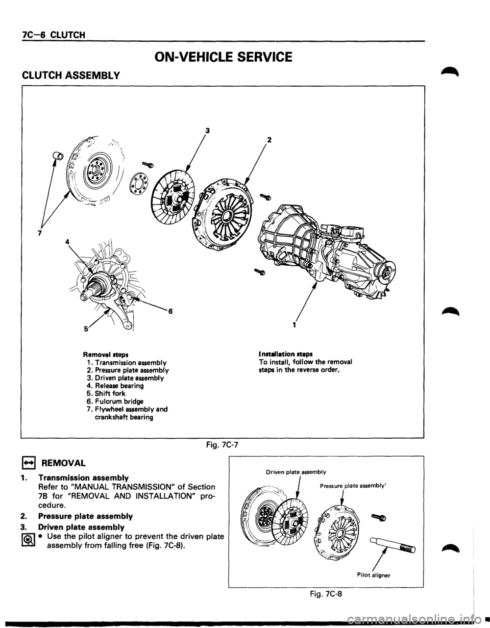
Removal steps
1••1 REMOVAL
1. Transmission assembly
2. Pressure plate assembly
3. Driven plate assembly 4. Release bearing 5. Shift fork
6. Fulcrum bridge
7. Flywheel assembly and
crankshaft bearing
1. Transmission assembly
3
Fig. 7C-7
Refer to "MANUAL TRANSMISSION" of Section
78
for "REMOVAL AND INSTALLATION" pro
cedure.
2. Pressure plate assembly
3. Driven plate assembly
li0\1 • Use the pilot aligner to prevent the driven plate
lSi~ assembly from falling free (Fig. 7C-8).
2
Installation steps
To install,
follow the removal steps in the reverse order.
Drivtm plate assembly
Pressure plate assembly'
Pilot aligner
Fig. 7C-8
•
Page 1141 of 1928
Pilot aligner: J-24547
• Mark the flywheel, clutch cover and pressure
plate lug for alignment when installing.
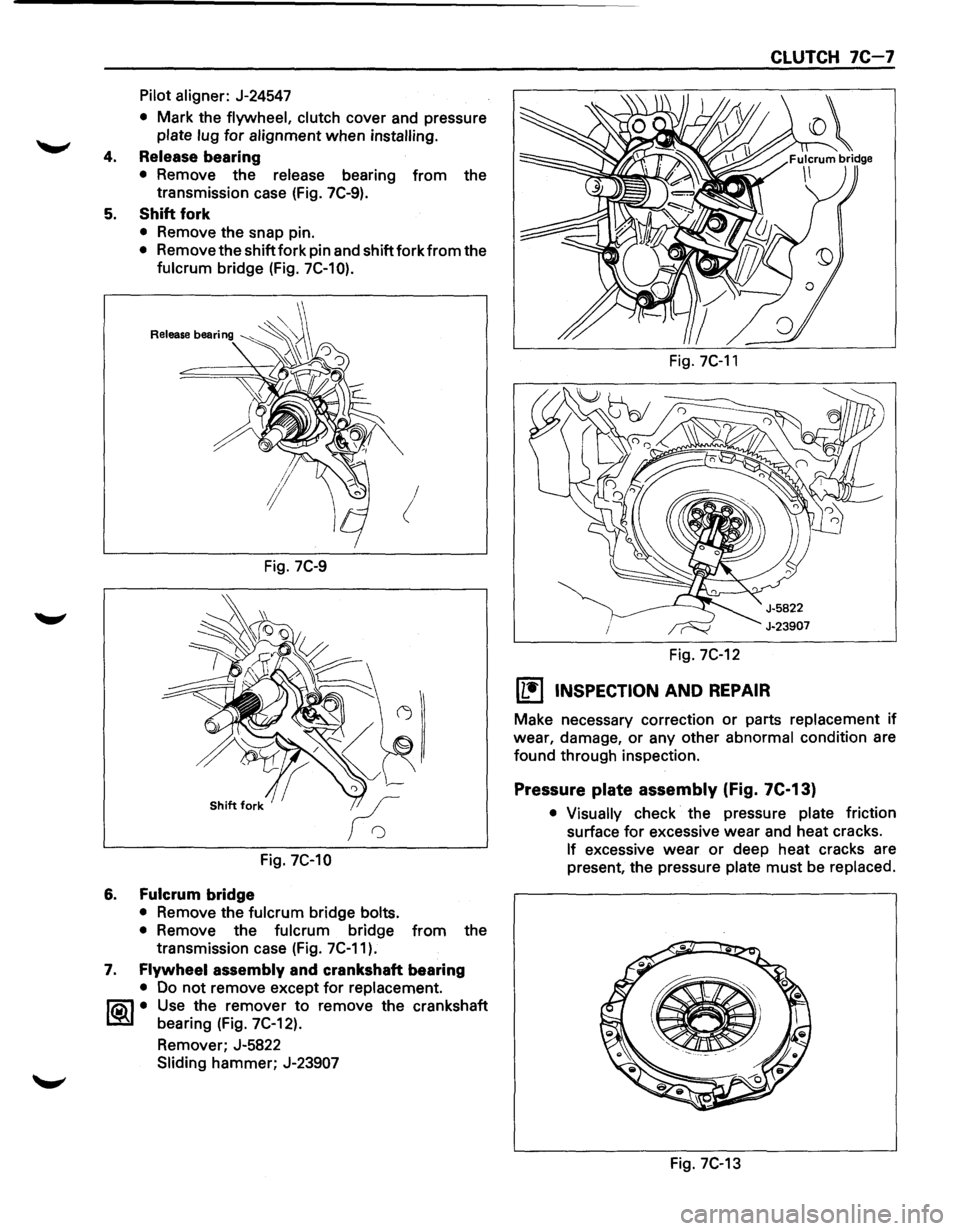
4. Release bearing
• Remove the release bearing from the
transmission case (Fig. 7C-9).
5. Shift fork
• Remove the snap pin.
• Remove the shift fork pin and shift fork from the
fulcrum bridge (Fig. 7C-10).
!
Fig. 7C-9
Fig. 7C-10
6. Fulcrum bridge
• Remove the fulcrum bridge bolts.
•
Remove the fulcrum bridge from the
transmission case (Fig. 7C-11).
7. Flywheel assembly and crankshaft bearing
• Do not remove except for replacement.
~~~· Use the remover to remove the crankshaft
bearing (Fig. 7C-12).
Remover; J-5822
Sliding hammer; J-23907
Fig. 7C-11
Fig. 7C-12
[L!j INSPECTION AND REPAIR
CLUTCH 7C-7
Make necessary correction or parts replacement if
wear, damage, or any other
abnormal condition are
found through inspection.
Pressure plate assembly (Fig. 7C-13)
• Visually check the pressure plate friction
surface
for excessive wear and heat cracks.
If excessive wear or deep heat cracks are
present, the pressure
plate must be replaced.
e ·---------
Fig. 7C-13
Page 1142 of 1928
7C-8 CLUTCH
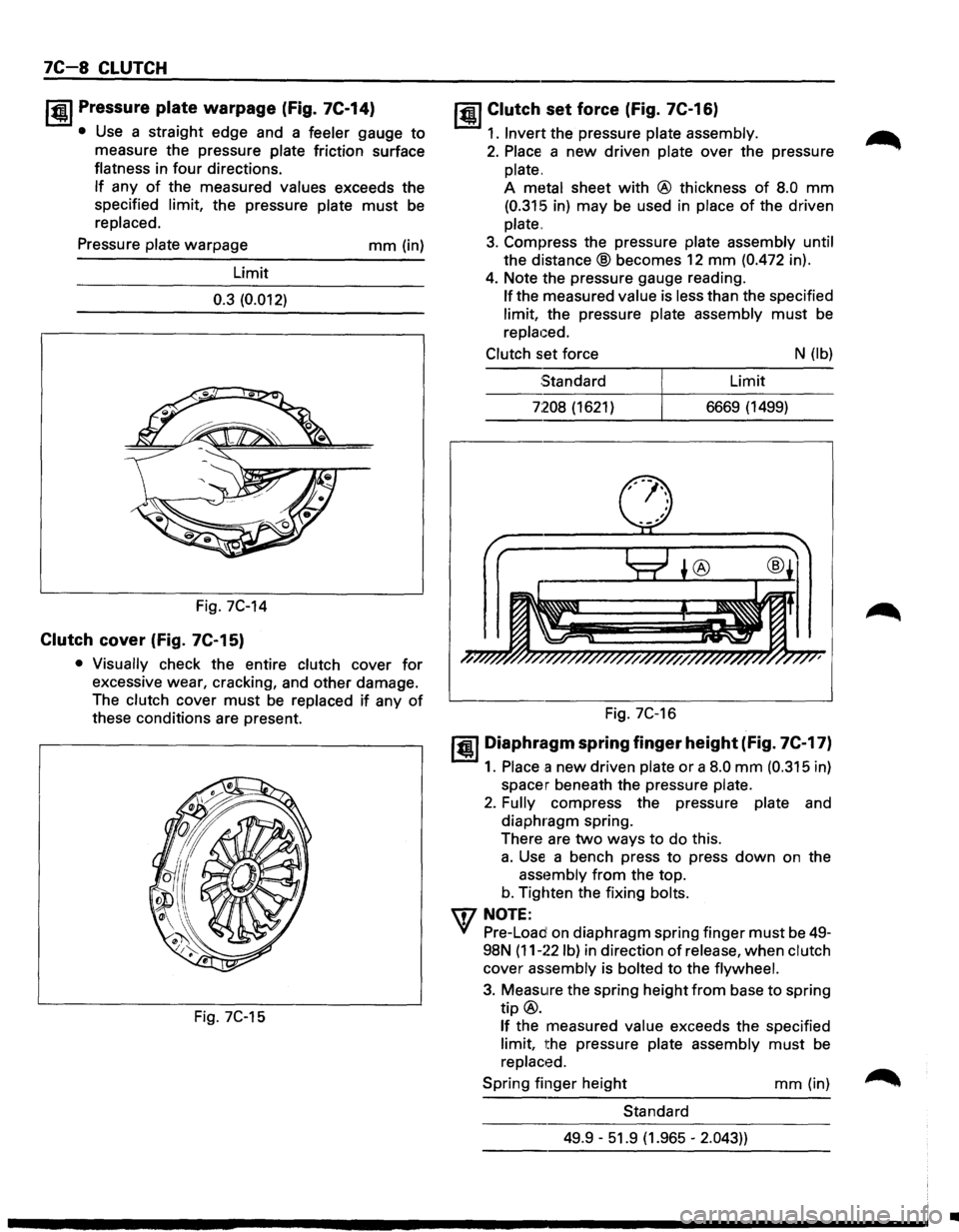
I~U Pressure plate warpage (fig. 7C-14)
• Use a straight edge and a feeler gauge to
measure the pressure plate friction surface
flatness in
four directions.
If any of the measured values exceeds the
specified limit, the pressure plate
must be
replaced.
Pressure plate warpage
Limit
0.3 (0.012)
Fig. 7C-14
Clutch cover (fig. 7C-15)
mm (in)
• Visually check the entire clutch cover for
excessive wear, cracking, and other damage.
The clutch cover
must be replaced if any of
these conditions are present.
Fig. 7C-15
jQI Clutch set force (Fig. 7C-16)
1. Invert the pressure plate assembly.
2. Place a new driven plate over the pressure
plate.
A metal sheet
with @ thickness of 8.0 mm
(0.315 in) may be used in place of the driven
plate
..
3. Compress the pressure plate assembly until
the
distance® becomes 12 mm (0.472 in).
4. Note the pressure gauge reading.
If the measured value is less than the specified
limit, the pressure plate assembly
must be
replaced.
Clutch set force N (lb)
Standard Limit
7:208 (1621) 6669 (1499)
Fig. 7C-16
1•1 Diaphragm spring finger height (fig. 7C-17)
1. Place a new driven plate or a 8.0 mm (0.315 in)
spacer beneath the pressure plate.
2. Fully compress the pressure plate and
diaphragm spring.
There are
two ways to do this.
a. Use a bench press to press down on the
asst~mbly from the top.
b. Tighten the fixing bolts.
IDNOTE:
Yf Pre-Load on diaphragm spring finger must be 49-
98N
(11-~~2 lb) in direction of release, when clutch
cover
assembly is bolted to the flywheel.
3. Measure the spring height from base to spring
tip@.
If the measured value exceeds the specified
limit, the pressure plate assembly
must be
replaced.
Spring finger height
mm (in)
Standard
49.9 -51.9 (1.965 -
2.043))
•
Page 1143 of 1928
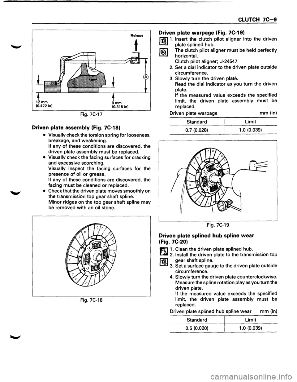
Fig. 7C-17
mm (0.315 in)
Driven plate assembly (Fig. 7C-18)
Release
t
• Visually check the torsion spring for looseness,
breakage, and weakening.
If any of these conditions are discovered, the
driven
plate assembly must be replaced.
• Visually check the facing surfaces for cracking
and excessive scorching.
Visually inspect the facing surfaces for the
presence
of oil or grease.
If any of these conditions are discovered, the
facing
must be cleaned or replaced.
• Check that the driven plate moves smoothly on
the transmission
top gear shaft spline.
Minor ridges on the top gear shaft spline may
be removed
with an oil stone.
Fig. 7C-18
CLUTCH 7C-9
Driven plate warpage (Fig. 7C-19)
l'fil1. Insert the clutch pilot aligner into the driven
1.!!!1 plate splined hub.
li5\l The clutch pilot aligner must be held perfectly
I.::2Y horizontal.
Clutch pilot
aligner; J-24547
2. Set a dial indicator to the driven plate outside
circumference.
3. Slowly turn the driven plate.
Read the dial indicator as you turn the driven
plate.
If
the measured value exceeds the specified
limit, the driven plate assembly must be
replaced.
Driven
plate warpage mm (in)
Standard Limit
0.7 (0.028) 1.0
(0.039)
Fig. 7C-19
Driven plate splined hub spline wear
(Fig.
7C-20)
E1 1. Clean the driven plate splined hub.
l...al 2. Install the driven plate to the transmission top
ffi1 gear shaft spline.
1.!!1 3. Set a surface gauge to the driven plate outside
circumference.
4. Slowly turn the driven plate counterclockwise.
Measure the
spline rotation play as you turn the
driven
plate.
If
the measured value exceeds the specified
limit, the driven plate assembly must be
replaced.
Driven
plate splined hub spline wear mm (in)
Standard Limit
0.5 (0.020) 1.0 (0.039)