ISUZU TROOPER 1995 Workshop Manual
Manufacturer: ISUZU, Model Year: 1995, Model line: TROOPER, Model: ISUZU TROOPER 1995Pages: 1928
Page 1781 of 1928
BODY 1Q-23
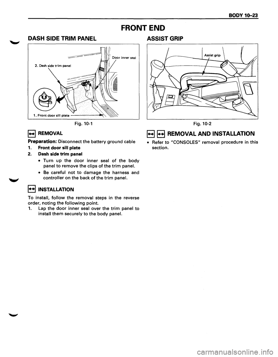
DASH SIDE TRIM PANEL
FRONT END
ASSIST GRIP
2. Dash side trim panel
Fig. 10-1
1++1 REMOVAL
Preparation: Disconnect the battery ground cable
1. Front door sill plate
2. Dash side trim panel
• Turn up the door inner seal of the body
panel to remove the clips of the trim panel.
•
Be careful not to damage the harness and
controller on the back of the trim panel.
I••! INSTALLATION
To install, follow the removal steps in the reverse
order,
noting the following point.
1. Lap the door inner seal over the trim panel to
install them securely to the body panel.
Fig. 10-2
B 8 REMOVAL AND INSTALLATION
• Refer to "CONSOLES" removal procedure in this
section.
Page 1782 of 1928
10-24 BODY
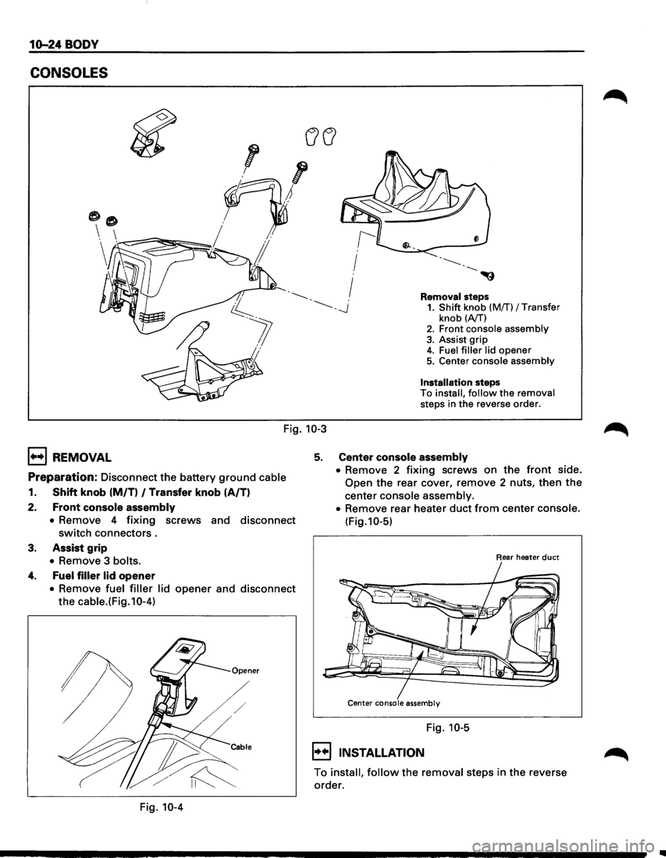
CONSOLES
Removal steps 1. Shift knob (Mff) I Transfer
knob (A/T) 2. Front console assembly
3. Assist grip 4. Fuel filler lid opener 5. Center console assembly
Installation steps
To install, follow the removal
steps in the reverse order.
Fig. 10-3
1+•1 REMOVAL
Preparation: Disconnect the battery ground cable
1. Shift knob (M/T) I Transfer knob (A/T)
2.
Front console assembly
• Remove 4 fixing screws and disconnect
switch connectors.
3. Assist grip
• Remove 3 bolts.
4. Fuel filler lid opener
• Remove fuel filler lid opener and disconnect
the cable.(Fig.10-4)
Fig. 10-4
5. Center console assembly
• Remove 2 fixing screws on the front side.
Open the rear cover, remove 2 nuts, then the
center console assembly.
•
Remove rear heater duct from center console.
(Fig.10-5)
Rear heater duct
Center console assembly
Fig. 10-5
I••IINSTALLATION
To install, follow the removal steps in the reverse
order.
Page 1783 of 1928
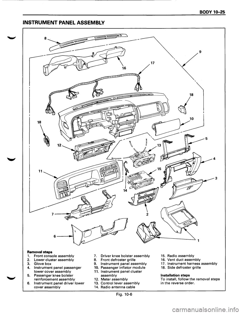
INSTRUMENT PANEL ASSEMBLY
18
11
Removal steps 1. Front console assembly 2. Lower cluster assembly 3. Glove box 4. Instrument panel passenger lower cover assembly
5. Passenger knee bolster reinforcement assembly 6. Instrument panel driver lower cover assembly
7. Driver knee bolster assembly 8. Front defroster grille 9. Instrument panel assembly
10. Passenger inflator module 11. Instrument panel cluster assembly 12. Meter assembly 13. Control lever assembly 14. Radio antenna cable
Fig. 10-6
17
BODY 10-25
9
3
1
15. Radio assembly 16. Vent duct assembly 17. Instrument harness assembly 18. Side defroster grille
Installation steps To install, follow the removal steps
in the reverse order.
Page 1784 of 1928
10-26 BODY
l••l REMOVAL
Caution:
• For precautions on installation or removal of
SRS -air bag system, refer to section 9J
"Supplemental Restraint System (SRS) -AIR
BAG".
Preparation: Disconnect battery ground cable
1. Front console assembly
•
Remove 4 fixing screws and disconnect
switch connectors .
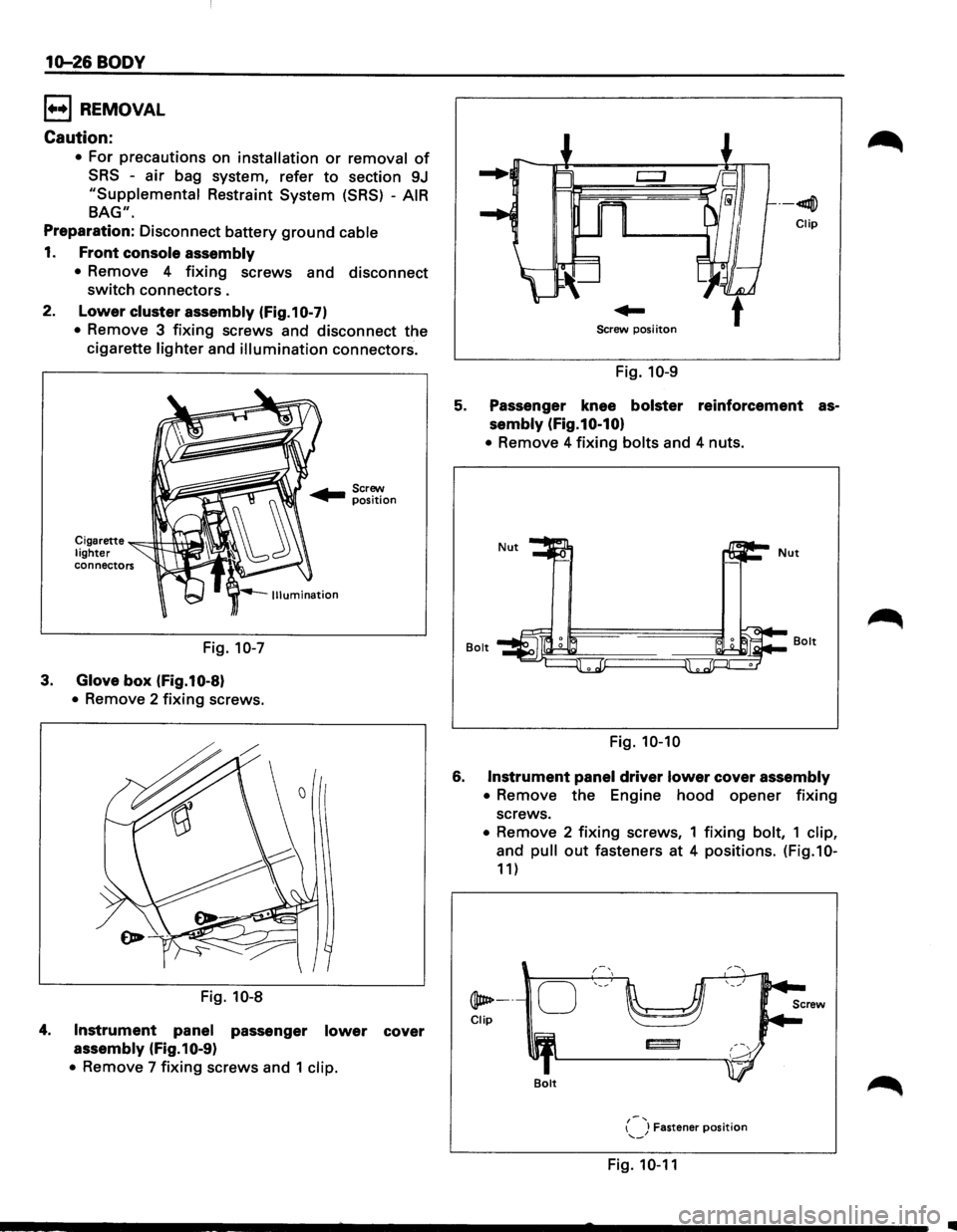
2. Lower cluster assembly (Fig.10-7)
• Remove 3 fixing screws and disconnect the
cigarette
lighter and illumination connectors.
Cigarette ~c--!H---1\.+.....,. lighter connectors
Fig. 10-7
3. Glove box (Fig.10-8)
• Remove 2 fixing screws.
Fig.
10-8
4. Instrument panel passenger lower cover
assembly (Fig.10-9)
• Remove 7 fixing screws and 1 clip.
--41llj])
Clip
Screw posi iton
Fig. 10-9
5. Passenger knee bolster reinforcement as
sembly (Fig.10-10)
• Remove 4 fixing bolts and 4 nuts.
Bolt
Fig. 10-10
6. Instrument panel driver lower cover assembly
•
Remove the Engine hood opener fixing
screws.
• Remove 2 fixing screws, 1 fixing bolt, 1 clip,
and pull out fasteners at 4 positions. (Fig.10-
11)
@ate----
Clip
Bolt
{-J Fastener position '--
Fig. 10-11
..
Page 1785 of 1928
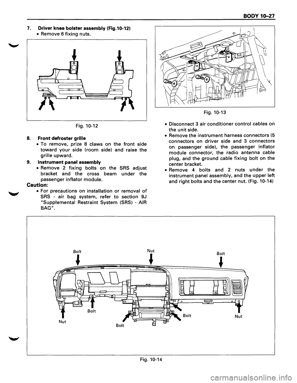
7. Driver knee bolster assembly (Fig.10-12)
• Remove 6 fixing nuts.
Fig.
10-12
8. Front defroster grille
•
To remove, prize 8 claws on the front side
toward your side (room side) and raise the
grille upward.
9. Instrument panel assembly
•
Remove 2 fixing bolts on the SRS adjust
bracket and the cross beam under the
passenger inflator module.
Caution:
• For precautions on installation or removal of
SRS -air bag system, refer to section 9J
"Supplemental Restraint System (SRS) -AIR
BAG".
Bolt
~
Nut Nut
~
Fig. 10-14
BODY 10-27
Fig. 10-13
•
Disconnect 3 air conditioner control cables on
the
unit side.
• Remove the instrument harness connectors (5
connectors on
driver side and 3 connectors
on passenger side), the passenger inflator
module connector, the radio antenna cable
plug,
and the ground cable fixing bolt on the
center bracket.
• Remove 4 bolts and 2 nuts under the
instrument panel assembly, and the upper left
and right bolts and the center nut. (Fig. 1 0-14)
Bolt
~
Bolt Nut
Page 1786 of 1928
10-28 BODY
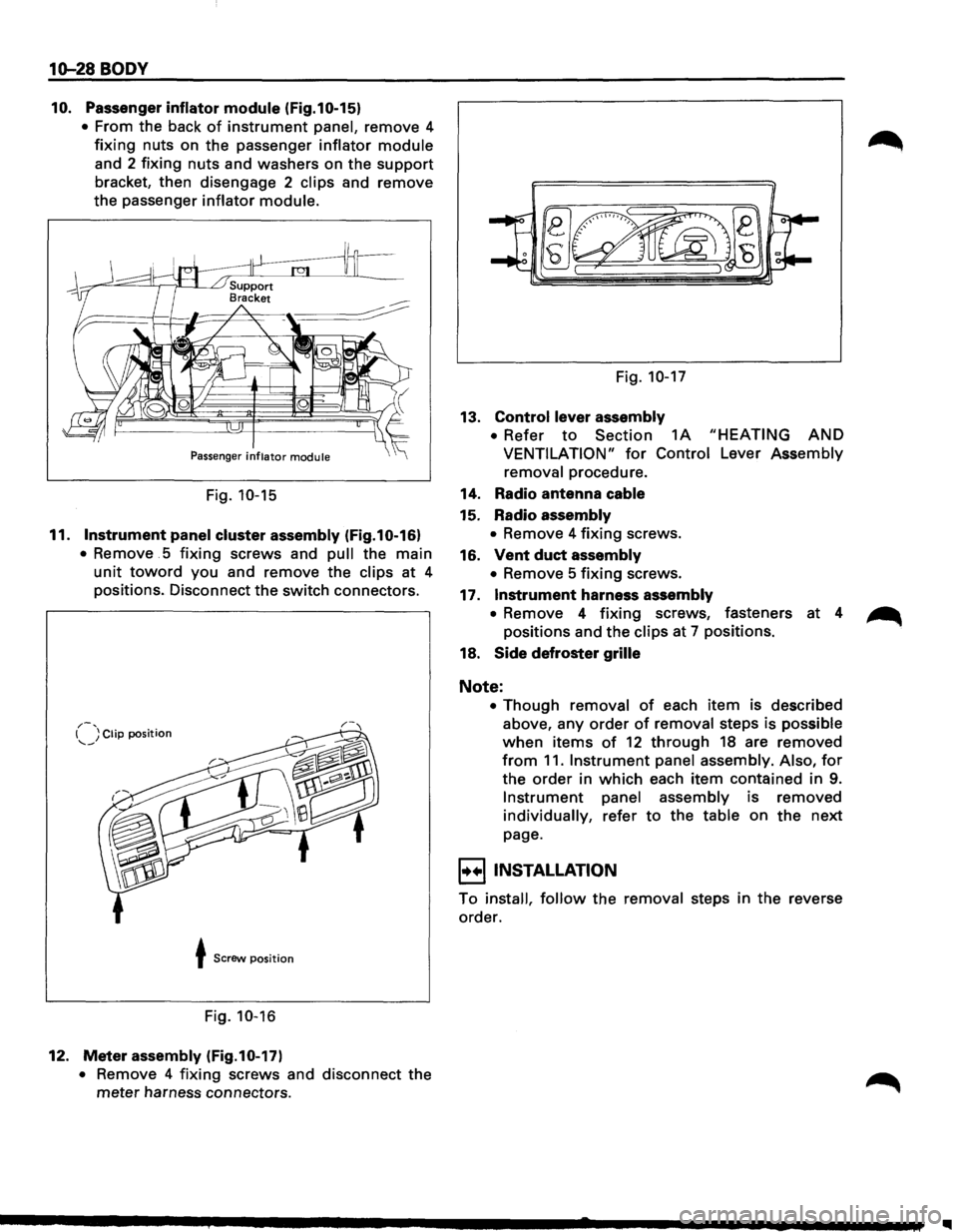
10. Passenger inflator module (Fig.10-15)
• From the back of instrument panel, remove 4
fixing nuts on the passenger inflator module
and 2 fixing nuts and washers on the support
bracket, then disengage 2 clips and remove
the passenger
inflator module.
Passenger inflator module
Fig. 10-15
11. Instrument panel cluster assembly (Fig.10-16)
• Remove . 5 fixing screws and pull the main
unit toward you and remove the clips at 4
positions. Disconnect the switch connectors.
,.-, I ) Clip position --~
t Screw position
Fig. 10-16
12. Meter assembly (Fig.10-17)
• Remove 4 fixing screws and disconnect the
meter harness connectors. Fig.
10-17
13. Control lever
assembly
• Refer to Section 1A "HEATING AND
VENTILATION" for Control Lever Assembly
removal procedure.
14. Radio antenna cable
15. Radio assembly
• Remove 4 fixing screws.
16.
Vent duct assembly
• Remove 5 fixing screws.
17.
Instrument harness assembly
• Remove 4 fixing screws, fasteners at 4 ~
positions and the clips at 7 positions.
18.
Side defroster grille
Note:
• Though removal of each item is described
above, any
order of removal steps is possible
when items of 12 through 18 are removed
from 11. Instrument panel assembly. Also, for
the order in which each item contained in 9.
Instrument panel assembly is removed
individually, refer to the table on the next
page.
I+•IINSTALLATION
To install, follow the removal steps in the reverse
order.
II
Page 1787 of 1928
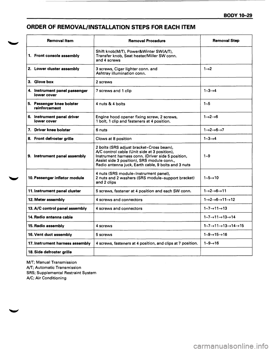
ORDER OF REMOVAL/INSTALLATION STEPS FOR EACH ITEM
Removal Item
1. Front console assembly
2. Lower cluster assembly
3. Glove box
4. Instrument panel passenger lower cover
5. Passenger knee bolster reinforcement
6. Instrument panel driver lower cover
7. Driver knee bolster
8. Front defroster grille
9. Instrument panel assembly
10. Passenger inflator module
11.1nstrument panel cluster
12. Meter assembly
13. A/C control panel assembly
14. Radio antenna cable
15. Radio assembly
16. Vent duct assembly
17 .Instrument harness assembly
18. Side defroster grille
MfT; Manual Transmission
A/T;
Automatic Transmission Removal
Procedure
Shift
knob(MfT), Power&Winter SW(A/T),
Transfer knob, Seat heater/Miller SW conn.
and 4 screws
3 screws, Ciger lighter conn. and
Ashtray illumination conn.
2 screws
7 screws and 1 clip
4 nuts & 4 bolts
Engine hood opener fixing screw, 2 screws, 1 bolt, 1 clip and fasteners at 4 position.
6 nuts
Claws at 8 position
2 bolts (SRS adjust bracket-Cross beam), A!C control cable (Unit side at 3 position), Instrument harness conn. (Driver side 5 position,
Assist side 3 position), SRS module conn.,
Radio antenna juck, Earth
cable, 9 bolts and 3 nuts
4 nuts (SRS module-Instrument panel), 2 nuts and 2 washers (SRS module-support bracket)
and 2 clips
5 screws, fastener at 4 position and each SW conn.
4 screws and connectors
4 screws and connectors
4 screws
5 screws
4 screws, fasteners at 4 position, and clips at 7 position.
SRS; Supplemental Restraint System
A!C; Air Conditioning
BODY 10-29
Removal Step
1~2
1~3~4
1~5
1~2~6
1~2~6~7
1-3~4
1~9
1-5~10
1~2~6~11
1~2~6~11~12
1-7~11~13
1-7~11~13~14
1~7~11~13~14~15
1-9~15~16
1-9~16
Page 1788 of 1928
10-30 BODY
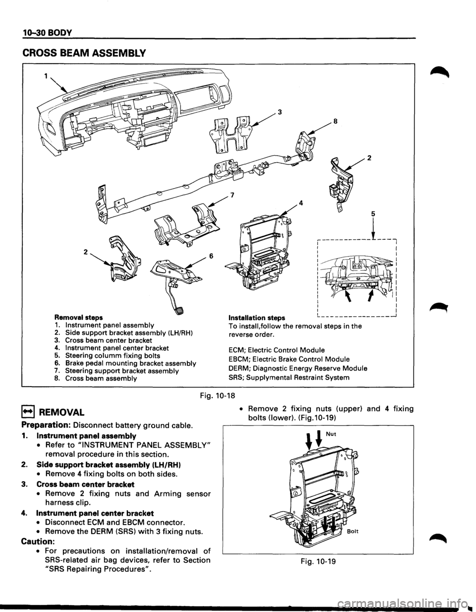
CROSS BEAM ASSEMBLY
2 6
Removal steps 1. Instrument panel assembly 2. Side support bracket assembly (LH/RH)
3. Cross beam center bracket 4. Instrument panel center bracket 5. Steering columm fixing bolts
6. Brake pedal mounting bracket assembly 7. Steering support bracket assembly 8. Cross beam assembly
3
4
Installation steps
8 2
5
, -----------L_l
I I
I
I I
~~~~~®~! II I I I I !._ ___ ---------___ _J
To install, follow the removal steps in the
reverse order.
ECM; Electric Control Module
EBCM; Electric Brake Control Module
DERM; Diagnostic Energy Reserve Module
SRS; Supplymental Restraint System
Fig. 10-18
E) REMOVAL
Preparation: Disconnect battery ground cable.
1. Instrument panel assembly
• Refer to "INSTRUMENT PANEL ASSEMBLY"
removal procedure in this section.
2.
Side support bracket assembly (LH/RH)
• Remove 4 fixing bolts on both sides.
3. Cross beam
center bracket
• Remove 2 fixing nuts and Arming sensor
harness clip.
4. Instrument panel center bracket
• Disconnect ECM and EBCM connector.
• Remove the DERM (SRS) with 3 fixing nuts.
Caution:
• For precautions on installation/removal of
SRS-related air bag devices, refer to Section
"SRS Repairing Procedures". •
Remove
2 fixing nuts (upper) and 4 fixing
bolts (lower). (Fig.10-19)
Fig. 10-19
Page 1789 of 1928
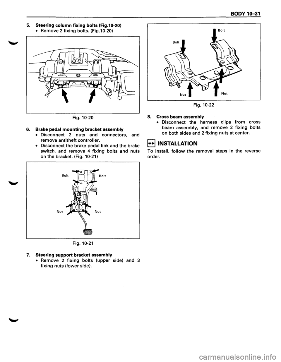
5. Steering column fixing bolts (Fig.10-20)
•
Remove 2 fixing bolts. (Fig.10-20)
Fig. 10-20
6. Brake pedal mounting bracket assembly
•
Disconnect 2 nuts and connectors, and
remove antitheft
controller.
•
Disconnect the brake pedal link and the brake
switch, and remove 4
fixing bolts and nuts
on the bracket. (Fig.
10-21)
Nut
Fig. 10-21
7. Steering support bracket assembly
•
Remove 2 fixing bolts (upper side) and 3
fixing nuts (lower side).
BODY 10-31
Bolt
Fig. 10-22
8. Cross beam assembly
•
Disconnect the harness clips from cross
beam
assembly, and remove 2 fixing bolts
on both sides and 2 fixing nuts at center.
EJ INSTALLATION
To install, follow the removal steps in the reverse
order.
Page 1790 of 1928
10-32 BODY
DOORS
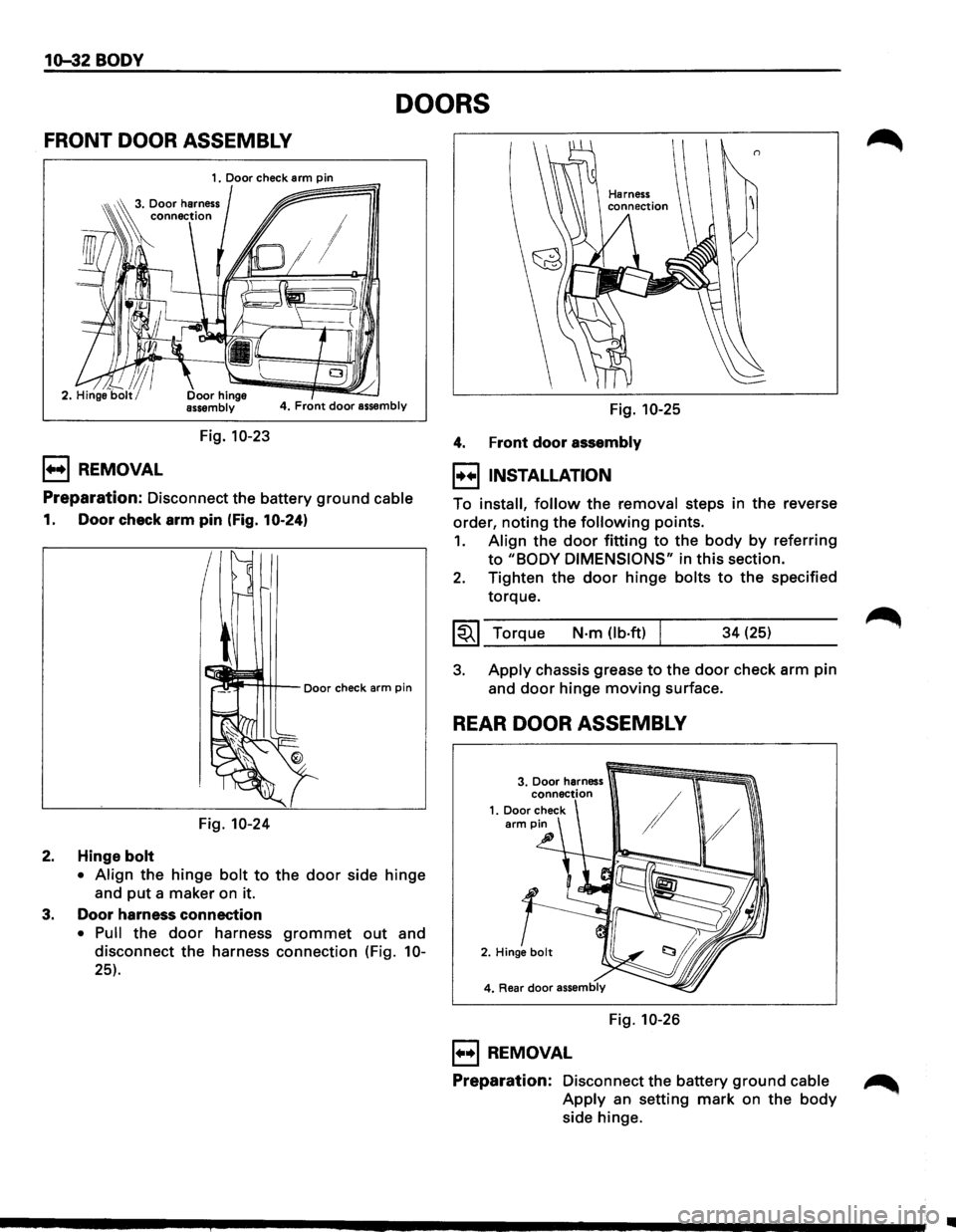
FRONT DOOR ASSEMBLY
4. Front door assembly
Fig. 10-23
1++1 REMOVAL
Preparation: Disconnect the battery ground cable
1. Door check arm pin (Fig. 10-24)
Fig.
10-24
2. Hinge bolt
• Align the hinge bolt to the door side hinge
and
put a maker on it.
3. Door harness connection
• Pull the door harness grommet out and
disconnect the harness connection (Fig.
10-
25). Fig.
10-25
4. Front
door assembly
I++IINSTALLATION
To install, follow the removal steps in the reverse
order,
noting the following points.
1. Align the door fitting to the body by referring
to "BODY DIMENSIONS" in this section.
2. Tighten the door hinge bolts to the specified
torque.
~~~ Torque N·m (lb·ftl I 34 (25)
3. Apply chassis grease to the door check arm pin
and
door hinge moving surface.
REAR DOOR ASSEMBLY
Fig. 10-26
1++1 REMOVAL
Preparation: Disconnect the battery ground cable ~
Apply an setting mark on the body
side hinge.
•