ISUZU TROOPER 1995 Workshop Manual
Manufacturer: ISUZU, Model Year: 1995, Model line: TROOPER, Model: ISUZU TROOPER 1995Pages: 1928
Page 1791 of 1928
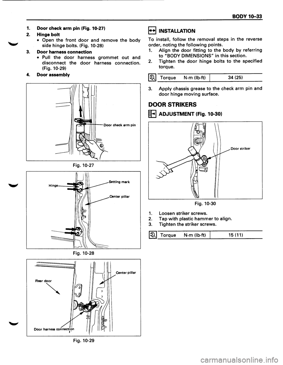
1. Door check arm pin (Fig. 10-27)
2. Hinge bolt
• Open the front door and remove the body
side hinge bolts. (Fig. 10-28)
3. Door harness connection
• Pull the door harness grommet out and
disconnect
the door harness connection.
(Fig. 1
0-29)
4. Door assembly
Door check arm pin
Fig. 10-27
Setting mark
Center pillar
Fig. 10-28
LJ
Center pillar
Rear door
~
Fig. 10-29
BODY 1o:-33
I++IINSTALLATION
To install, follow the removal steps in the reverse
order,
noting the following points.
1. Align the door fitting to the body by referring
to "BODY DIMENSIONS" in this section.
2. Tighten the door hinge bolts to the specified
torque.
1~1 Torque N·m (lb.ft) 34 (25)
3. Apply chassis grease to the check arm pin and
door hinge moving surface.
DOOR STRIKERS
I~EI ADJUSTMENT (fig. 10-30)
Door striker
Fig. 10-30
1. Loosen striker screws.
2. Tap with plastic hammer to align.
3. Tighten the striker screws.
~~~ Torque N·m {lb·ft) 15 (11)
Page 1792 of 1928
1o-34 BODY
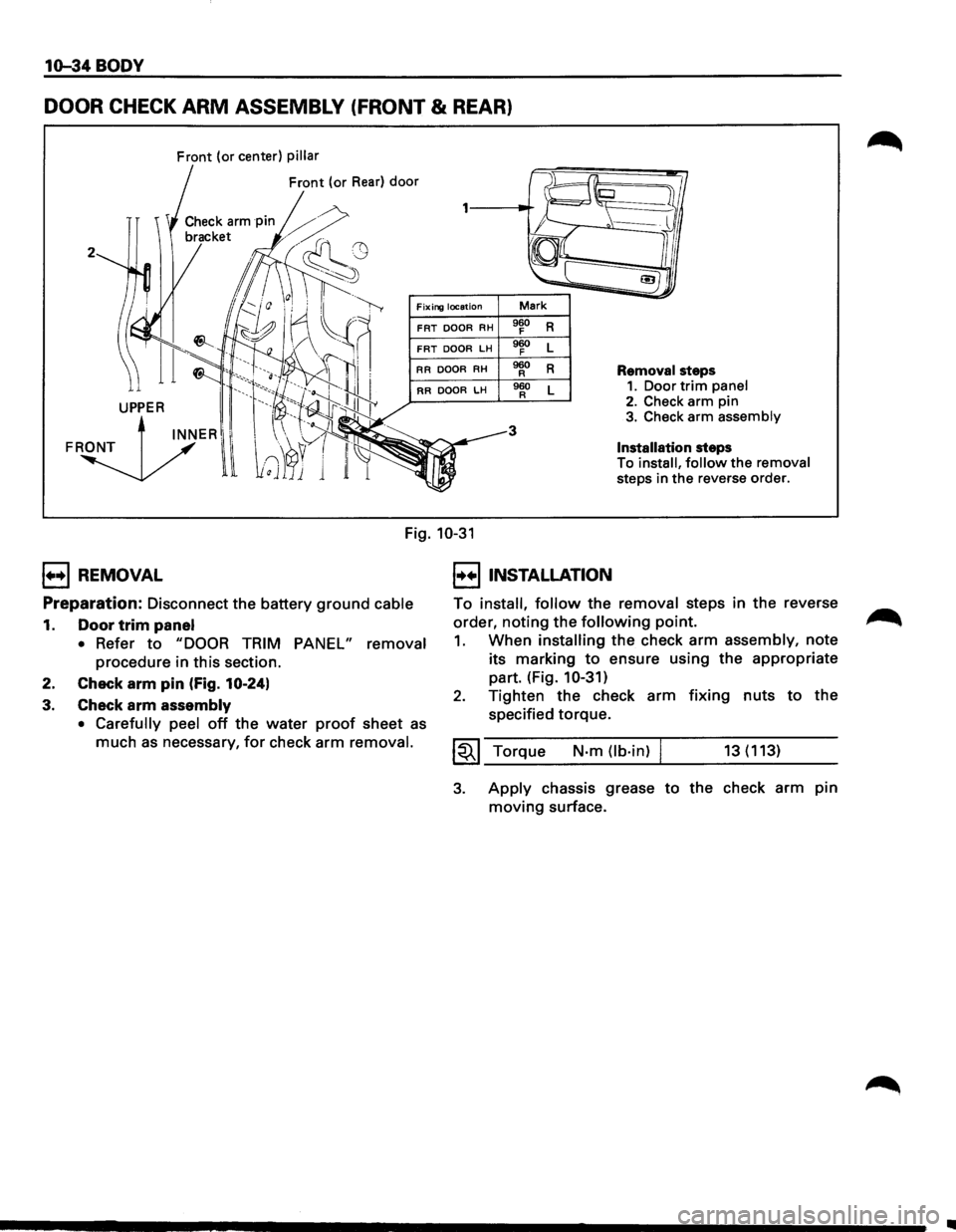
DOOR CHECK ARM ASSEMBLY (FRONT & REAR)
Front (or center) pillar
Front (or Rear) door
2
Fixing location Mark
FRT DOOR RH 960 R F
FRT DOOR LH 960 L F
RR
DOOR RH 960 R R Removal steps
RR DOOR LH 960 L R 1. Door trim panel
3
2. Check arm pin 3. Check arm assembly
Installation steps
To
install, follow the removal
steps in
the reverse order.
Fig. 10-31
1++1 REMOVAL
Preparation:
Disconnect the battery ground cable
1. Door trim panel
• Refer to "DOOR TRIM PANEL" removal
procedure in this section.
2. Check
arm pin (Fig. 10-24)
3. Check arm assembly
• Carefully peel off the water proof sheet as
much as necessary, for check arm removal.
I••IINSTALLATION
To install, follow the removal steps in the reverse
order,
noting the following point.
1. When installing the check arm assembly, note
its marking
to ensure using the appropriate
part. (Fig.
10-31)
2. Tighten the check arm fixing nuts to the
specified torque.
~~~ Torque N-m (lb·in) I 13(113)
3. Apply chassis grease to the check arm pin
moving surface.
..
Page 1793 of 1928
BODY 1Q-35
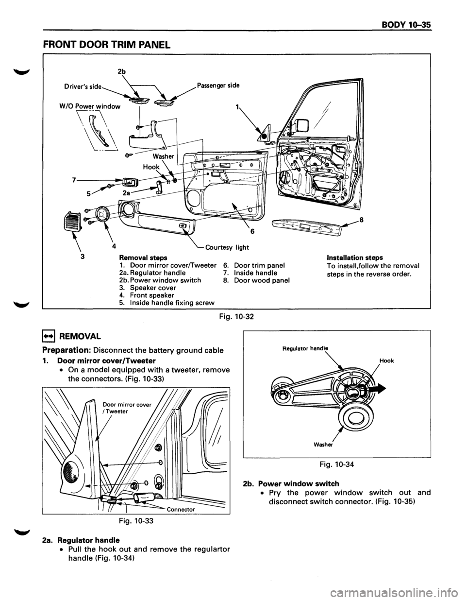
FRONT DOOR TRIM PANEL
2b
Driver's
side Passenger side
7
4
3 Removal steps Installation steps 1. Door mirror cover/Tweeter 2a. Regulator handle 6. Door trim panel To install, follow the removal
steps in the reverse order. 7. Inside handle 2b. Power window switch 8. Door wood panel 3. Speaker cover 4. Front speaker 5. Inside handle fixing screw
Fig. 10-32
l++l REMOVAL
Preparation: Disconnect the battery ground cable
1. Door mirror cover/Tweeter
• On a model equipped with a tweeter, remove
the connectors. (Fig.
10-33)
Door mirror cover /Tweeter
Fig. 10-33
2a. Regulator handle
• Pull the hook out and remove the regulartor
handle (Fig. 10-34)
Regulator handle
Washer
Fig. 10-34
2b. Power window switch
• Pry the power window switch out and
disconnect
switch connector. (Fig. 10-35)
Page 1794 of 1928
10-36 BODY
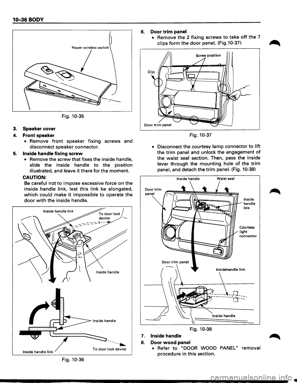
Power window switch
I
Fig. 10-35
3. Speaker cover
4. Front speaker
• Remove front speaker fixing screws and
disconnect speaker connector.
5.
Inside handle fixing screw
• Remove the screw that fixes the inside handle,
slide
the inside handle to the position
illustrated, and leave it there for the moment.
CAUTION:
Be careful not to impose excessive force on the
inside
handle link, lest this link be elongated,
which could make it impossible to operate the
door with the inside handle.
Inside handle
--.......
Inside handle link To door lock
device
Fig. 10-36
6. Door trim panel
• Remove the 2 fixing screws to take off the 7
clips form the door panel. (Fig.1 0-37)
Fig. 10-37
•
Disconnect the courtesy lamp connector to lift
the trim panel and unlock the engagement of
the waist seal section. Then, pass the inside
lever through the mounting hole of the trim
panel, and detach the trim panel. (Fig. 10-38)
Inside handle
Door
trim panel
Door
trim panel
7. Inside handle
Fig. 10-38
8. Door wood panel
Waist seal
Inside handle
link
connector
• Refer to "DOOR WOOD PANEL" removal
procedure in this section.
Ill
Page 1795 of 1928
I••! INSTALLATION
To install, follow the removal steps in the reverse
order,
noting the following point.
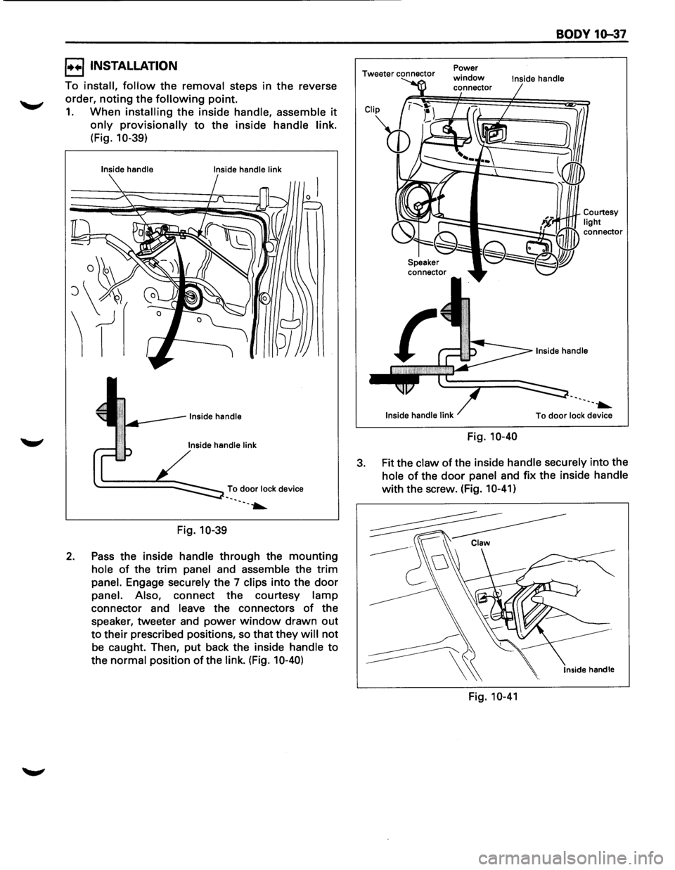
1. When installing the inside handle, assemble it
only provisionally to the inside handle link.
(Fig. 10-39)
Inside handle
Inside handle link
To door lock device ·-. ·--~
Fig. 10-39
2. Pass the inside handle through the mounting
hole of the trim panel and assemble the trim
panel. Engage securely the 7 clips into the door
panel. Also, connect the courtesy lamp
connector and leave the connectors of the
speaker, tweeter and power
window drawn out
to their prescribed positions, so that they will not
be caught. Then, put back the inside handle to
the
normal position of the link. (Fig. 10-40)
Tweeter connector
Speaker connector Power
window connector
Inside
handle link
Fig. 10-40
BODY 10-37
Inside handle
·-. --~
To door lock device
3. Fit the claw of the inside handle securely into the
hole of the door panel and fix the inside handle
with the screw. (Fig. 10-41)
Inside handle
Fig. 10-41
Page 1796 of 1928
1o-38 BODY
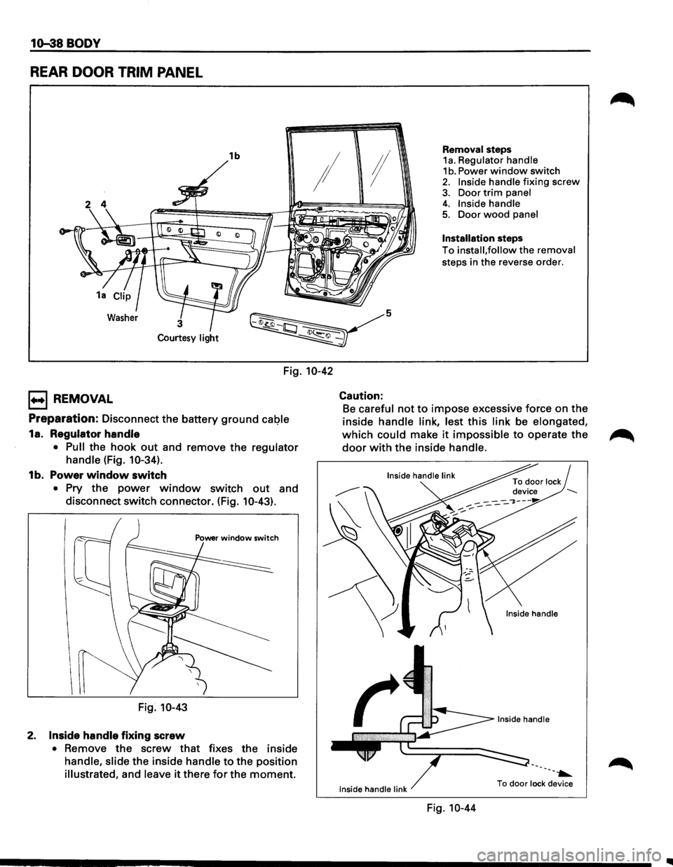
REAR DOOR TRIM PANEL
1b
~
Removal steps 1a. Regulator handle 1 b. Power window switch 2. Inside handle fixing screw
3. Door trim panel
!I
I ;I
Courtesy light
Fig. 10-42
1+•1 REMOVAL
Preparation: Disconnect the battery ground caQie
1a. Regulator handle
• Pull the hook out and remove the regulator
handle
(Fig. 10-34).
1b. Power window switch
• Pry the power window switch out and
disconnect switch connector. (Fig.
10-43).
Fig. 10-43
2. Inside handle fixing screw
• Remove the screw that fixes the inside
handle, slide the inside handle to the position
illustrated, and leave it there for the moment.
5
Caution:
4. Inside handle 5. Door wood panel
Installation steps
To install, follow the removal
steps in the reverse order.
Be careful not to impose excessive force on the
inside
handle link, lest this link be elongated,
which could make it impossible to operate the
door with the inside handle.
Inside handle link
Fig. 10-44
---~
To door lock device
Page 1797 of 1928
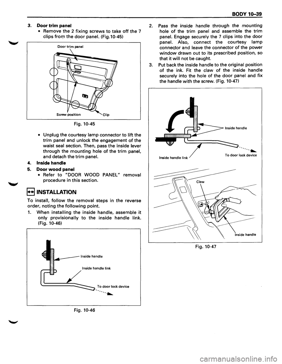
3. Door trim panel
• Remove the 2 fixing screws to take off the 7
clips fro111 the door panel. (Fig.10-45)
Door trim panel
Screw position
Fig. 10-45
• Unplug
the courtesy lamp connector to lift the
trim panel and unlock the engagement of the
waist
seal section. Then, pass the inside lever
through the mounting hole of the trim panel,
and detach the trim panel.
4. Inside handle
5. Door wood panel
• Refer to "DOOR WOOD PANEL" removal
procedure in this section.
B INSTALLATION
To install, follow the removal steps in the reverse
order,
noting the following point.
1. When installing the inside handle, assemble it
only provisionally to the inside handle link.
(Fig. 10-46)
Inside handle link
To door lock device
--.....
Fig. 10-46
BODY 10-39
2. Pass the inside handle through the mounting
hole of the trim panel and assemble the trim
panel. Engage securely the 7 clips into the door
panel. Also, connect the courtesy lamp
connec:tor and leave the connector of the power
window drawn out to its prescribed position, so
that
it will not be caught.
3. Put back the inside
handle to the original position
of the ink. Fit the claw of the inside handle
securely
into the hole of the door panel and fix
the handle with the screw. (Fig. 10-47)
---.....
Inside handle link To door lock
device
Fig. 10-47
Page 1798 of 1928
10-40 BODY
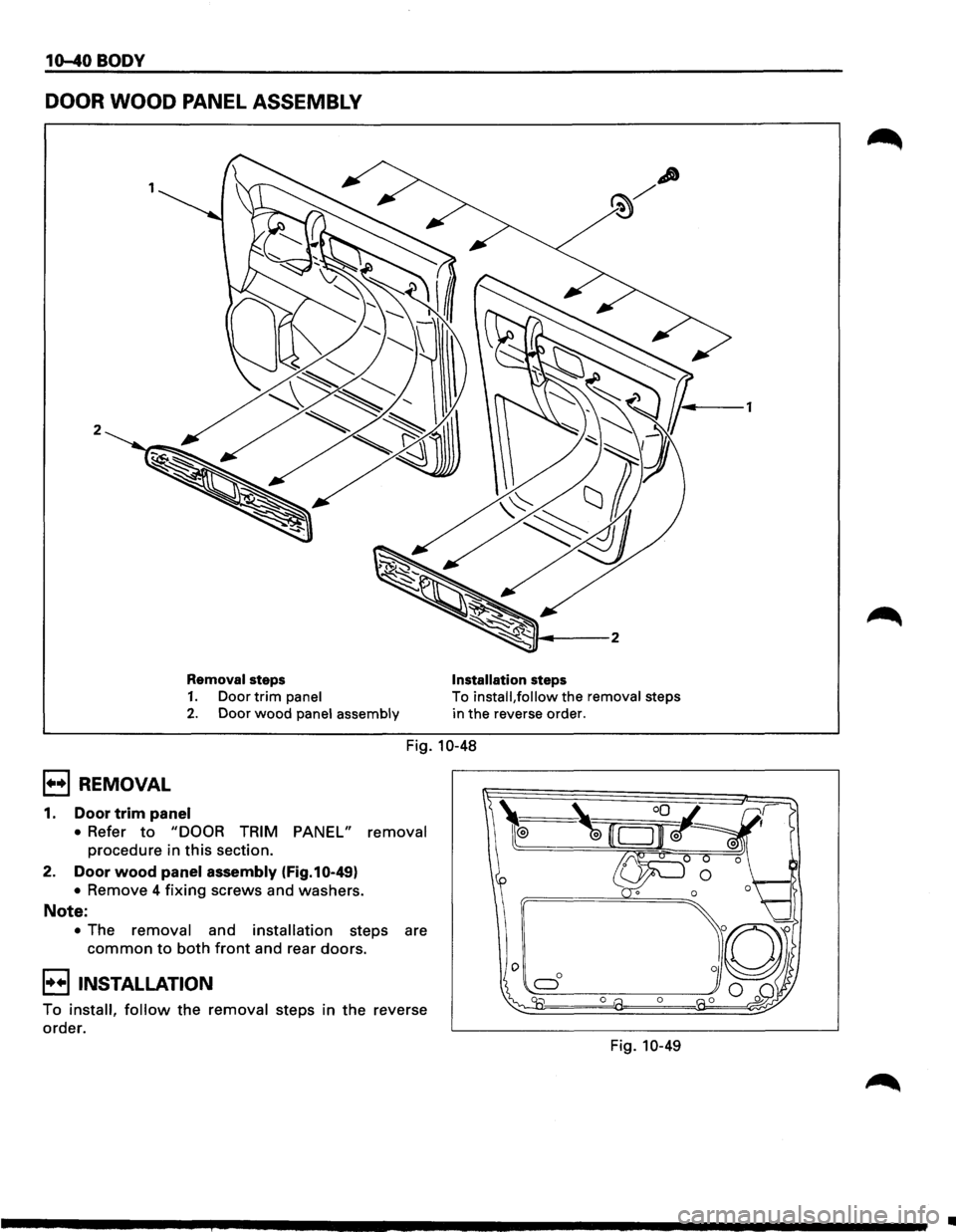
DOOR WOOD PANEL ASSEMBLY
2
Removal steps
1. Door trim panel
2. Door wood panel assembly Installation
steps
To
install, follow the removal steps
in the reverse order.
Fig. 10-48
B REMOVAL
1. Door trim panel
• Refer to "DOOR TRIM PANEL" removal
procedure in this section.
2. Door wood panel assembly (Fig.10-49)
• Remove 4 fixing screws and washers.
Note:
• The removal and installation steps are
common to both front and rear doors.
8 INSTALLATION
To install, follow the removal steps in the reverse
order. Fig.
10-49
•
Page 1799 of 1928
BODY 10-41
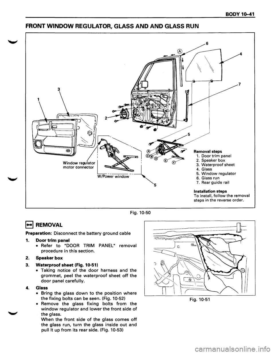
FRONT WINDOW REGULATOR, GLASS AND AND GLASS RUN
3
Window regulator I ~ :
motor connector L__ --~
W/Power window '
Fig. 10-50
B REMOVAL
Preparation: Disconnect the battery ground cable
1. Door trim panel
•
Refer to "DOOR TRIM PANEL" removal
procedure in this section.
2. Speaker
box
3. Waterproof sheet (Fig. 10-51)
•
Taking notice of the door harness and the
grommet, peel the waterproof sheet off the
door panel carefully.
4. Glass
•
Bring the glass down to the position where
the fixing bolts can be seen. (Fig. 10-52)
•
Remove the glass fixing bolts from the
window regulator and lower the front side of
the glass.
When the front side of the glass comes off
the glass run, turn the glass inside out and
pull it up from its rear side. (Fig. 10-53)
5
Removal steps 1. Door trim panel 2. Speaker box 3. Waterproof sheet
4. Glass 5. Window regulator
6. Glass run 7. Rear guide rail
Installation steps To install, follow the removal steps in the reverse order.
Fig. 10-51
Page 1800 of 1928
10-42 BODY
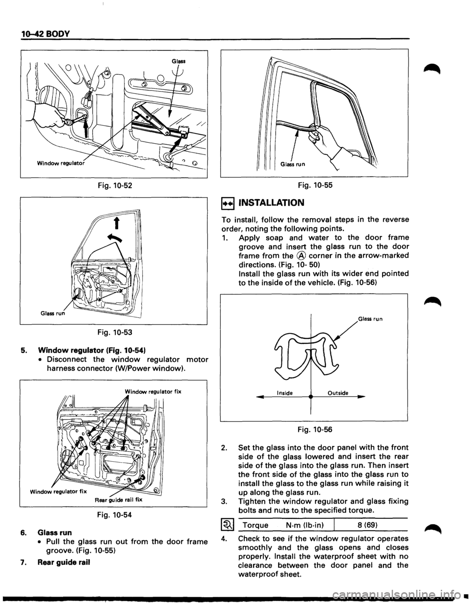
Fig. 10-52
Fig. 10-53
5. Window regulator (Fig. 10-54)
6.
7.
• Disconnect the window regulator motor
harness connector (W/Power window).
Window regulator fix
Rear guide rail fix
Fig. 10-54
Glass
run
• Pull the glass run out from the door frame
groove. (Fig. 10-55)
Rear
guide rail
Fig. 10-55
E) INSTALLATION
To install, follow the removal steps in the reverse
order,
noting the following points.
1. Apply soap and water to the door frame
groove and insert the glass run to the door
frame from the @ corner in the arrow-marked
directions. (Fig.
10-50)
2.
3.
Install the glass run with its wider end pointed
to the inside of the vehicle. (Fig. 10-56)
Glass run
Inside Outside
Fig. 10-56
Set the glass
into the door panel with the front
side of the glass lowered and insert the rear
side
of the glass into the glass run. Then insert
the
front side of the glass into the glass run to
install the glass to the glass run while raising it
up along the glass run.
Tighten the
window regulator and glass fixing
bolts and nuts to the specified torque.
~~~ _T_o_r~q_u_e ____ N_·m __ (l_b_·i_n) __ ~ ___ 8_(_6_9_) ____ _
4. Check to see if the window regulator operates
smoothly and the glass opens and closes
properly.
Install the waterproof sheet with no
clearance between the door panel and the
waterproof sheet.
•