engine oil ISUZU TROOPER 1995 Workshop Manual
[x] Cancel search | Manufacturer: ISUZU, Model Year: 1995, Model line: TROOPER, Model: ISUZU TROOPER 1995Pages: 1928
Page 1037 of 1928
2. Exhaust and transfer protectors
~~~ Torque N-m(lb.ft) 37 (27)
1. Skid plate
• Connect negative (-) battery cable.
• Install
engine hood.
• Adjust shift lock cable.
Refer to "Selector lever" in this section.
SOLENOID VALVE
(MAIN CASE VALVE BODY)
l••l REMOVAL
Preparation:
• Disconnect negative {-) battery cable.
•
Remove exhaust protector and exhaust pipe.
1. Main case oil pan
• Remove sixteen 10 mm screws, main case
oil pan, magnet, and gasket.
• Drain fluid.
Refer to "CHANGING TRANSMISSION
FLUID".
2. Oil filter
• Remove three 13 mm screws, oil filter.
3. Wiring harness
• Disconnect wiring harness from band control
solenoid,
shift solenoids and main case 4 pin
connector.
Pull only on connectors, not on
wiring harness.
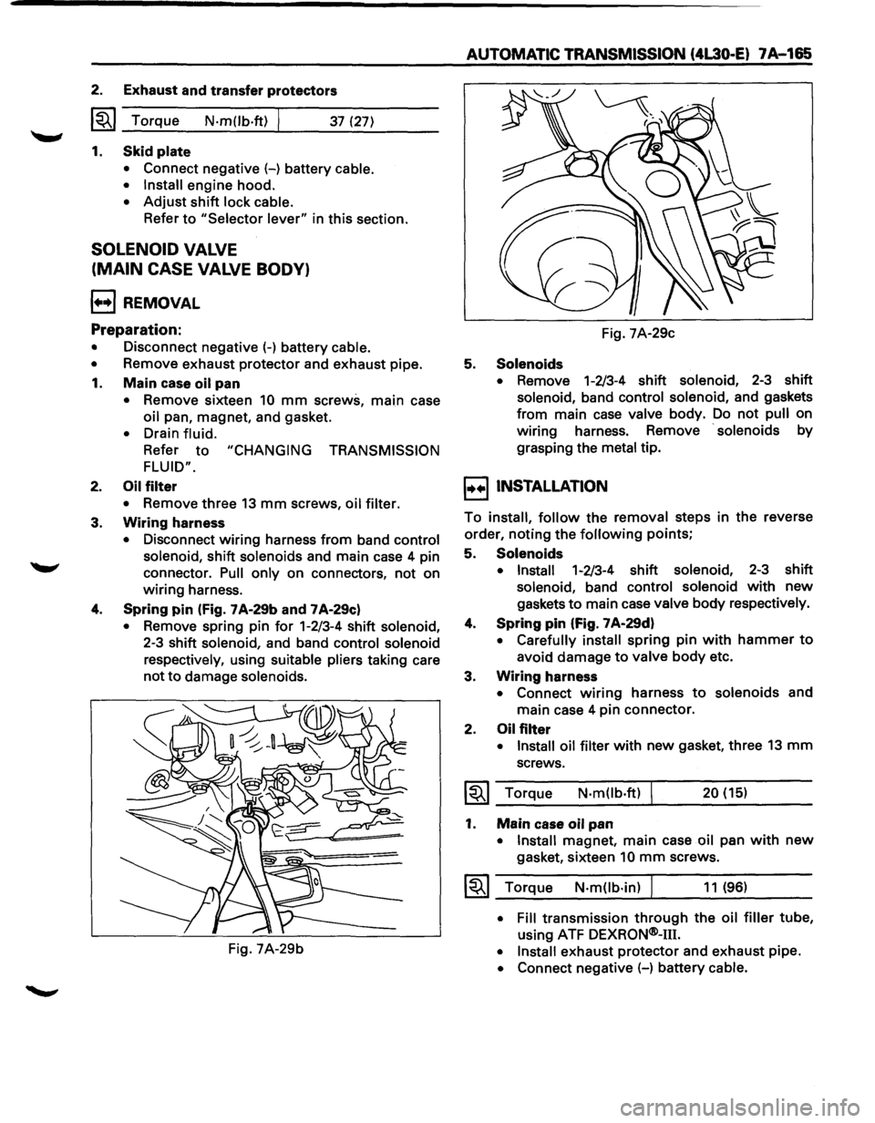
4. Spring pin (Fig. 7 A-29b and 7 A-29c)
• Remove spring pin for 1-2/3-4 shift solenoid,
2-3 shift solenoid, and band control solenoid
respectively,
using suitable pliers taking care
not to damage solenoids.
Fig. 7A-29b
AUTOMATIC TRANSMISSION (4L30 .. E) 7A-165
Fig. 7A-29c
5. Solenoids
• Remove 1-2/3-4 shift solenoid, 2-3 shift
solenoid, band control solenoid, and gaskets
from main case valve body. Do not pull on
wiring harness. Remove
· solenoids by
grasping the
metal tip.
I••! INSTALLATION
To install, follow the removal steps in the reverse
order,
noting the following points;
5. Solenoids
• Install 1-2/3-4 shift solenoid, 2-3 shift
solenoid, band control solenoid with new
gaskets to main case valve body respectively.
4. Spring pin (Fig. 7 A·29d)
• Carefully install spring pin with hammer to
avoid damage to valve body etc.
3. Wiring harness
• Connect wiring harness to solenoids and
main case 4 pin connector.
2. Oil filter
• Install oil filter with new gasket, three 13 mm
screws.
~~~ Torque N·m(lb.ft) 20 (15)
1. Main case oil pan
•
Install magnet, main case oil pan with new
gasket, sixteen 10 mm screws.
1~1 Torque N·m(lb·in) J 11 (96)
• Fill transmission through the oil filler tube,
using ATF DEXRQN®-m.
• Install exhaust protector and exhaust pipe.
• Connect negative (-) battery cable.
Page 1042 of 1928
7 A-170 AUTOMATIC TRANSMISSION (4L30-E)
TRANSMISSION OIL TEMPERATURE
SENSOR (ADAPTER CASE)
1•+1 REMOVAL
Preparation:
• Disconnect negative (-) battery cable.
•
Remove exhaust protector and exhaust pipe.
• Drain fluid.
•
Refer to "CHANGING TRANSMISSION FLUID".
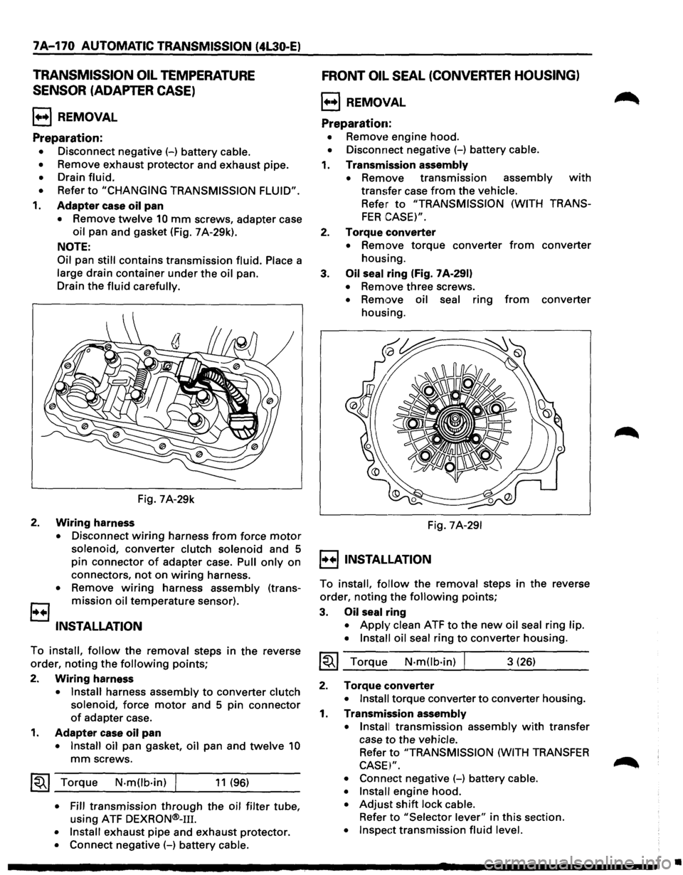
1. Adapter case oil pan
• Remove twelve 10 mm screws, adapter case
oil pan and gasket (Fig. 7 A-29k).
NOTE:
Oil
pan still contains transmission fluid. Place a
large drain container under the oil pan.
Drain the
fluid carefully.
Fig. 7A-29k
2. Wiring harness
• Disconnect wiring harness from force motor
solenoid, converter clutch solenoid and 5
pin connector
of adapter case. Pull only on
connectors,
not on wiring harness.
• Remove wiring harness assembly (trans
B mission oil temperature sensor).
INSTALLATION
To install, follow the removal steps in the reverse
order, noting the
following points;
2.
Wiring harness
• Install harness assembly to converter clutch
solenoid,
force motor and 5 pin connector
of adapter case.
1. Adapter case oil pan
• Install oil pan gasket, oil pan and twelve 10
mm screws.
~~~ Torque N·mOb·in) I 11 (96)
• Fill transmission through the oil filter tube,
using ATF
DEXRON®-111.
• Install exhaust pipe and exhaust protector.
• Connect negative (-) battery cable.
FRONT OIL SEAL (CONVERTER HOUSING)
l++l REMOVAL
Preparation:
• Removt~ engine hood.
• Disconnect negative (-) battery cable.
1. Transmission assembly
•
Remove transmission assembly with
transfer case from the vehicle.
Refer to "TRANSMISSION (WITH TRANS
FER CASE)".
2. Torque converter
• Remove torque converter from converter
housing.
3.
Oil seal ring (Fig. 7 A-291)
• Remove three screws.
• Remove oil seal ring from converter
housing.
Fig.
7A-291
I++IINSTALLATION
To install, follow the removal steps in the reverse
order, noting the
following points;
3. Oil seal ring
• Apply clean ATF to the new oil seal ring lip.
• Install oil seal
ring to converter housing.
~~~ Torque N·mOb·in) I 3 (26)
2. Torque converter
• Install torque converter to converter housing.
1. Transmission assembly
• Install
transmission assembly with transfer
case
to the vehicle.
Refer to "TRANSMISSION (WITH TRANSFER
CASE I".
• Connoct negative (-) battery cable.
• Install
engine hood.
• Adjust shift lock cable.
Refer to "Selector lever" in this section.
• Inspect transmission fluid level.
•
Page 1060 of 1928
7A-188 AUTOMATIC TRANSMISSION (4L30-E)
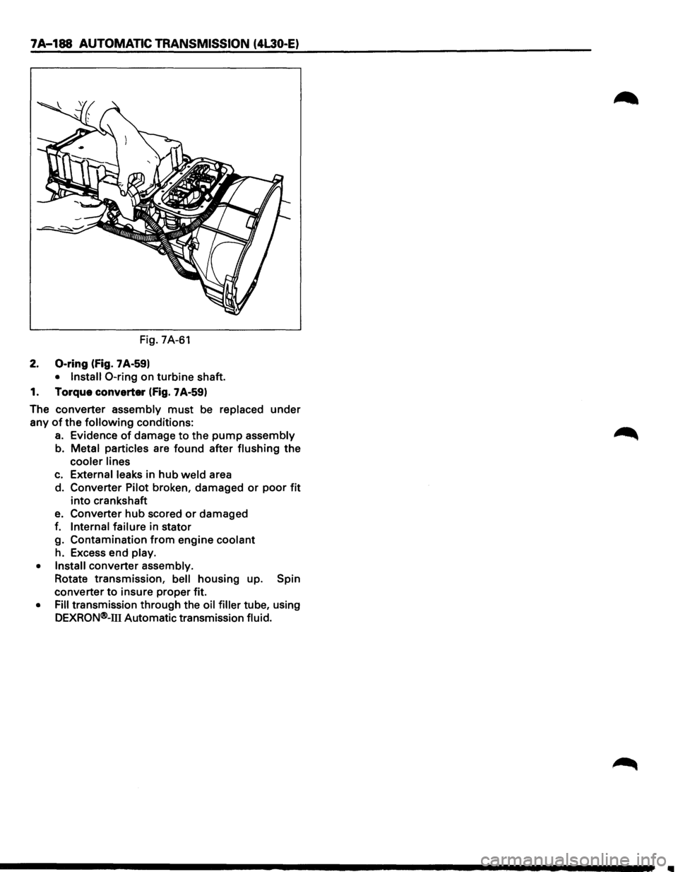
Fig. 7A-61
2. 0-ring (fig. 7 A-59)
• Install 0-ring on turbine shaft.
1. Torque converter
(fig. 7A-59)
The converter assembly
must be replaced under
any
of the following conditions:
a. Evidence of damage to the pump assembly
b. Metal particles are found after flushing
the
cooler lines
c. External leaks in hub weld area
d. Converter Pilot broken, damaged
or poor fit
into crankshaft
e. Converter hub scored or damaged
f.
Internal failure in stator
g. Contamination
from engine coolant
h. Excess end play.
• Install converter assembly.
Rotate transmission,
bell housing up. Spin
converter
to insure proper fit.
• Fill transmission through the oil filler tube, using
DEXRQN®-111 Automatic transmission fluid.
Page 1079 of 1928
AUTOMATIC TRANSMISSION (4L30-E) 7 A-207
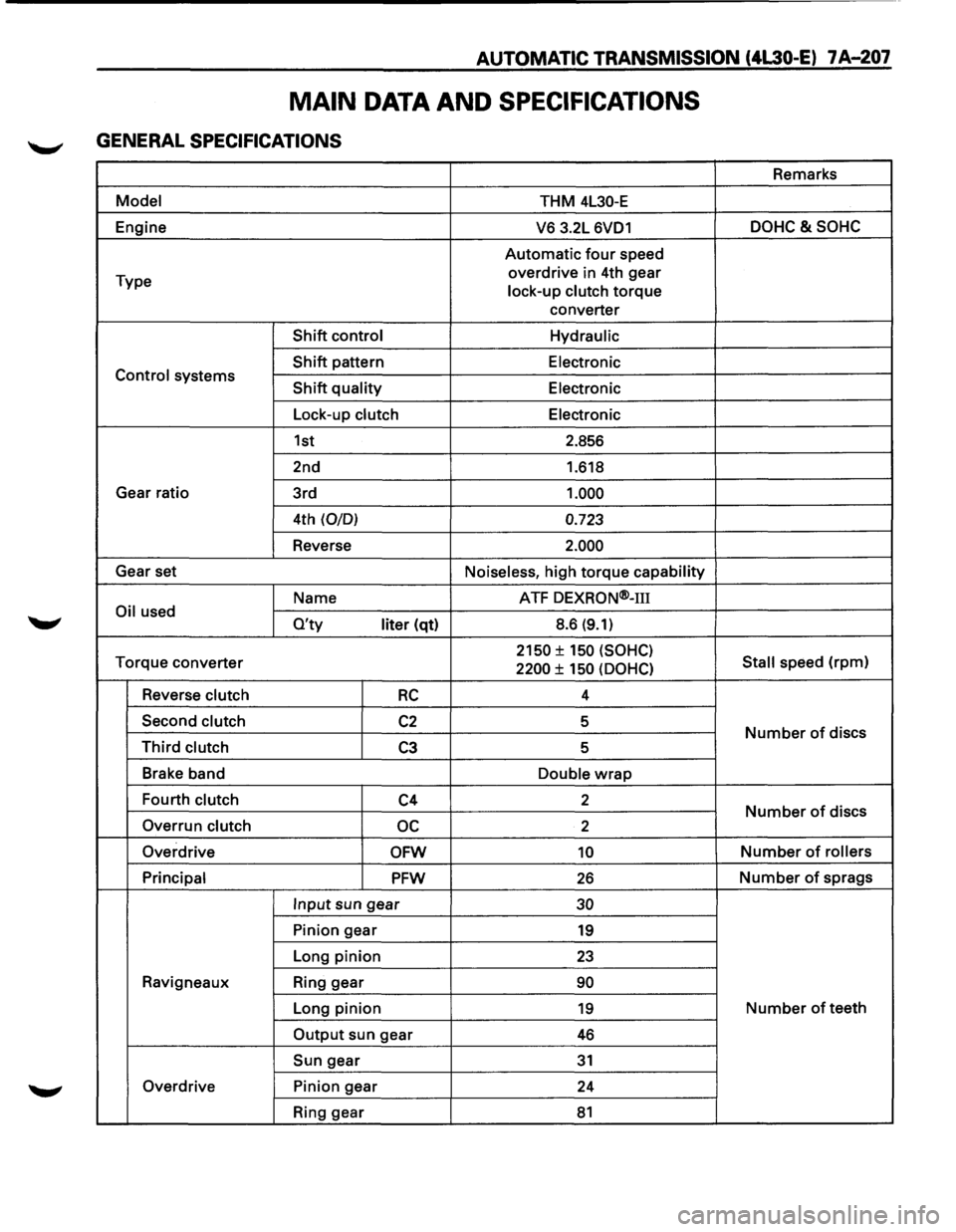
MAIN DATA AND SPECIFICATIONS
GENERAL SPECIFICATIONS
Remarks
Model THM 4L30-E
Engine
V6 3.2L 6VD1 DOHC&SOHC
Automatic four speed
Type overdrive
in 4th gear
lock-up clutch
torque
converter
Shift control Hydraulic
Shift pattern
Electronic Control systems Shift quality Electronic
Lock-up clutch Electronic
1st 2.856
2nd 1.618
Gear ratio
3rd
1.000
4th (0/0) 0.723
Reverse 2.000
Gear set
Noiseless, high torque capability
Name ATF
DEXRON®-m
Oil used O'ty liter (qt) 8.6 (9.1)
Torque
converter 2150 ± 150 (SOHC)
Stall speed (rpm) 2200 ± 150 (OOHC)
Reverse clutch RC 4
Second clutch
C2 5 Number of discs Third clutch C3 5
Brake band
Double
wrap
Fourth clutch C4 2 Number of discs
Overrun clutch oc 2
Overdrive
OFW 10 Number of rollers
Principal
PFW 26 Number of sprags
Input sun gear 30
Pinion gear 19
Long pinion 23
Ravigneaux Ring gear 90
Long pinion 19 Number of teeth
Output sun gear 46
Sun gear 31
Overdrive Pinion gear
24
Ring gear
81
Page 1106 of 1928
78-16 MANUAL TRANSMISSION
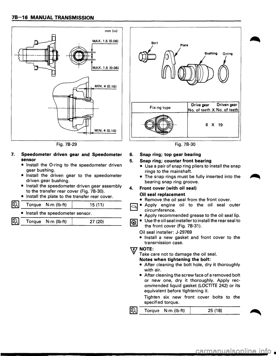
7.
mm{in)
MAX. 1.5 (0.06)
MAX. 1.5 10.06)
MIN. 4 (0.16)
MIN. 4 (0.16)
Fig. 78-29
Speedometer driven gear and Speedometer
sensor
• Install the 0-ring to the speedometer driven
gear bushing.
• Install the driven gear to the speedometer
driven gear bushing.
• Install the speedometer driven gear assembly
to the transfer rear cover (Fig. 78-30).
• Install the plate to the transfer rear cover.
l"i't I Torque N·m (lb·ft) ~ _...:.____---~... ___ _ 15 (11)
• Install the speedometer sensor.
I~I_T_o_rq...;_u_e_N_·_m_(_lb_·ft_l----~. ___ 2_7_(2_0_) __ _
Plate Bolt
~
Fix1ing type Drive gear Driven gear
No. of teeth
X No. of teeth
6 X 19
Fig. 78-30
6. Snap ring; top gear bearing
5. Snap ring; counter front bearing
• Use a pair of snap ring pliers to install the snap
rings to the mainshaft.
• The snap rings must be fully inserted into the
bearing snap ring groove.
4. Front cover (with oil seal)
Oil seal
replacement
• Remove the oil seal from the front cover.
c:::;J • Apply engine oil to the oil seal outer
D circumference.
• Apply recommended grease to the oil seal lip.
1®.1• Use the oil seal installer to install the rear seal to
the
front cover (Fig. 78-31 ).
Oil seal installer: J-29769
• Install a new gasket and front cover to the
transmission case.
'\f7 NOTE:
"+({ Take care not to damage the oil seal.
Notes when tightening the bolt:
• After Gleaning the bolt hole, dry it thoroughly
with air.
• After Gleaning the screw face of a removed bolt
or new one, dry it thoroughly. Apply rec
omme~nded liquid gasket (LOCTITE 242) or its
equivalent before tightening it.
Tighten six
new front cover bolts to the
specified torque.
1~1 Torque N·m (lb·ft) 25 (18)
..
Page 1116 of 1928
78-26 MANUAL TRANSMISSION
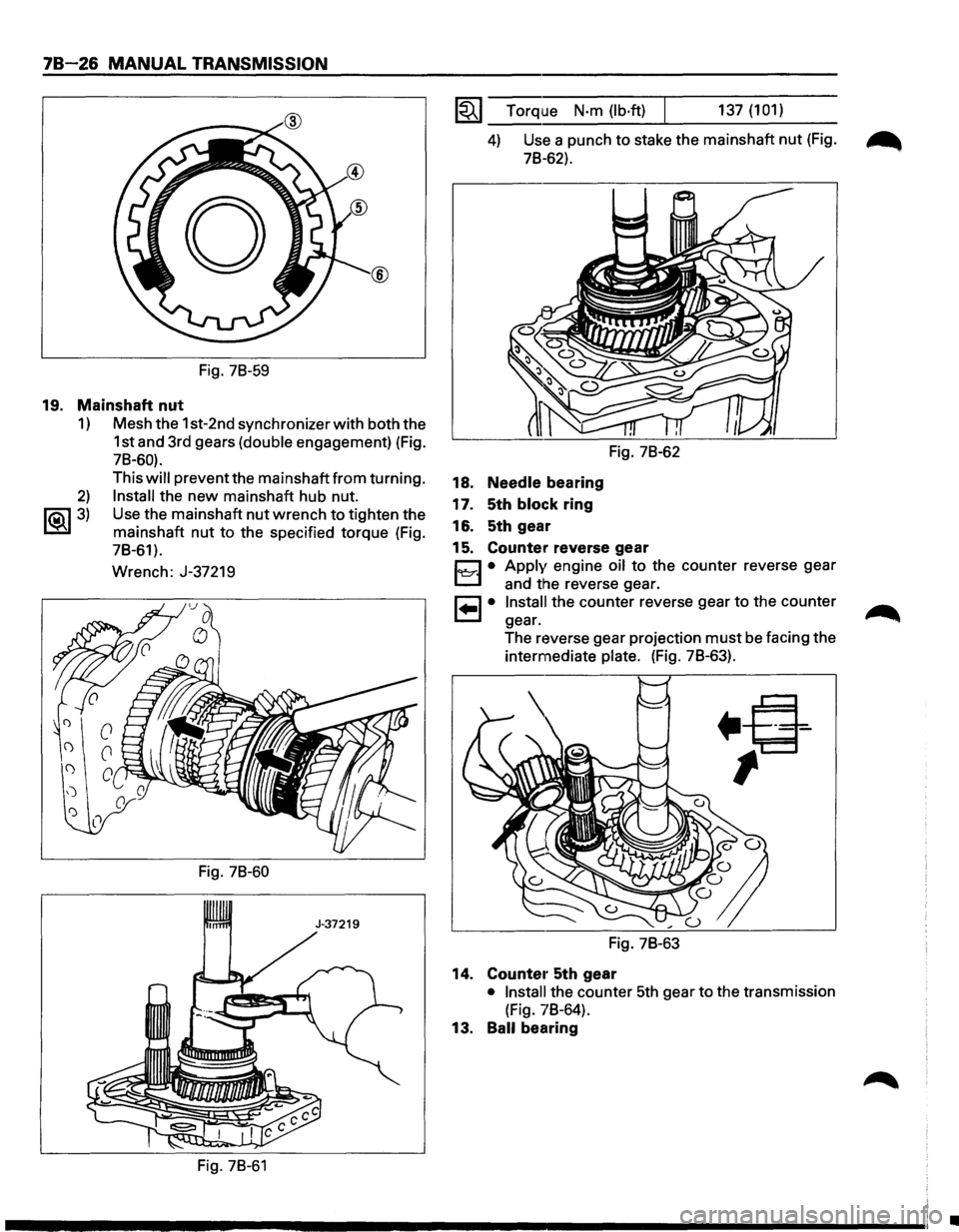
Fig. 78-59
19. Mainshaft nut
1) Mesh the 1st-2nd synchronizer with both the
1st and 3rd gears
(double engagement) (Fig.
78-60).
2)
~3)
This will prevent the mainshaft from turning.
Install the new mainshaft hub nut.
Use the mainshaft
nut wrench to tighten the
mainshaft
nut to the specified torque (Fig.
78-61).
Wrench: J-37219
Fig. 78-60
Fig. 78-61
1~1 Torque N·m (lb·ft) 137 (101)
4) Use a punch to stake the mainshaft nut (Fig. ~
78-62).
18. Needle bearing
17. 5th
block ring
16. 5th gear
Fig. 78-62
15. Counter reverse gear
Cl • Apply engine oil to the counter reverse gear
L.::::::.l and the reverse gear.
8 • Install the counter reverse gear to the counter
gear.
The reverse gear projection
must be facing the
intermediate
plate. (Fig. 78-63).
Fig. 78-63
14. Counte1· 5th gear
• Install the counter 5th gear to the transmission
(Fig. 78-64).
13. Ball bearing
•
Page 1118 of 1928
78-28 MANUAL TRANSMISSION
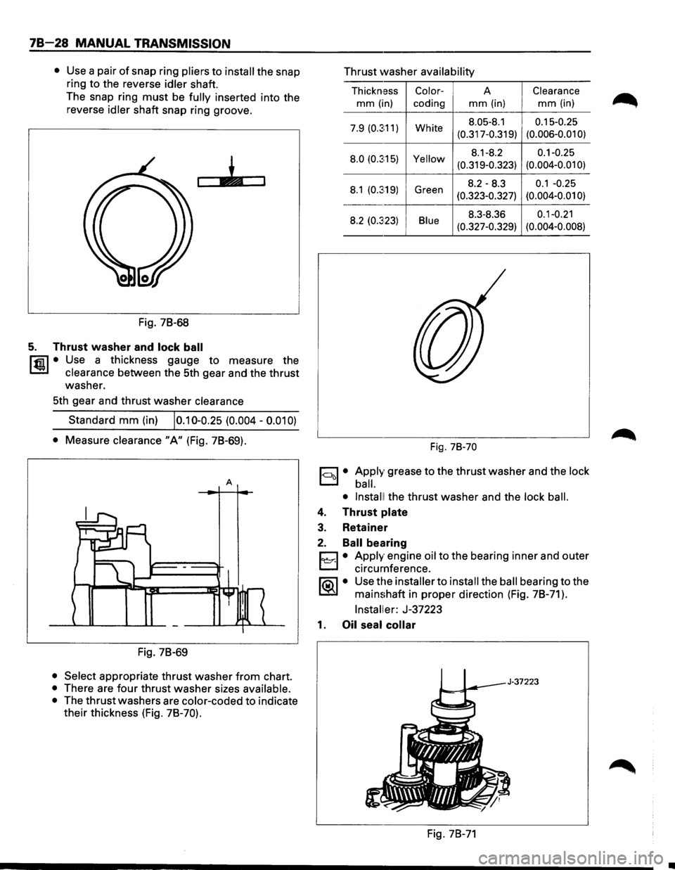
• Use a pair of snap ring pliers to install the snap
ring to the reverse
idler shaft.
The snap ring
must be fully inserted into the
reverse
idler shaft snap ring groove.
Fig. 78-68
5. Thrust washer and lock ball
l'fil • Use a thickness gauge to measure the
1.!::.1 clearance between the 5th gear and the thrust
washer.
5th gear and thrust washer
clearance
Standard mm (in) 10.10-0.25 (0.004 -0.01 0)
• Measure clearance "A" (Fig. 78-69).
A
Fig. 78-69
• Select appropriate thrust washer from chart.
• There are four thrust washer sizes available.
•
The thrust washers are color-coded to indicate
their thickness (Fig.
78-70).
Thrust washer availability
Thickn,ess Color-A Clearance
mm (in)
coding mm (in) mm (in)
7.9 (0.3:11) White 8.05-8.1 0.15-0.25
(0.317-0.319) (0.006-0.01
0)
8.0
(0.3:15) Yellow 8.1-8.2 0.1-0.25
(0.319-0.323) (0.004-0.01
0)
8.1 (0.3:19) Green 8.2-8.3 0.1 -0.25
(0.323-0.327) (0.004-0.01 0)
8.2 (0.323) Blue 8.3-8.36 0.1-0.21
(0.327-0.329) (0.004-0.008)
Fig. 78-70
1-ool • Apply grease to the thrust washer and the lock
ball.
• Install!
the thrust washer and the lock ball.
4. Thrust plate
3. Retainer
2. Ball bearing
D • Apply engine oil to the bearing inner and outer
~ circumference.
lia\1 • Use the installer to install the ball bearing to the
~ mainshaft in proper direction (Fig. 78-71 ).
Installer: J-37223
1. Oil seal collar
Fig. 78-71
•
Page 1124 of 1928
78-34 MANUAL TRANSMISSION
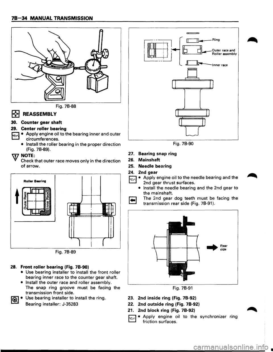
Fig. 78-88
l•!•l REASSEMBLY
30. Counter gear shaft
29. Center roller bearing
r:::::1 • Apply engine oil to the bearing inner and outer
L.:::.l circumferences.
• Install the roller bearing in the proper direction
(Fig. 78-89).
'q7 NOTE:
VI Check that outer race moves only in the direction
of arrow.
Roller Beering
t
Fig. 78-89
28. Front roller bearing (fig. 78-90)
• Use bearing installer to install the front roller
bearing inner race to the counter gear shaft.
• Install the outer race and roller assembly.
The snap ring groove must be facing the
transmission
front side.
1®..1• Use bearing installer to install the ring.
Bearing
installer: J-35283
=
rr=:=n--Ring
~ Outer race and ~Roller assembly
c:::Jb..-lnner race
Fig. 78-90
27. Bearing snap ring
26. Mainshaft
25. Needle bearing
24. 2nd gear
D • Apply engine oil to the needle bearing and the
L.:::.l 2nd gear thrust surfaces.
• Install the needle bearing and the 2nd gear to
the mainshaft.
r:;::] The 2nd gear dog teeth must be facing the
~ transmission rear side (Fig. 78-91 ) .
Fig. 78-91
23. 2nd inside ring (Fig. 78-92)
22. 2nd
outside ring (Fig. 78-92)
21. 2nd
bloc:k ring (Fig. 78-92)
.. Rear
side
D • Apply engine oil to the synchronizer ring
L.:::.l friction surfaces.
•
Page 1126 of 1928
78-36 MANUAL TRANSMISSION
Snap ring availability mm (in)
Thickness
Color-coding
1.80 (0.071)
White
1.85
(0.073) Yellow
1.90 (0.075)
Blue
•
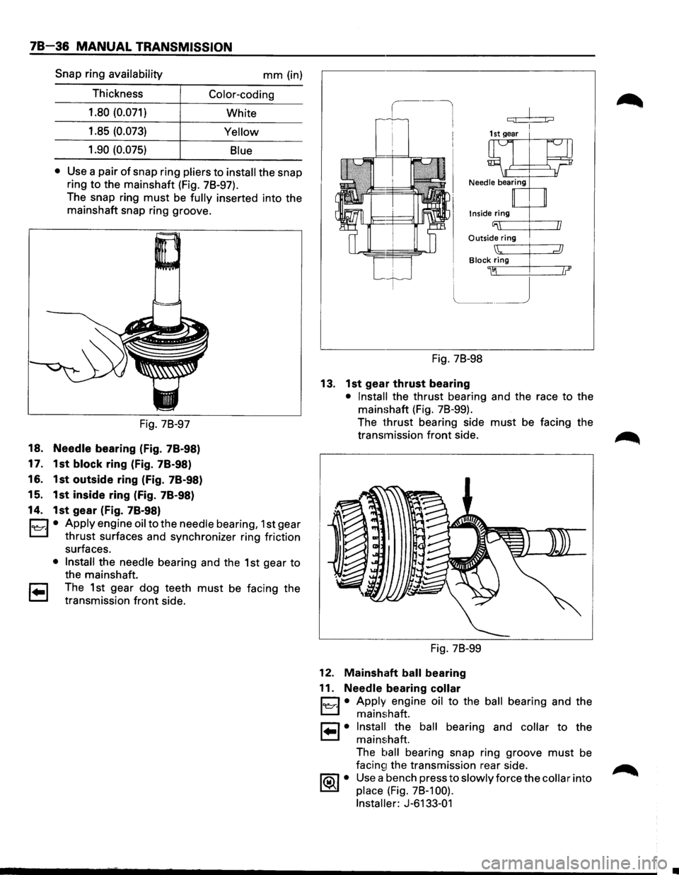
Use a pair of snap ring pliers to install the snap
ring
to the mainshaft (Fig. 78-97).
The snap ring
must be fully inserted into the
mainshaft snap ring groove.
Fig. 78-97
18. Needle bearing (Fig. 78-98)
17. 1st
block ring (Fig. 78-98)
16. 1st outside ring (Fig. 78-98)
15. 1st inside ring (Fig. 78-98)
14. 1st gear (Fig. 78-98)
C1 • Apply engine oil to the needle bearing, 1st gear
L::l thrust surfaces and synchronizer ring friction
surfaces.
• Install the needle bearing and the 1st gear to
the mainshaft.
1 .. 1 The 1st gear dog teeth must be facing the
transmission
front side.
c:;! j;::::J
Inside ring
Outside ring .
Block Zig I
~~ .
Fig. 78-98
13. 1st gear thrust bearing
• Install the thrust bearing and the race to the
mainshaft (Fig. 78-99).
The
thrust bearing side must be facing the
transmission
front side.
Fig. 78-99
12. Mainshaft ball bearing
11.
Needle bearing collar
1~·1 • Apply engine oil to the ball bearing and the
mainshaft.
1 .. 1• Install the ball bearing and collar to the
mainshaft.
The
ball bearing snap ring groove must be
facin~1 the transmission rear side.
1®..1 • Use a bench press to slowly force the collar into
place (Fig. 78-1 00).
Installer:
J-6133-01
Page 1127 of 1928
MANUAL TRANSMISSION 78-37
Fig. 78-100 Fig. 78-102
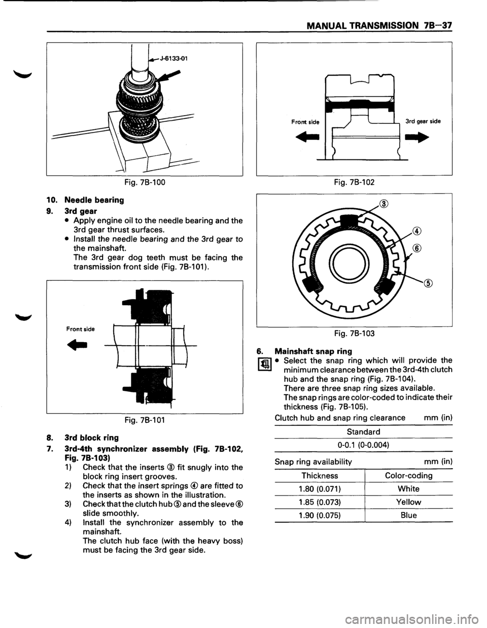
10. Needle bearing
9. 3rd gear
• Apply engine oil to the needle bearing and the
3rd gear
thrust surfaces.
• Install the needle bearing and the 3rd gear to
the mainshaft.
The 3rd gear dog teeth
must be facing the
transmission
front side (Fig. 78-101 ).
Front side
..
Fig. 78-101
8. 3rd block ring
7. 3rd-4th synchronizer assembly (Fig. 78-102,
Fig. 78·103)
1) Check that the inserts @ fit snugly into the
block ring insert grooves.
2) Check that the insert springs @ are fitted to
the inserts as shown in the illustration.
3) Check that the clutch hub@and the sleeve®
slide smoothly.
4) Install the synchronizer assembly to the
mainshaft.
The
clutch hub face (with the heavy boss)
must be facing the 3rd gear side. Fig.
78-103
6. Mainshaft snap ring
l"fil • Select the snap ring which will provide the
l..!l!l minimum clearance between the 3rd-4th clutch
hub and the snap ring (Fig. 78-1 04).
There are three snap ring sizes available.
The snap rings are color-coded to indicate their
thickness (Fig.
78-1 05).
Clutch
hub and snap ring clearance mm (in)
Standard
0-0.1 (0-0.004)
Snap
ring availability mm (in)
Thickness
Color-coding
1.80 (0.071)
White
1.85
(0.073) Yellow
1.90 (0.075) Blue