engine oil ISUZU TROOPER 1995 Workshop Manual
[x] Cancel search | Manufacturer: ISUZU, Model Year: 1995, Model line: TROOPER, Model: ISUZU TROOPER 1995Pages: 1928
Page 1212 of 1928
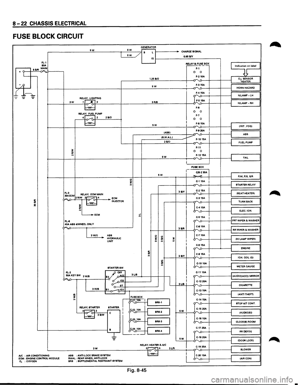
8-22 CHASSIS ELECTRICAL
FUSE BLOCK CIRCUIT
GENERATOR -------------------~s~w~------------~~s~w~--~~~~ r- / B L 1------CHARGE SIGNAL &W _/
FL-1 80A .-----, B 11.'1 MAIN
+ Lt--
l£h
~----/ IG~----------~O~.$~B/V~-----------,
3W REL~HT1NG 1J ---'"~L 3
RELA~PUMP 4 1...---. 12 2 B/0
1.25 B/0
SW
3RJ8
5W
~~~·~ F-1 0 0 F-2 10A
I F-315A
F-8
0 0 F-7 0 0 F-81SA
F-920A
9;nlaool
I
Oz SENSOR HEATER
HORN HAZARD
H/LAMP-LH
H/LAMP-RH
(FRT. FOG)
lABS) -I ABS
I ,--------__:<;;:R·.:.:W.::..Acc·L;;:-1 ____ ----Jv F-10 1SA 2 810
I
~ECM RELAY; ECM MAIN ¢~,...,..J>--+2'-'RIW~_::2~1-o.....-<:>-f-·4.:._ __ _. ~J~CTOR
L...-_.ECM
FL-t 40A ABS 4/WHEEL ONLY
"
.... ...
SW
5W
3 8IY
F-11 0 0 F-1215A
~------' FUSE BOX
CIB-2 30A ~.,.;
C-110A :
C-215A
C-31SA
C-410A
I
J
FUEL PUMP
TAIL
P/W, PIS. SIR
STARTER RELAY
(SEAT HEATER)
TURN BACK
ELEC.IGN.
e-s
15A 1 ""'-.0---t-----+----il FRT WIPER & WASHER
"""' -
I 3W/G
C-810A '---f-+----+.:3.:BIR::::..+---¢""''-£>---i-----f-----jl RR WIPER & WASHER
ABS HYORAULIC UNIT
STARTERSW
FL-2 _JJ OFF
~ ...
..:..AKEYSW 3 W/B ay ' o.N". 3UB
~~--~--~,~------~-0 ~~IG~2Y-----------~ o-: ST 3W/B 81 -.,IG1
FUSE BOX
I
I g1~ 1 J'-:::s:R:s-:1 =I RELAY; STARTER
STARTER I r-
L~---'~-j.t
I I 3UB
sw
C-710A
~';::--~--~-'---~~~HI~LA~M~P~W~IP~E~R~l~~ C-81SA ""'-'>--1---...__---i ENGINE
C-111SA I J~======~l IGN. COIL (G)
C-10 10A
C-1110A
k'-1:>----t----t
~==~I
METER GAUGE
""''-£>---f----------1 (AUDIO[ACC)) MIRROR
C-12 20A
::...1310A I
C-141SA -r"\'-1)----f----t
C-15 20A L,-.
CIGARETTE
(ANTITHEFT)
STOP A/T CONT.
(AUDIO[ B))
C-1810A """"-'-.0---f----------t_j CLOCK[B) ROOM
L---+------------------------iB lt~;_ ~=~~~:~:~::~~~: C-17 2SA I
G1820A
RR DEFOG
= sw (DOOR LOCK) RELAY; HEATER &A/C .:._ __________________ .:.:3~W'-'---------------------~2to~.....-4 3UR C-19 2SA ...... BLOWER
A/C : AIR CONDITIONING ECM : ENGINE CONTIIOL MODULE 0, :OXYGEN ABS
:ANTI-LOCK
BRAKE BYBTEM
RWAL: REAR WHEEL ANTI-LOCK BRB : SUPPLEMENTAL RESTRAINT SYSTEM
C-20 10A (AIR CON)
Fig. 8-45
•
Page 1214 of 1928
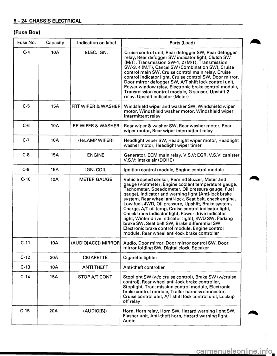
8-24 CHASSIS ELECTRICAL
(Fuse Box)
Fuse No.
Capacity Indication on label Parts (Load)
C-4 10A
ELEC.IGN. Cruise control unit, Rear defogger SW, Rear defogger
relay, Rear
defo9ger SW indicator light, Clutch SW
(M{T), Transmission SW-1, 2 (M!T), Transmission
SW-3, 4 (M{T), Cancel
SW (Combination SW), Cruise
control main
SW, Cruise control main relay, Cruise
control indicator light, Cruise control
SW, Door mirror,
Door mirror defogger SW, AfT shift lock control unit,
Power window relay, Electronic brake control module,
Transmission control module, G sensor, Upshift-2
relay, Upshift indicator (Meter)
C-5 15A FRTWIPER &WASHER
Windshield wipt~r and washer SW, Windshield wiper
motor, Windshit~ld washer motor, Windshield wiper
intermittent relay
C-6 10A RR WIPER & WASHER
Rear wiper & washer SW, Rear washer motor, Rear
wiper motor, Rear wiper intermittent relay
C-7 10A (H/LAMP WIPER) Headlight wiper SW, Headlight wiper motor, Headlight
washer motor, Headlight
wiper timer
C-8 15A ENGINE Generator, ECM main relay, V.S.V; EGA, V.S.V: canister,
V.S.V: intake air
(DOHC)
C-9 15A IGN. COIL Ignition control module, Engine control module
C-10 10A METER GAUGE Vehicle speed stmsor, Remind Buzzer, Meter and
gauge
(Voltmeter, Engine coolant temperature gauge,
Tachometer, Speedometer,
Oil pressure gauge, Fuel
gauge),
Indicator and warning light (Anti-lock brake
system, Rear wheel anti-lock, Seat belt, check engine,
Low fuel, 4WD,
Oil pressure, Upshift, Brake system,
Charge,
AfT oil temp, Cruise control indicator light,
Check trans indicator light,
Power drive indicator
light,
Winter drive indicator light), 4WD SW, Parking
brake SW, Seat belt SW, Brake differential SW
Electronic brake control module, Engine control
module, Rear wheel anti-lock brake controller
C-11 10A (AUDIO[ACCJ) MIRROR Audio, Door mirror, Door mirror control SW, Door
mirror folding SW, Digital clock, Speaker
C-12 20A CIGARETTE Cigarette lighter
C-13 10A
ANTI THEFT Anti-theft controller
C-14 15A
STOP AfT CONT Stoplight SW (w/o cruise control), Brake SW (w/cruise
control), Rear wheel anti-lock brake controller,
Stoplight, Transmission control module, Electronic
brake control module, Trailer harness connector,
Cruise control unit,
AfT shift lock control unit, Lockup
off relay
C-15
20A (AUDIO[B]) Horn,
Horn relay, Horn SW, Hazard warning light SW,
Flasher unit, Anti-theft horn, Hazard warning light,
Audio
•
Page 1215 of 1928
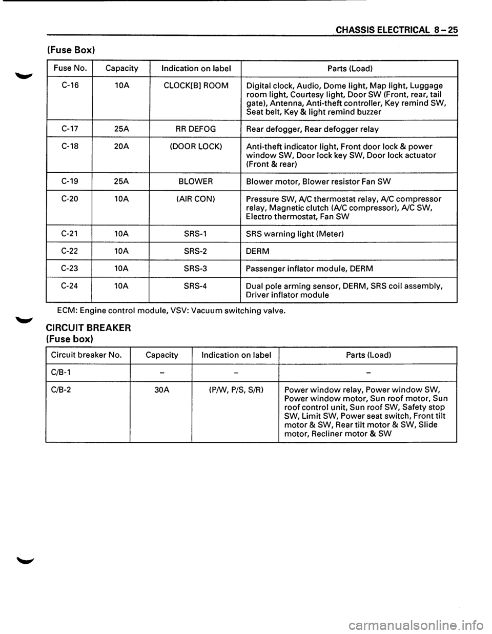
CHASSIS ELECTRICAL 8-25
(fuse Box)
Fuse No.
Capacity Indication on label Parts
(Load)
C-16
10A
CLOCK[B] ROOM Digital clock, Audio, Dome light, Map light, Luggage
room light, Courtesy light, Door SW (Front, rear, tail
gate), Antenna, Anti-theft controller, Key remind SW,
Seat belt, Key & light remind buzzer
C-17 25A RR DEFOG Rear defogger, Rear defogger relay
C-18 20A (DOOR LOCK) Anti-theft indicator light, Front door lock & power
window SW, Door lock key SW, Door lock actuator
(Front
& rear)
C-19 25A BLOWER Blower motor, Blower resistor Fan SW
C-20 10A (AIR CON) Pressure SW, A/C thermostat relay, A/C compressor
relay, Magnetic clutch
(A/C compressor), A/C SW,
Electro thermostat, Fan SW
C-21 10A SRS-1 SRS warning light (Meter)
C-22 10A SRS-2 DERM
C-23
10A SRS-3 Passenger inflator module, DERM
C-24
10A SRS-4 Dual pole arming sensor, DERM, SRS coil assembly,
Driver inflator module
ECM: Engine control module, VSV: Vacuum switching valve.
CIRCUIT BREAKER
(fuse box)
Circuit breaker No.
C/B-1
C/B-2
Capacity
-
30A
Indication on label
-
(P/W, P/S, S/R)
Parts (Load)
-
Power window relay, Power window SW,
Power window motor, Sun roof motor, Sun
roof control unit, Sun roof SW, Safety stop
SW, Limit SW, Power seat switch, Front tilt
motor & SW, Rear tilt motor & SW, Slide
motor, Recliner
motor & SW
Page 1220 of 1928
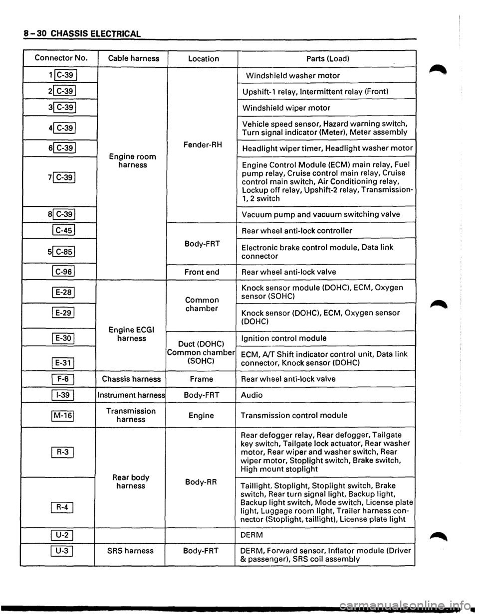
8-30 CHASSIS ELECTRICAL
Connector No.
Cable harness
Location Parts (load)
1jC-39I Windshield washer motor
21 C-391 Upshift-1 relay, Intermittent relay (Front)
31 C-391 Windshield wiper motor
41 C-39j Vehicle speed
sensor, Hazard warning switch,
Turn
signal indicator (Meter), Meter assembly
sl C-391 Fender-RH Headlight wiper timer, Headlight washer motor
Engine room
harness Engine Control Module (ECM)
main relay, Fuel
71 C-391 pump relay, Cruise control main relay, Cruise
control main switch, Air Conditioning relay,
Lockup off relay, Upshift-2 relay, Transmission-
1, 2 switch
al C-391 Vacuum pump and vacuum switching valve
I C-451 Rear wheel anti-lock controller
sl c-asl
Body-FRT Electronic brake control module, Data link
connector
I C-961 Front end Rear wheel
anti-lock valve
I E-281 Knock sEmsor module (DOHC), ECM, Oxygen
Common sensor (SOHC)
I E-291 chamber Knock sensor (DOHC), ECM, Oxygen sensor
(DOHC)
Engine
ECGI
I E-30 I harness Duct (DOHC) Ignition control
module
Common chamber
ECM, AfT Shift indicator control unit, Data link
I
E-311 (SOHC) connector, Knock sensor (DOHC)
~ Chassis harness Frame
Rear wheel anti-lock valve
11-391 Instrument
harness
Body-FRT Audio
IM-161 Transmission
Engine Transmission control module harness
Rear defogger
relay, Rear defogger, Tailgate
~
key switch, Tailgate lock actuator, Rear washer
motor, A:ear wiper and washer switch, Rear
wiper motor, Stoplight switch, Brake switch,
High
mount stoplight
Rear body Body-RR
harness Taillight, Stoplight, Stoplight switch, Brake
switch,
near turn signal light, Backup light,
~
Backup light switch, Mode switch, License plate
light, Lu!;)gage room light, Trailer harness con-
nector
(Stoplight, taillight), License plate light
~ DERM
00 SRS harness Body-FRT
DERM, Forward sensor, Inflator module (Driver
& passenger),
SRS coil assembly
•
Page 1382 of 1928
8-192 CHASSIS ELECTRICAL
TRANSMISSION CONTROL MODULE (TCM)
GENERAL DESCRIPTION
The circuit consists of the starter switch, TCM, mode switch, brake switch, speed sensor, kick down switch,
Power and
Winter switches, Throttle Position (TP) sensor, Engine Control Module (ECM), barometer sensor,
adapter case, main case,
warning light (CHECK TRANS, NT OIL TEMP) and indicator light (WINTER DRIVE,
POWER DRIVE).
The TCM, based on the predetermined shifting characteristics and lockup operating valve, provides the
optimum shifting control to the varying vehicle running condition. The following input signals are sent to the
TCM: select lever position from the mode switch, running mode from the POWER & WINTER switches,
throttle opening from the TP sensor, vehicle speed from the vehicle speed sensor and engine speed from the
ECM are sent to the TCM. After receiving these signals, the TCM determines the vehicle running condition,
and
it sends output signals to each solenoid to control shifting.
When the
TCC solenoid is engaged, the lockup mechanism operates.
The shift
solenoid 2.3 and 1.2/3.4 selects the shift gear position.
The force
motor controls the line pressure to improve shifting.
Also, when the TCM detects an abnormal signal from the transmission or sensor, it will cause the "CHECK
TRANS"
light on the warning box to flash in order to inform the driver of the malfunction.
Refer to section 7 A "AUTOMATIC TRANSMISSION" for details.
•
Page 1478 of 1928
8-288 CHASSIS ELECTRICAL
METER AND WARNING/INDICATOR LIGHT
GENERAL DESCRIPTION
The circuit consists of the starter switch, meter assembly, vehicle speed sensor, clutch switch, transmission
switch, lighting switch,
turn signal switch, thermo unit, oil pressure unit, Engine Control Module, fuel tank unit,
4WD
SW, oil pressure switch, parking brake switch, brake fluid switch, seat belt switch and illumination
controller.
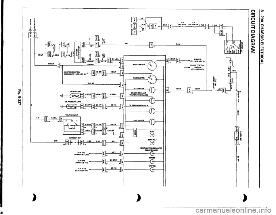
The meter ASM contains the speedometer, tachometer, voltmeter, engine coolant temperature gauge, oil
pressure gauge, fuel gauge and warning/indicator lights.
The meter warning/indicator lights and
their bulb sockets are a unit, they are installed from the back of the
speedometer assembly.
Page 1480 of 1928
•
, ce· CX) I w w .....
..
~ m
0
z
0 0 <
m
n
"'
-1
:D
"'
:z:
= ~~ :;; )
O.SIItll 2B
O.&B
ID
-,~
r
-•3
'
.. '
'
' ' IGNITION
CONTROL
MODULECTO
PAGE
S.S1,
531
ECMCASI
(TO PAGE
11-51,
531
TCMihl (TO PAGE
8-1t41
TCMIA111 (TO PAGE
11-1141
~[~} m[i] ~ .:. II
. 0 j[~}l
I'lL,
II"
:----~
.. :~.:,._
:
fill
:~
~~~~ I -··
.!., -
SPEEOOMETER TACHOMETER VOLTMETER ENGINE
COOLANT
TEMPERATURE
GAUGE
OIL PRESSUSRE
GAUGE
FUEL
GAUGE MALFUNCT10N
INDICATOR
lCHECKENGWEI
POWEll -TER
)
O.SL
ECMIDIII
ITO PAGE
11-51,
531
CRUISE
CONTROL UNITI131 ITO PAGE
11-1741
O.SLJY ;;
~ ~ '!' ;;: ~ ~ n ~ ~ )
n -:JJ n c =i c -)> G) :JJ )> 3:
co I N CD 0 (") :.t: > Cl) Cl) Cl) m ,.... m Q , n )> ,....
Page 1485 of 1928
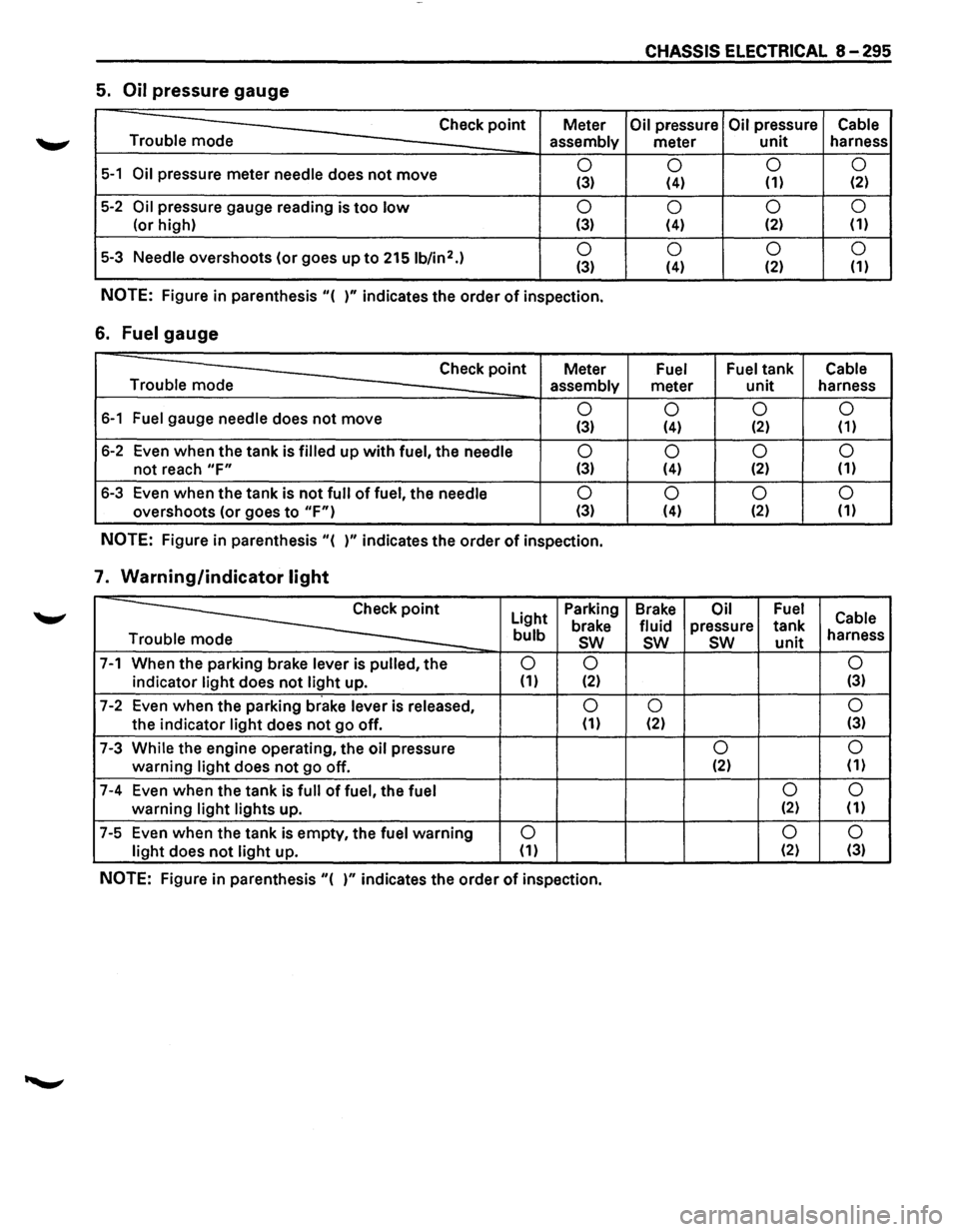
CHASSIS ELECTRICAL 8-295
5. Oil pressure gauge
Check point Meter Oil pressure Oil pressure Cable
Trouble mode
assembly meter unit harness
5-1 Oil pressure meter needle does not move 0
0 0
0 (3) (4) (1) (2)
5-2 Oil pressure
gauge reading is too low 0
0 0
0
(or
high) (3) (4) (2) (1)
5-3 Needle overshoots
(or goes up to 2151b/in2.) 0
0 0 0 (3) (4) (2)
(1)
NOTE: Figure
in parenthesis "( )" indicates the order of inspection.
6. Fuel gauge
Check point Meter Fuel Fuel tank Cable
Trouble mode assembly
meter unit harness
6-1 Fuel gauge needle does not move 0
0 0 0 (3) (4) (2) (1)
6-2 Even when the tank is filled up with fuel, the needle 0
0 0
0
not reach "F" (3) (4) (2)
(1)
6-3
Even when the tank is not full of fuel, the needle 0
0 0
0
overshoots (or goes to "F") (3) (4) (2) (1)
NOTE: Figure
in parenthesis "( )" indicates the order of inspection.
7. Warning/indicator light
~
Light Parking
Brake Oil Fuel Cable brake fluid pressure tank bulb sw sw sw unit harness
e
7-1 When the parking brake lever is pulled, the 0 0 0
indicator light does not light up. (1) (2) (3)
7-2 Even
when the parking brake lever is released, 0 0 0
the indicator light does not go off. (1) (2) (3)
7-3 While the engine operating,
the oil pressure 0 0
warning light does not go
off. (2)
(1)
7-4 Even
when the tank is full of fuel, the fuel 0 0
warning light lights
up. (2) (1)
7-5 Even
when the tank is empty, the fuel warning 0 0
0
light does not light up. (1) (2)
(3)
NOTE: Figure in parenthesis "( )" indicates the order of inspection.
Page 1496 of 1928
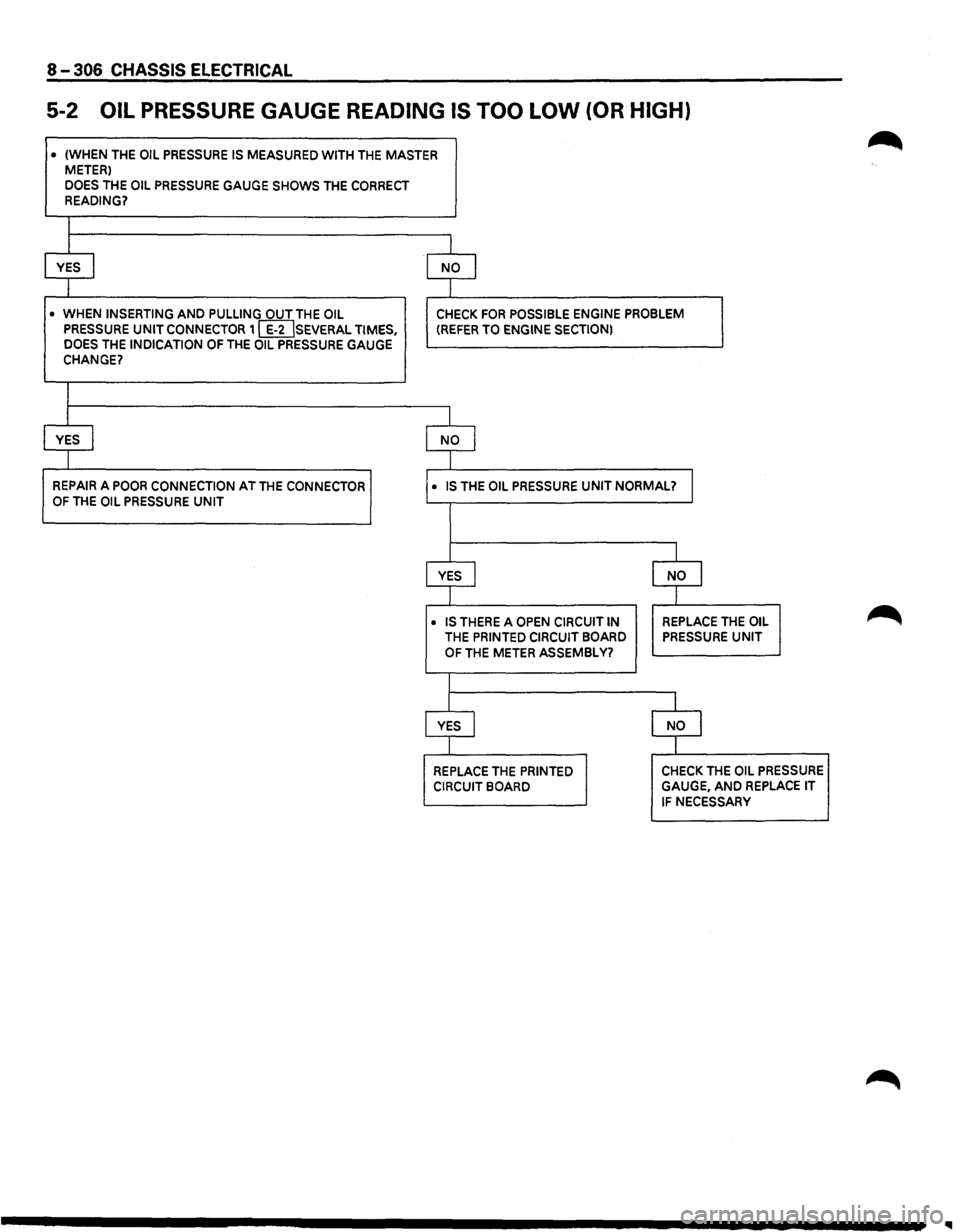
8-306 CHASSIS ELECTRICAL
5-2 OIL PRESSURE GAUGE READING IS TOO LOW (OR HIGH)
• (WHEN THE OIL PRESSURE IS MEASURED WITH THE MASTER METER)
DOES THE OIL PRESSURE GAUGE SHOWS THE CORRECT READING?
I
I
YES I NO I
I
• WHEN INSERTING AND PULLING OUT THE OIL CHECK FOR POSSIBLE ENGINE PROBLEM PRESSURE UNIT CONNECTOR 1 [IDSEVERAL TIMES, (REFER TO ENGINE SECTION) DOES THE INDICATION OF THE OIL PRESSURE GAUGE CHANGE?
I
I
YES I NO I
I
REPAIR A POOR CONNECTION AT THE CONNECTOR • IS THE OIL PRESSURE UNIT NORMAL? I OF THE OIL PRESSURE UNIT
I
YES J NO I
I
• IS THERE A OPEN CIRCUIT IN REPLACE THE OIL
THE PRINTED CIRCUIT BOARD PRESSURE UNIT
OF THE METER ASSEMBLY?
I
YES I NO I
I
REPLACE THE PRINTED CHECK THE OIL PRESSURE
CIRCUIT BOARD GAUGE, AND REPLACE IT
IF NECESSARY
Page 1503 of 1928
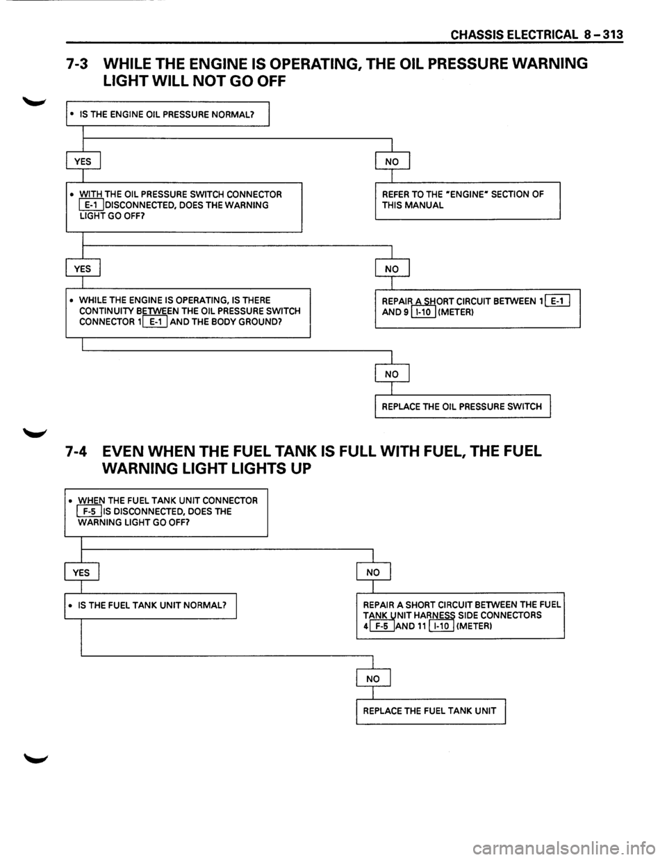
CHASSIS ELECTRICAL 8-313
7-3 WHILE THE ENGINE IS OPERATING, THE OIL PRESSURE WARNING
LIGHT WILL
NOT GO OFF
• IS THE ENGINE OIL PRESSURE NORMAL? I
I
I I
YES I NO I
I I
• WITH THE OIL PRESSURE SWITCH CONNECTOR REFER TO THE "ENGINE" SECTION OF
~DISCONNECTED, DOES THE WARNING THIS MANUAL LIGHT GO OFF?
I
I I
YES I NO I
I I
• WHILE THE ENGINE IS OPERATING, IS THERE REPAIRctTIORT CIRCUIT BETWEEN 1 [ill CONTINUITY BETWEEN THE OIL PRESSURE SWITCH AND 9 1-10 (METER) CONNECTOR 1~ AND THE BODY GROUND?
I
I
NO I
I
REPLACE THE OIL PRESSURE SWITCH I
7-4 EVEN WHEN THE FUEL TANK IS FULL WITH FUEL, THE FUEL
WARNING LIGHT LIGHTS UP
• WHEN THE FUEL TANK UNIT CONNECTOR
[EIJ1s DISCONNECTED, DOES THE WARNING LIGHT GO OFF?
l
YES I NO I
I
• IS THE FUEL TANK UNIT NORMAL? I REPAIR A SHORT CIRCUIT BETWEEN THE FUEL
TiNK JNIT HARNESS SIDE CONNECTORS 4 F-5 AND 11 [I!QJ (METER)
1
NO I
I
REPLACE THE FUEL TANK UNIT I