engine oil ISUZU TROOPER 1995 Workshop Manual
[x] Cancel search | Manufacturer: ISUZU, Model Year: 1995, Model line: TROOPER, Model: ISUZU TROOPER 1995Pages: 1928
Page 1129 of 1928
MANUAL TRANSMISSION 78-39
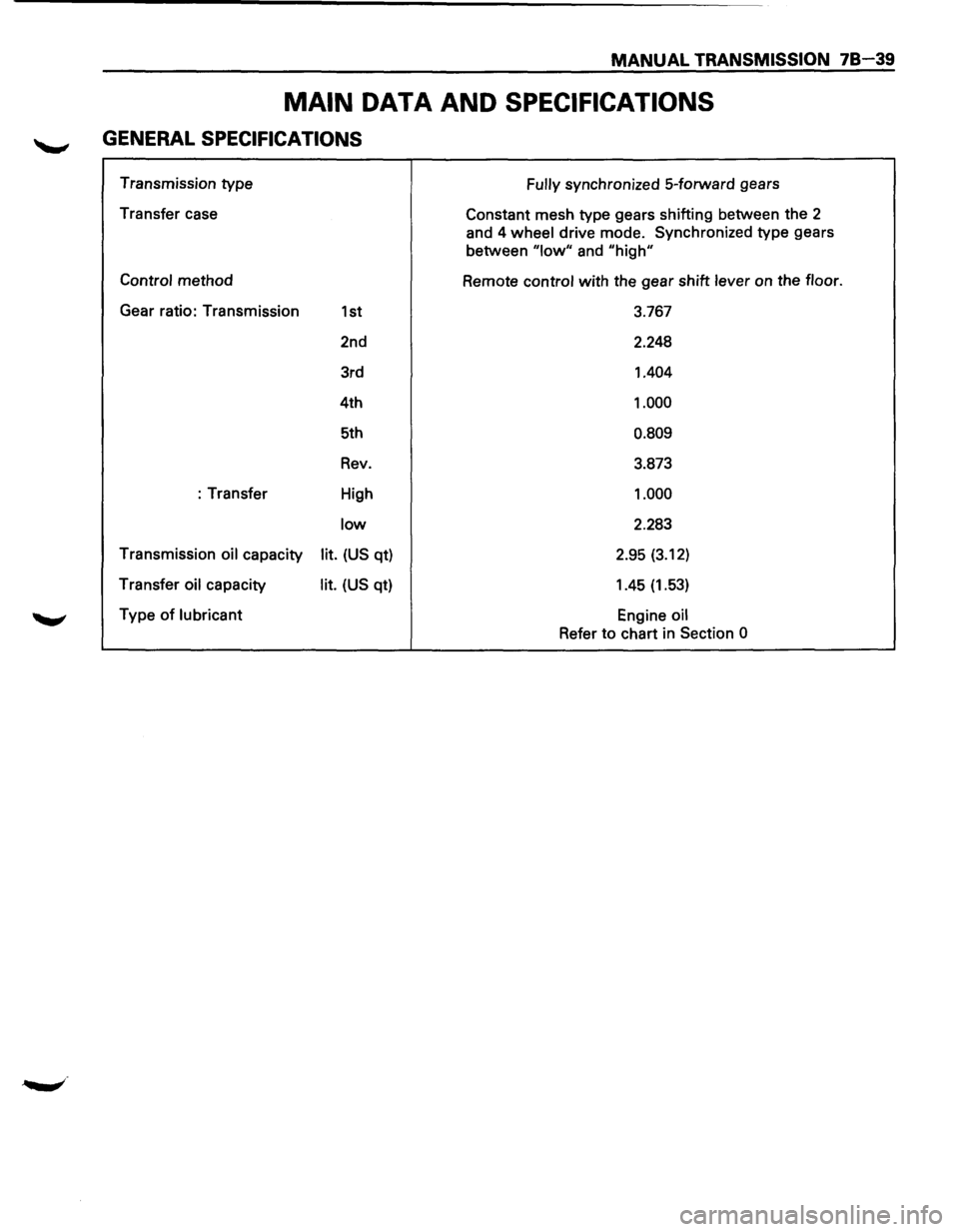
MAIN DATA AND SPECIFICATIONS
GENERAL SPECIFICATIONS
Transmission type
Transfer case
Control method
Gear ratio: Transmission
1st
2nd
3rd
4th
5th
Rev.
:Transfer High
low
Transmission oil capacity lit. (US qt)
Transfer
oil capacity lit. (US qt)
Type
of lubricant Fully
synchronized
5-forward gears
Constant mesh type gears shifting between the
2
and 4 wheel drive mode. Synchronized type gears
between
"low" and "high"
Remote control with the gear shift lever on the floor.
3.767
2.248
1.404
1.000
0.809
3.873
1.000
2.283
2.95
(3.12)
1.45 (1.53)
Engine oil
Refer to chart in Section 0
Page 1139 of 1928
CLUTCH 7C-5
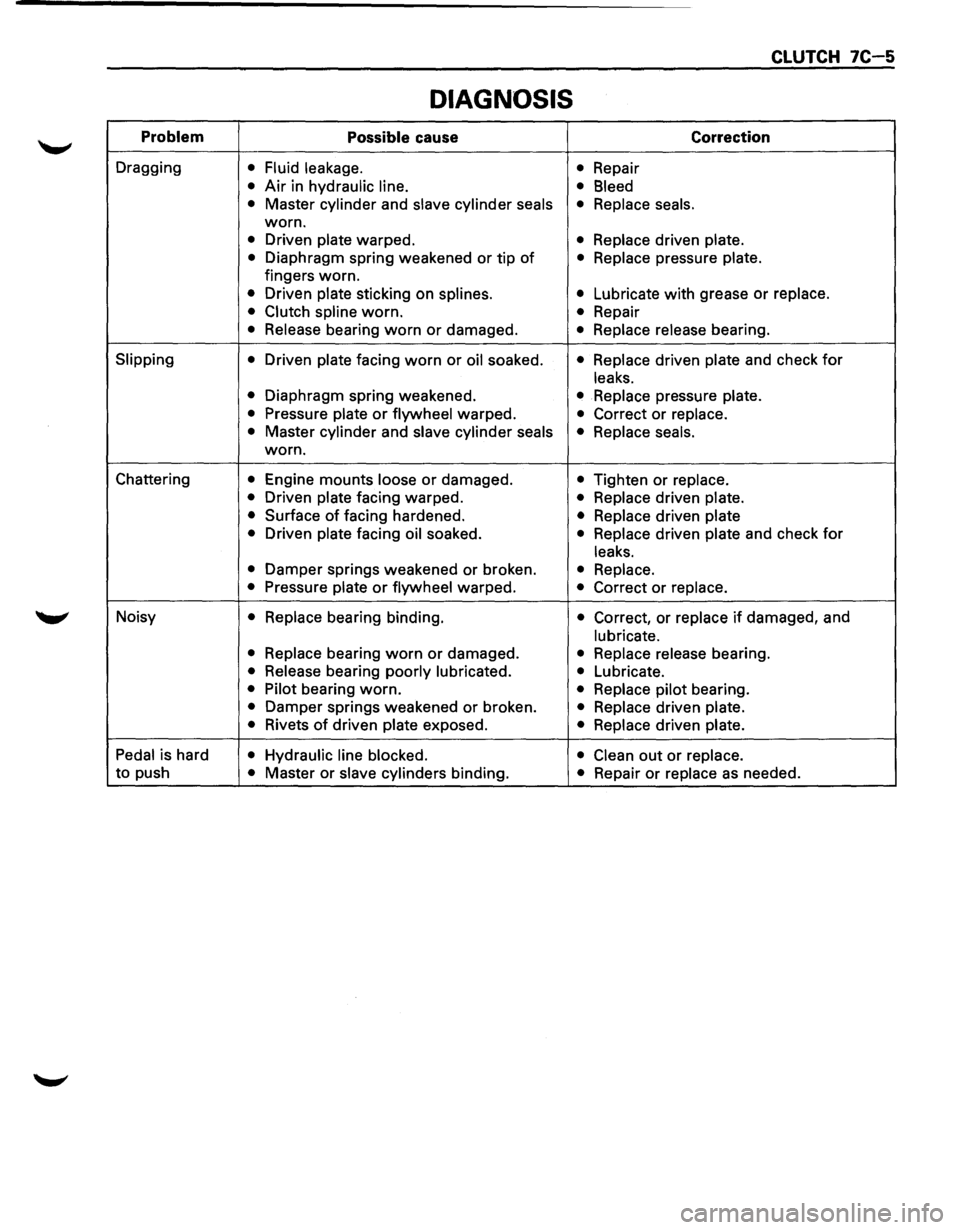
DIAGNOSIS
Problem Possible cause Correction
Dragging • Fluid leakage.
• Repair
• Air in hydraulic line.
• Bleed
•
Master cylinder and slave cylinder seals • Replace seals.
worn.
• Driven plate warped. • Replace driven plate.
•
Diaphragm spring weakened or tip of • Replace pressure plate.
fingers worn.
• Driven plate sticking on splines. • Lubricate with grease or replace.
• Clutch spline
worn. • Repair
• Release bearing worn or damaged. • Replace release bearing.
Slipping
• Driven plate facing worn or oil soaked. • Replace driven plate and check for
leaks.
•
Diaphragm spring weakened. • Replace pressure plate.
•
Pressure plate or flywheel warped. • Correct or replace.
•
Master cylinder and slave cylinder seals
• Replace seals.
worn.
Chattering
• Engine mounts loose or damaged. • Tighten or replace.
•
Driven plate facing warped. • Replace driven plate.
•
Surface of facing hardened. • Replace driven plate
•
Driven plate facing oil soaked. • Replace driven plate and check for
leaks.
•
Damper springs weakened or broken. • Replace.
•
Pressure plate or flywheel warped. • Correct or replace.
Noisy • Replace bearing binding. • Correct, or replace if damaged, and
lubricate.
• Replace
bearing worn or damaged. • Replace release bearing.
• Release bearing poorly lubricated.
• Lubricate.
• Pilot bearing worn. • Replace pilot bearing.
• Damper springs weakened or broken. • Replace driven plate.
•
Rivets of driven plate exposed. • Replace driven plate.
Pedal
is hard • Hydraulic line blocked.
• Clean out or replace.
to push • Master or slave cylinders binding. • Repair or replace as needed.
Page 1164 of 1928
70-6 TRANSFER CASE
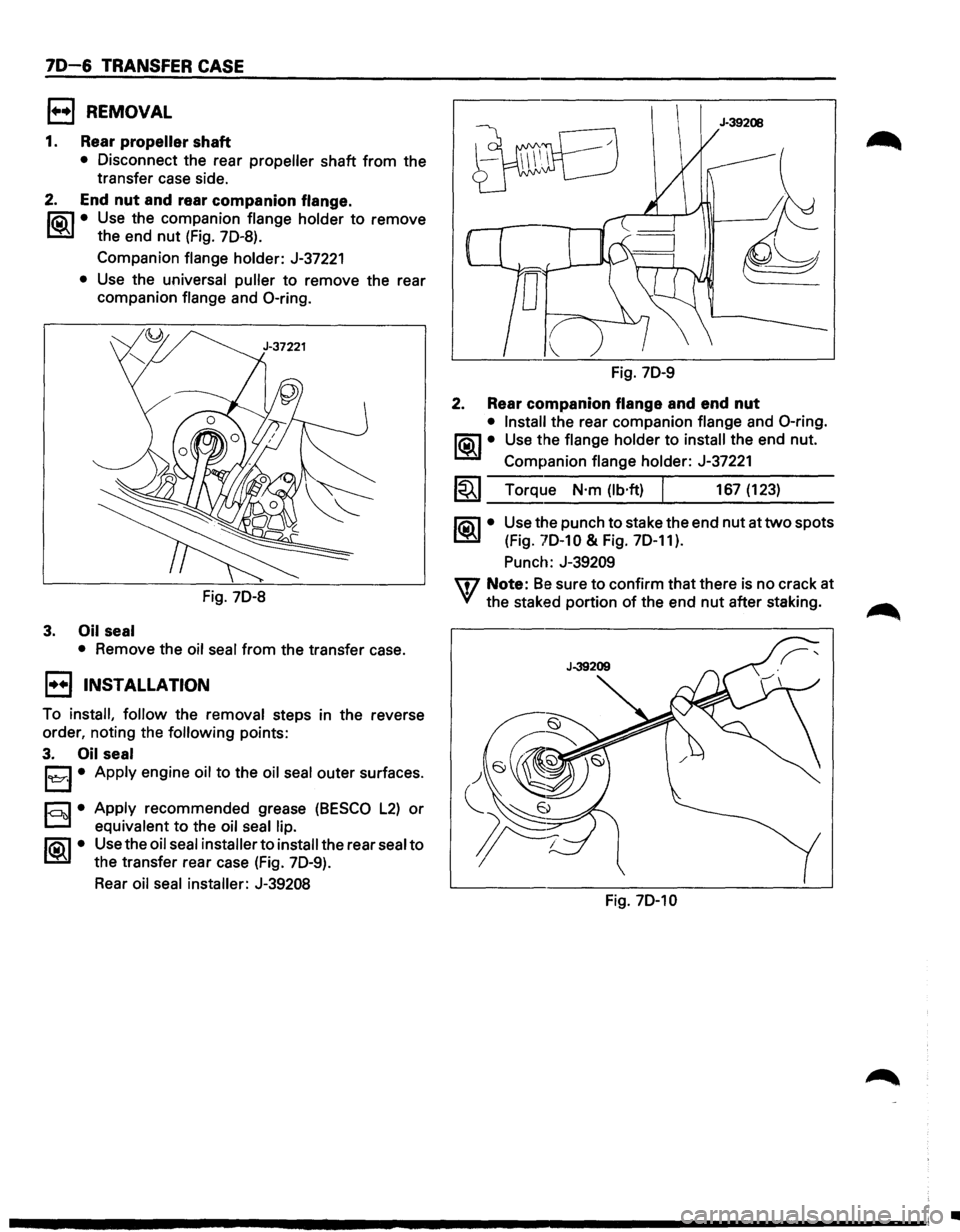
EJ REMOVAL
1. Rear propeller shaft
• Disconnect the rear propeller shaft from the
transfer case side.
2. End nut and rear companion flange.
li5\l • Use the companion flange holder to remove
~ the end nut (Fig. 70-8).
Companion flange holder: J-37221
• Use the universal puller to remove the rear
companion flange and 0-ring.
Fig. 70-8
3. Oil seal
•
Remove the oil seal from the transfer case.
1••1 INSTALLATION
To install, follow the removal steps in the reverse
order, noting the
following points:
3. Oil seal
l
D equivalent to the oil seal lip.
li5\l • Use the oil seal installer to install the rear seal to
~ the transfer rear case (Fig. 70-9).
Rear oil seal installer: J-39208
Fig. 70-9
2. Rear companion flange and end nut
• Install the rear companion flange and 0-ring.
l<9l..l• Use the flange holder to install the end nut.
Companion flange holder:
J-37221
1~1 Torque N·m (lb·ft) I 167 (123)
~·
Use the punch to stake the end nut at two spots
(Fig.
70-10 & Fig. 70-11).
Punch: J-39209
m Note: Be sure to confirm that there is no crack at
VI the staked portion of the end nut after staking.
Fig. 70-10
•
Page 1170 of 1928

70-12 TRANSFER CASE
5. Speedometer drive gear
6. Ball
7. Collar
8. Bearing snap ring
• Use a pair of snap ring pliers to remove the
snap ring.
9. Ball bearing
10. Rear output shaft
l'iC\1 • Use a bench press and the bearing remover to
~ remove the ball bearing (Fig. 70-24).
Bearing remover: J-22912-01
11. Transfer rear case (with oil seal)
Fig. 70-24
Wtl INSPECTION AND REPAIR
Refer to "TRANSFER CASE ASSEMBLY" in this Section
for inspection and repair.
l•!•l REASSEMBLY
11. Transfer rear case (with oil seal)
Oil seal
replacement
• Remove the oil seal from the transfer rear case.
D • Apply engine oil to the oil seal outer surfaces. 12::::]
§1•
~·
Fill in recommended grease (BESCO L2) or
equivalent in the oil seal lip.
Use the oil seal installer to install the rear oil
seal
to the transfer rear case (Fig. 70-25).
Oil
seal installer: J-39208
Fig. 70-25
10.
Rear output shaft
9. Ball bearing
l'iC\1 • Use the ball bearing installer and the adapter to
~ instalil the ball bearing (Fig. 70-26).
Ball
bearing installer: J-37223
Adap1ter: J-37486
Fig. 70-26
8. Bearing snap ring
7. Collar
6. Ball
J.37486
5. Speedometer drive gear (Fig. 70-27)
4. Ball bearing
liC\1 • Use the ball bearing installer to install the ball
~ bearing (Fig. 70-28).
Ball
be1aring installer: J-37223
•
Page 1181 of 1928
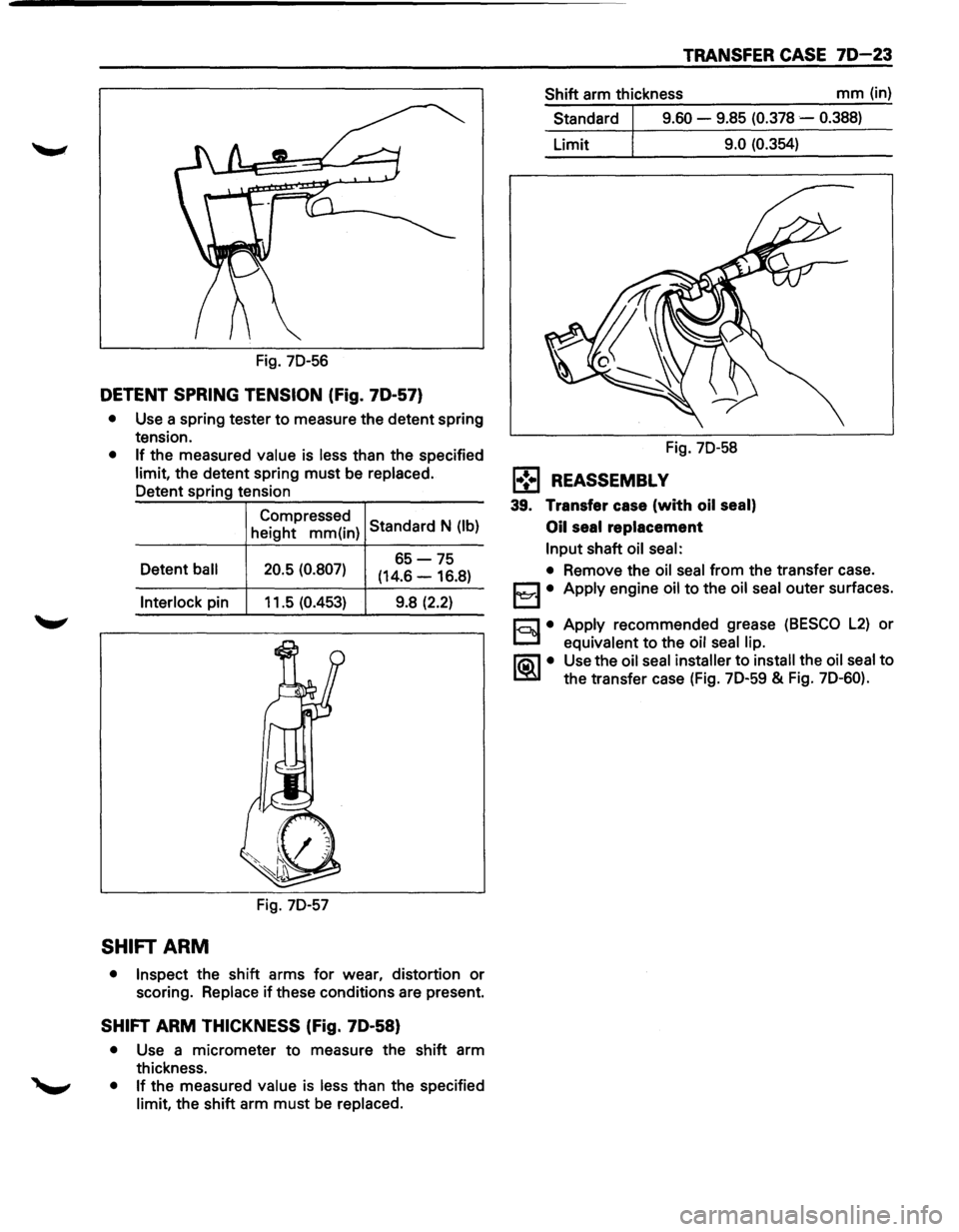
Fig. 7D-56
DETENT SPRING TENSION (Fig. 70-57)
• Use a spring tester to measure the detent spring
tension.
• If the measured value is less than the specified
limit, the detent spring must be replaced.
Detent spring tension
Compressed Standard N (lb)
height mm(in)
Detent
ball 20.5 (0.807) 65-75
(14.6 -16.8)
Interlock pin 11.5 (0.453) 9.8 (2.2)
Fig. 7D-57
SHIFT ARM
•
Inspect the shift arms for wear, distortion or
scoring. Replace
if these conditions are present.
SHIFT ARM THICKNESS (Fig. 70-58)
• Use a micrometer to measure the shift arm
thickness.
• If the measured value is less than the specified
limit, the shift arm must be replaced.
TRANSFER CASE 70-23
Shift arm thickness mm (in)
Standard
9.60 - 9.85 (0.378 -0.388)
Limit 9.0 (0.354)
Fig. 7D-58
l•!•l REASSEMBL V
39. Transfer case (with oil seal)
Oil
seal replacement
Input shaft oil seal:
• Remove the oil seal from the transfer case.
j3 • Apply engine oil to the oil seal outer surfaces.
r.:;::'l • Apply recommended grease (BESCO L2) or
D equivalent to the oil seal lip.
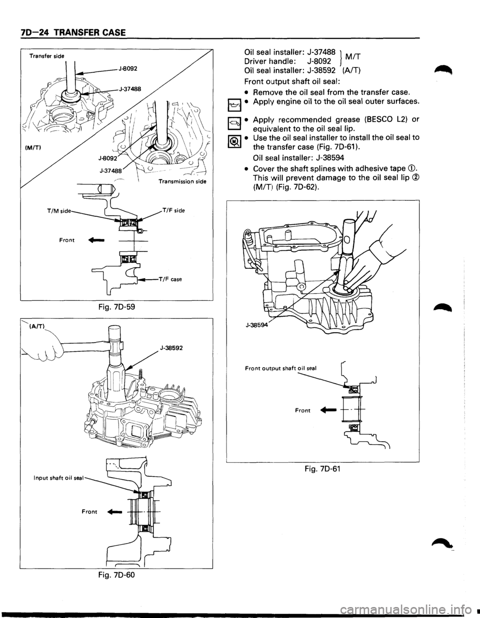
li:\1 • Use the oil seal installer to install the oil seal to
~ the transfer case (Fig. 7D-59 & Fig. 7D-60).
Page 1182 of 1928
70-24 TRANSFER CASE
Transfer side
(M/TI
--...___ (A/TI
T/M side
Front
Input shaft oil seal
Fig. 70-59
Fig. 70-60
lc::: I \f~ /(\A\~
t \l(
~~~
-------'"'-~'~
Transmission side
T/F side
Oil seal installer: J-37488 } MIT
Driver handle: J-8092
Oil
seal installer: J-38592 (AIT)
Front
output shaft oil seal:
• Remove the oil seal from the transfer case.
j
~·
Apply recommended grease (BESCO L2) or
equivalent to the oil seal lip.
Use the oil seal
installer to install the oil seal to
the transfer case (Fig.
70-61 ).
Oil sHal installer: J-38594
• Cover the shaft splines with adhesive tape CD.
This will prevent damage to the oil seal lip ®
(MIT) (Fig. 70-62).
Fig. 70-61
•
Page 1184 of 1928
70-26 TRANSFER CASE
Fig. 70-66
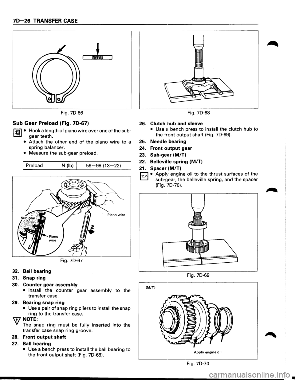
Sub Gear Preload (Fig. 70-67)
~·
Hook a length of piano wire over one of the sub
gear teeth.
• Attach the other end of the piano wire to a
spring
balancer.
•
Measure the sub-gear preload.
Preload
32. Ball bearing
31.
Snap ring
N (lb)
Fig. 70-67
30. Counter gear assembly
59-98 (13-22)
• Install the counter gear assembly to the
transfer case.
29. Bearing snap ring
• Use a pair of snap ring pliers to install the snap
ring
to the transfer case.
W NOTE:
~ The snap ring must be fully inserted into the
transfer case snap ring groove.
28. Front output shaft
27. Ball bearing
• Use a bench press to install the ball bearing to
the front output shaft (Fig. 70-68).
Fig. 70-68
26. Clutch hub and sleeve
• Use a bench press to install the clutch hub to
the front output shaft (Fig. 70-69).
25. Needle bearing
24.
Front output gear
23. Sub-gear
(MIT)
22. Belleville spring (MIT)
21. Spacer (M/T)
C1 • Apply engine oil to the thrust surfaces of the
t.::::::J sub-gear, the belleville spring, and the spacer
(Fig.
70-70).
Fig. 70-69
(M/TI
Apply engine oil
Fig. 70-70
•
Page 1187 of 1928
TRANSFER CASE 70-29
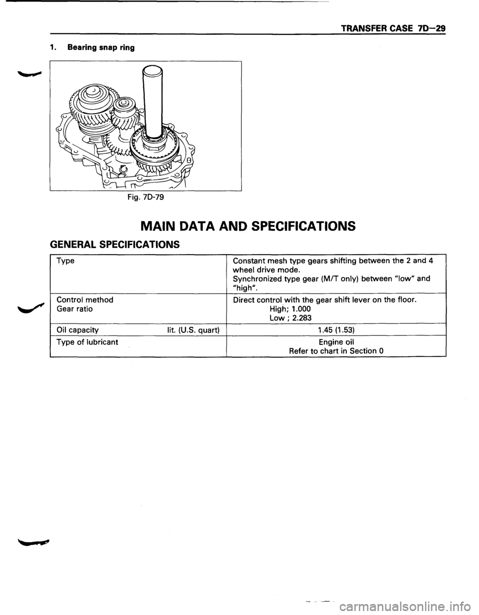
1. Bearing snap ring
Fig. 70-79
MAIN DATA AND SPECIFICATIONS
GENERAL SPECIFICATIONS
Type Constant mesh type gears shifting between the 2 and 4
wheel drive mode.
Synchronized type gear
(M/T only) between "low" and
"high".
Control method Direct control with the gear shift lever on the floor.
Gear ratio
High; 1.000
Low; 2.283
Oil capacity lit. (U.S. quart) 1.45 (1.53)
Type of lubricant Engine oil
Refer to chart in Section
0
Page 1210 of 1928
8-20 CHASSIS ELECTRICAL
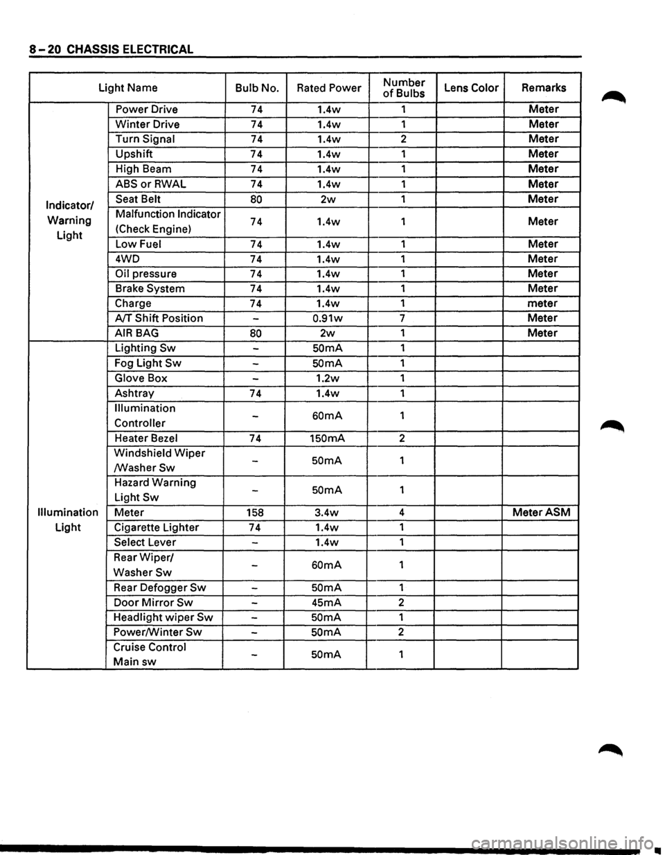
Light Name Bulb No. Rated Power Number Lens Color Remarks of Bulbs
Power Drive 74 1.4w 1
Meter
Winter Drive 74 1.4w
1 Meter
Turn Signal 74 1.4w 2 Meter
Upshift
74 1.4w 1 Meter
High Beam
74 1.4w 1 Meter
ABSorRWAL 74 1.4w 1 Meter
Indicator/ Seat Belt 80 2w 1 Meter
Warning Malfunction Indicator 74 1.4w
1 Meter
Light (Check
Engine)
Low Fuel 74 1.4w 1 Meter
4WD
74 1.4w 1 Meter
Oil pressure 74 1.4w 1 Meter
Brake System 74 1.4w 1 Meter
Charge 74 1.4w 1
meter
A/T Shift Position -0.91w 7 Meter
AIR BAG 80 2w 1 Meter
Lighting Sw -SOmA 1
Fog Light
Sw -SOmA 1
Glove Box -1.2w 1
Ashtray
74 1.4w 1
Illumination
60mA 1 -Controller
Heater Bezel 74 1SOmA 2
Windshield
Wiper SOmA 1 -/WasherSw
Hazard Warning SOmA 1 -Light Sw
Illumination Meter 158 3.4w 4 MeterASM
Light
Cigarette Lighter
74 1.4w
1
Select Lever -1.4w 1
Rear
Wiper/ 60mA 1 -WasherSw
Rear Defogger Sw -SOmA 1
Door
Mirror Sw -45mA 2
Headlight
wiper Sw -SOmA 1
Power/Winter
Sw -SOmA 2
Cruise Control
SOmA 1 -Main sw
II
Page 1211 of 1928
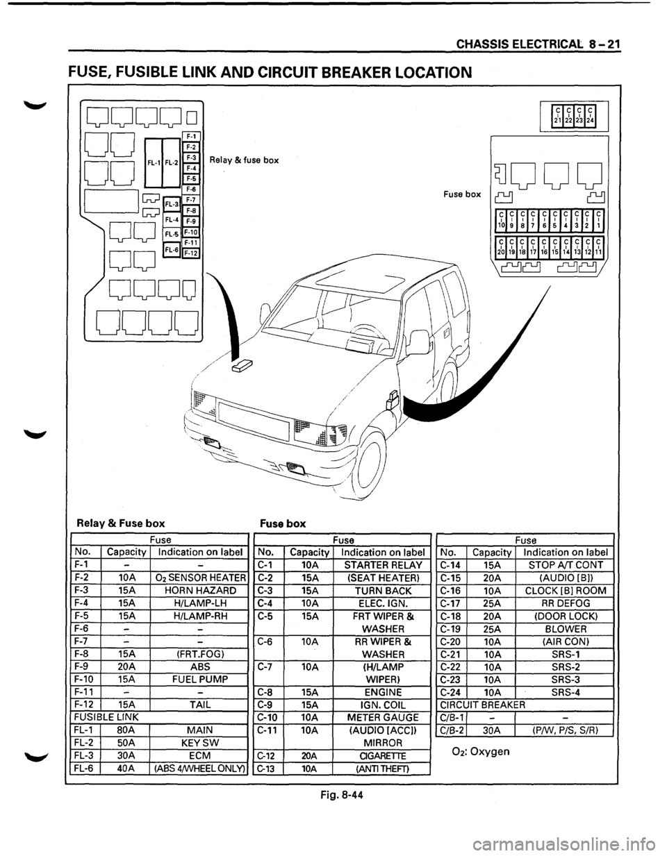
CHASSIS ELECTRICAL 8-21
FUSE, FUSIBLE LINK AND CIRCUIT BREAKER LOCATION
ooooo 112~12~1~1~1
00 E
EEr 00 ~
Relay & fuse box
SJOOO 7-6
I lw ;;::;~ Fuse box ~ ~
1l1~~ ~lff~UIH~Inll
w~ F-a FL-4 ~
00 FL·S~ r---, F-11 'l2~J1~ 1~1&11~11~1,\l~31hl1~1
0
0
FL-6 'F-i2
I' ~
\a~ a~;
0000
0000
I ~
l/
~
j
~/~/ e:;?' v II I / / .I / /
('-/ .
~~
-~-~;,a~ ~~ --.:_
~~~~ -
Relay & Fuse box Fuse box
Fuse
Fuse Fuse
No. Capacity Indication on label No. Capacity Indication on label No. Capacity Indication on label
F-1 --C-1 10A STARTER RELAY
C-14 15A STOP A!f CONT
F-2 10A 02 SENSOR HEATER C-2 15A (SEAT HEATER)
C-15 20A (AUDIO [8))
F-3
15A HORN HAZARD C-3 15A
TURN BACK C-16 10A CLOCK (8] ROOM
F-4
15A H/LAMP-LH C-4 10A ELEC.IGN. C-17 25A RR DEFOG
F-5
15A H/LAMP-RH C-5
15A FRTWIPER & C-18 20A (DOOR LOCK)
F-6 --WASHER C-19
25A BLOWER
F-7
- -C-6 10A RRWIPER & C-20 10A (AIR
CON)
F-8
15A (FRT.FOG) WASHER C-21 10A SRS-1
F-9 20A ABS C-7 10A (H/LAMP C-22 10A SRS-2
F-10
15A FUEL PUMP WIPER) C-23 lOA SRS-3
F-11 -
-C-8 15A ENGINE C-24 10A SRS-4
F-12
15A TAIL C-9 15A IGN. COIL CIRCUIT BREAKER
FUSIBLE
LINK
C-10 10A METER GAUGE
C/8-1 --FL-1 80A MAIN C-11 10A
(AUDIO IACC])
C/8-2 30A (P/W, P/S, S/R)
FL-2 50 A KEYSW MIRROR
FL-3 30A ECM C-12 20A CIGARETTE 02: Oxygen
FL-6 40A (ASS 4/WHEEL ONLY) C-13 10A (ANTI THEFT)
Fig. 8-44