display ISUZU TROOPER 1995 Repair Manual
[x] Cancel search | Manufacturer: ISUZU, Model Year: 1995, Model line: TROOPER, Model: ISUZU TROOPER 1995Pages: 1928
Page 779 of 1928
CD
DRIVEABILITV AND EMISSIONS 6E2-83
• ENGINE IDLING.
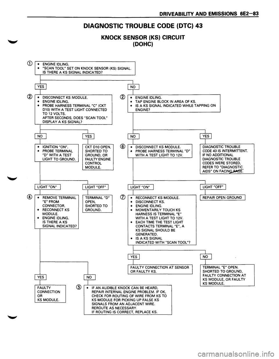
DIAGNOSTIC TROUBLE CODE (DTC) 43
KNOCK SENSOR (KS) CIRCUIT
(DOHC)
• "SCAN TOOL" SET ON KNOCK SENSOR (KS} SIGNAL. IS THERE A KS SIGNAL INDICATED?
~ $
• DISCONNECT KS MODULE. ® • ENGINE IDLING.
• ENGINE IDLING. • TAP ENGINE BLOCK IN AREA OF KS. • PROBE HARNESS TERMINAL "C" (CKT • IS A KS SIGNAL INDICATED WHILE TAPPING ON
D10} WITH A TEST LIGHT CONNECTED
ENGINE?
TO 12 VOLTS. AFTER SECONDS, DOES "SCAN TOOL"
DISPLAY A KS SIGNAL?
$ ~ ~ ~ • IGNITION "ON". CKT D10 OPEN, @ • DISCONNECT KS MODULE. DIAGNOSTIC
TROUBLE
• PROBE TERMINAL SHORTED TO • PROBE HARNESS TERMINAL "D" CODE 43 IS INTERMITTENT. "D" WITH A TEST
GROUND, OR WITH A TEST LIGHT TO 12V. IF NO ADDITIONAL
LIGHT TO GROUND. FAULTY ENGINE DIAGNOSTIC TROUBLE
CONTROL CODES WERE STORED,
MODULE.
REFER TO "DIA~= AIDS" ON FAGIN .
I I
LIGHT "ON" I LIGHT "OFF" I LIGHT "ON" j LIGHT "OFF" I
I
I
• REMOVE TERMINAL TERMINAL "D" (J) • RECONNECT KS MODULE. REPAIR
OPEN GROUND I "E" FROM
OPEN, • DISCONNECT KS . CONNECTOR.
SHORTED TO • ENGINE IDLING.
• RECONNECT KS GROUND. • MOMENTARILY TOUCH KS MODULE.
HARNESS IS TERMINAL "E" • ENGINE IDLING. WITH A TEST LIGHT TO 12V. IS THERE A KS • EACH TIME THE TEST LIGHT
SIGNAL INDICATED?
CONTACTS TERMINAL "E", A KS SIGNAL SHOULD BE GENERATED. • IS A KS SIGNAL
INDICATED WITH "SCAN TOOL"?
~ $
~
FAULTY CONNECTION AT SENSOR TERMINAL "E" OPEN. OR FAULTY KS. SHORTED
TO GROUND,
~
FAULTY CONNECTION AT KS MODULE, OR FAULTY KS MODULE. FAULTY @ • IF AN AUDIBLE KNOCK CAN BE HEARD, CONNECTION
REPAIR INTERNAL ENGINE PROBLEM. IF OK, OR CHECK FOR ROUTING OF WIRE FROM KS TO KS MODULE. KS MODULE FOR PICKING UP FALSE KS SIGNALS FROM AN ADJACENT WIRE.
REROUTE AS NECESSARY. IF ROUTING IS CORRECT, REPLACE KS.
Page 780 of 1928
6E2-84 DRIVEABILITY AND EMISSIONS
DIAGNOSTIC TROUBLE CODE (DTC) 44
HEATED OXYGEN SENSOR (H02S) CIRCUIT
(LEAN HEATED OXYGEN SENSOR (H02S) SIGNAL INDICATED)
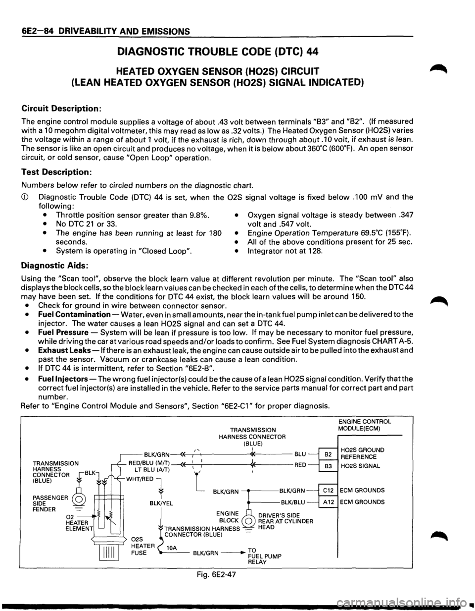
Circuit Description:
The engine control module supplies a voltage of about .43 volt between terminals "83" and "82". (If measured
with a
10 megohm digital voltmeter, this may read as low as .32 volts.) The Heated Oxygen Sensor (H02S) varies
the
voltage within a range of about 1 volt, if the exhaust is rich, down through about .1 0 volt, if exhaust is lean.
The sensor is like an open circuit and produces no voltage, when it is below about 360°C (600°F). An open sensor
circuit,
or cold sensor, cause "Open Loop" operation.
Test Description:
Numbers below refer to circled numbers on the diagnostic chart.
CD Diagnostic Trouble Code (DTC) 44 is set, when the 02S signal voltage is fixed below .1 00 mV and the
following:
• Throttle
position sensor greater than 9.8%.
• No DTC 21 or 33. • Oxygen signal voltage is steady between .347
volt and .547 volt.
•
The engine has been running at least for 180 •
seconds. • • System is operating in "Closed Loop". •
Engine Operation Temperature 69SC (155°F).
All of the above conditions present for 25 sec .
Integrator not at 128 .
Diagnostic Aids:
Using the "Scan tool", observe the block learn value at different revolution per minute. The "Scan tool" also
displays
the block cells, so the block learn values can be checked in each ofthe cells, to determine when the DTC 44
may have been set.
If the conditions for DTC 44 exist, the block learn values will be around 150.
•
Check for ground in wire between connector sensor.
• Fuel Contamination-Water, even in small amounts, near the in-tank fuel pump inlet can be delivered to the
injector. The water causes a
lean H02S signal and can set a DTC 44.
• Fuel Pressure-System will be lean if pressure is too low. If may be necessary to monitor fuel pressure,
while driving the car at various road speeds and/or loads to confirm. See Fuel System diagnosis CHART A-5.
• Exhaust Leaks -lfthere is an exhaust leak, the engine can cause outside air to be pulled into the exhaust and
past the sensor.
Vacuum or crankcase leaks can cause a lean condition.
• If DTC 44 is intermittent, refer to Section "6E2-8".
• Fuel
Injectors-The wrong fuel injector(s) could be the cause of a lean H02S signal condition. Verify that the
correct
fuel injector(s) are installed in the vehicle. Refer to the service parts manual for correct part and part
number.
Refer
to "Engine Control Module and Sensors", Section "6E2-C1" for proper diagnosis.
TRANSMISSION
HARNESS
CONNECTOR
~BLK1
TRANSMISSION
HARNESS CONNECTOR
(BLUE) I /' BL~GRN~r-~----------~-------BLU
RED/BLU (MfT) --(( 1
1 ; « RED
(BLUE) ~
PASSENGER Q SIDE
LT BLU (A/T) L
WHT/RED 1
P:::l=t=t1 l BL~GRN ----.-----BL~GRN
BLK!YEL BL~BLU FENDER 02 --·S HEATER ELEMENT l
ENGINE
DRIVER'S SIDE BLOCK REAR AT CYLINDER
TRANSMISSION HARNESS _ HEAD CONNECTOR (BLUE)
10A -----BL~GRN ____ .,.... ~3EL PUMP RELAY
Fig. 6E2-47
ENGINE CONTROL
MODULE(ECM)
H02SGROUND REFERENCE
H02SSIGNAL
ECM GROUNDS
ECM GROUNDS
..
Page 781 of 1928
DRIVEABILITY AND EMISSIONS 6E2-85
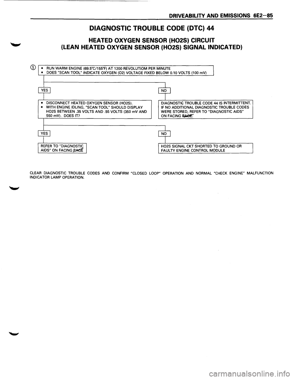
DIAGNOSTIC TROUBLE CODE (DTC) 44
HEATED OXYGEN SENSOR (H02S) CIRCUIT
(LEAN HEATED OXYGEN SENSOR (H02S) SIGNAL INDICATED)
(j) •
RUN WARM ENGINE (69SC/155'F) AT 1200 REVOLUTIOM PER MINUTE
• DOES "SCAN TOOL" INDICATE OXYGEN (02) VOLTAGE FIXED BELOW 0.10 VOLTS (100 mV)
• DISCONNECT HEATED OXYGEN SENSOR (H02S).
• WITH ENGINE IDLING, "SCAN TOOL" SHOULD DISPLAY
H02S BETWEEN .35 VOLTS AND .55 VOLTS (350 mV AND 550 mV). DOES IT?
DIAGNOSTIC TROUBLE CODE 44 IS INTERMITTENT. IF NO ADDITIONAL DIAGNOSTIC TROUBLE CODES WERE STORED, REFER TO "DIAGNOSTIC AIDS" ON FACING I?,Aer.
H02S SIGNAL CKT SHORTED TO GROUND OR FAULTY ENGINE CONTROL MODULE
CLEAR DIAGNOSTIC TROUBLE CODES AND CONFIRM "CLOSED LOOP" OPERATION AND NORMAL "CHECK ENGINE" MALFUNCTION
INDICATOR LAMP OPERATION.
Page 783 of 1928
DRIVEABILITY AND EMISSIONS 6E2-87
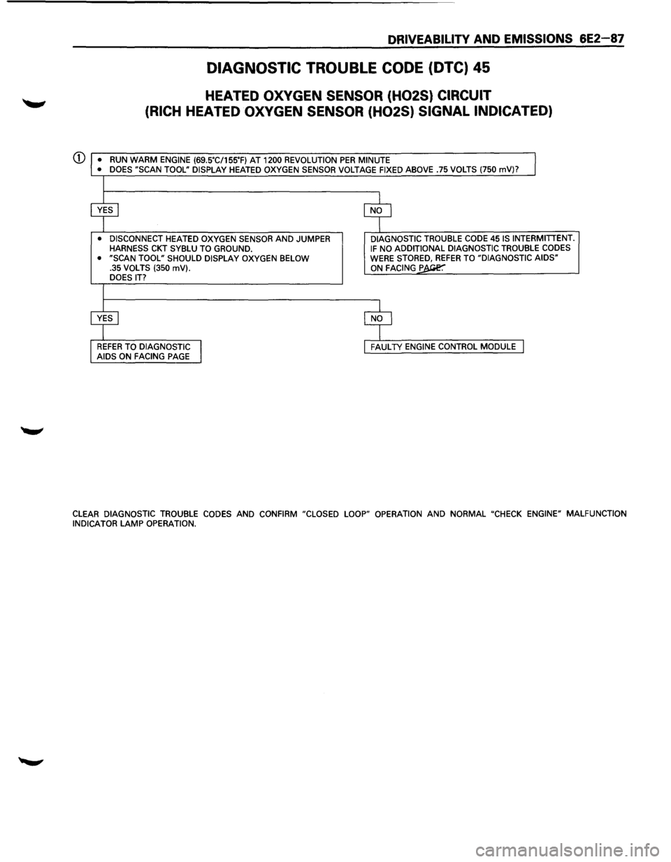
DIAGNOSTIC TROUBLE CODE (DTC) 45
HEATED OXYGEN SENSOR (H02S) CIRCUIT
(RICH
HEATED OXYGEN SENSOR (H02S) SIGNAL INDICATED)
Q) • RUN WARM ENGINE (69.5"C/155"F) AT 1200 REVOLUTION PER MINUTE
• DOES "SCAN TOOL" DISPLAY HEATED OXYGEN SENSOR VOLTAGE FIXED ABOVE .75 VOLTS (750 mV)?
• DISCONNECT HEATED OXYGEN SENSOR AND JUMPER HARNESS CKT SYBLU TO GROUND.
• "SCAN TOOL" SHOULD DISPLAY OXYGEN BELOW
.35 VOLTS (350 mV). DOES IT?
DIAGNOSTIC TROUBLE CODE 45 IS INTERMITTENT. IF NO ADDITIONAL DIAGNOSTIC TROUBLE CODES WERE STORED, REFER TO "DIAGNOSTIC AIDS" ON FACING P
CLEAR
DIAGNOSTIC TROUBLE CODES AND CONFIRM "CLOSED LOOP" OPERATION AND NORMAL "CHECK ENGINE" MALFUNCTION
INDICATOR LAMP OPERATION.
Page 800 of 1928
6E2-1 04 DRIVEABILITV AND EMISSIONS
Engine Coolant Temperature (ECT) Sensor
A "Scan tool" displays engine temperature in degrees
centigrade. After engine is started, the temperature
should rise steadily to about 90°C then stabilize when
thermostat opens. If the engine has not been run for
several hours (overnight), the engine coolant
temperature (ECT) and intake air temperature (IAT)
readings should be close to each other. A fault in the
ECT sensor circuit should set a diagnostic trouble code
(DTC) 14. The DTC charts also contain a chart to check
for sensor resistance values relative to temperature.
Intake Air Temperature (IAT) Sensor
A "Scan tool" displays temperature of the air entering
the engine and
should read close to ambient air
temperature when engine
is cold, and rise as under
hood temperature increases.
If the engine has not
been run for several hours (overnight), the IAT sensor
temperature and
ECT readings should be close to each
other. A
failure in the IAT sensor circuit should set a
DTC 23. The DTC charts also contain a chart to check
for sensor resistance values relative to temperature.
Heated Oxygen Sensor (H02S)
The "Scan tool" has several positions that will indicate
the state
of the exhaust gases, Oxygen voltage,
integrator, and block learn. See "Scan tool" position
information in
"Introduction", "Driveability and
Emission," in this section.
A
problem in the oxygen sensor circuit, or fuel system,
should set a DTC 13 (open circuit), DTC 44 (lean
indication)/DTC 45 (rich indication). Refer to
applicable chart, if any of these DTC(s) were stored in
memory.
Throttle Position (TP) Sensor
A "Scan tool" displays throttle position in volts. On 3.2L
engine, Throttle position
(TP) sensor voltage should
read below 0.85 volts, with throttle closed and ignition
"ON", or at idle. Voltage should increase at a steady
rate
as throttle is moved toward wide open throttle.
The Engine
Control Module (ECM) has the ability to
auto-zero the TP sensor voltage if it is below about 0.85
volts. This means that any voltage less than 0.85 volts
will
be determined by the ECM to be 0% throttle.
Some
"Scan tools" have the ability to read the throttle
angle and should read 0%, when the throttle is closed.
A failure in the TP sensor or circuit should set a DTC 21.
Manifold Absolute Pressure (MAP) Sensor
"Scan tool" displays manifold pressure in volts. Low
pressure (high vacuum) reads a
low voltage, while a
high pressure
(low vacuum) reads a high voltage. A
failure in the Manifold Absolute Pressure (MAP) sensor
circuit
should set a DTC 33 and using the chart will find
the cause
of the problem. A DTC 33 may be set if a
rough or unstable
idle exists. CHART C-1 D can also be
used
to check MAP sensor.
Vehicle Speed Sensor (VSS)
A "Scan tool" reading should closely match with
speedometer reading with drive wheels turning. A
failure in the vehicle speed sensor circuit should set a
DTC 24.
AIR CONDITIONING (A/C) Request Signal
When air conditioning in "ON", the "Scan tool" should
indicate air conditioning "ON".
See
"Air Conditioning Compressor Clutch Control
System",
Section "6E2-C1 0" for A/C electrical system
diagnosis.
Power Steering Pressure (PSP) Switch
A "Scan tool" should read "OFF" normally, and "ON"
with high pressure. This reading may vary with
different "Scan tools". Refer to CHART C-1 E for power
steering pressure switch diagnosis.
Crankshaft Position (CKP) Reference Signal
The ignition control module sends a signal to the ECM,
which is used to calculate proper spark advance and
fuel delivery. A "Scan tool" will read this signal and is
displayed in revolution per minute.
See "Electronic
Ignition System",
Section "6E2-C-4" for more
information on the ignition system (ignition control).
Park/Neutral Position (PNP) Switch
A "Scan tool" should read park/neutral position when
in park, or neutral, and R-D, L, when in drive or
overdrive. This reading may vary with different makes
of tools. Refer to CHART C-1 A for park/neutral position
switch diagnosis.
Knock Sensor (KS)
A "Scan tool" will indicate when the knock sensor
module signals the ECM that knock is present. See
"Knock
Sensor System," Section "6E2-C5" for further
information on the knock sensor system.
ON-VEHICLE SERVICE
ENGINE CONTROL MODULE (ECM)
The ECM is programmed from the factory and has no replaceable calibration chip.
•
Page 804 of 1928
6E2-1 08 DRIVEABILITV AND EMISSIONS
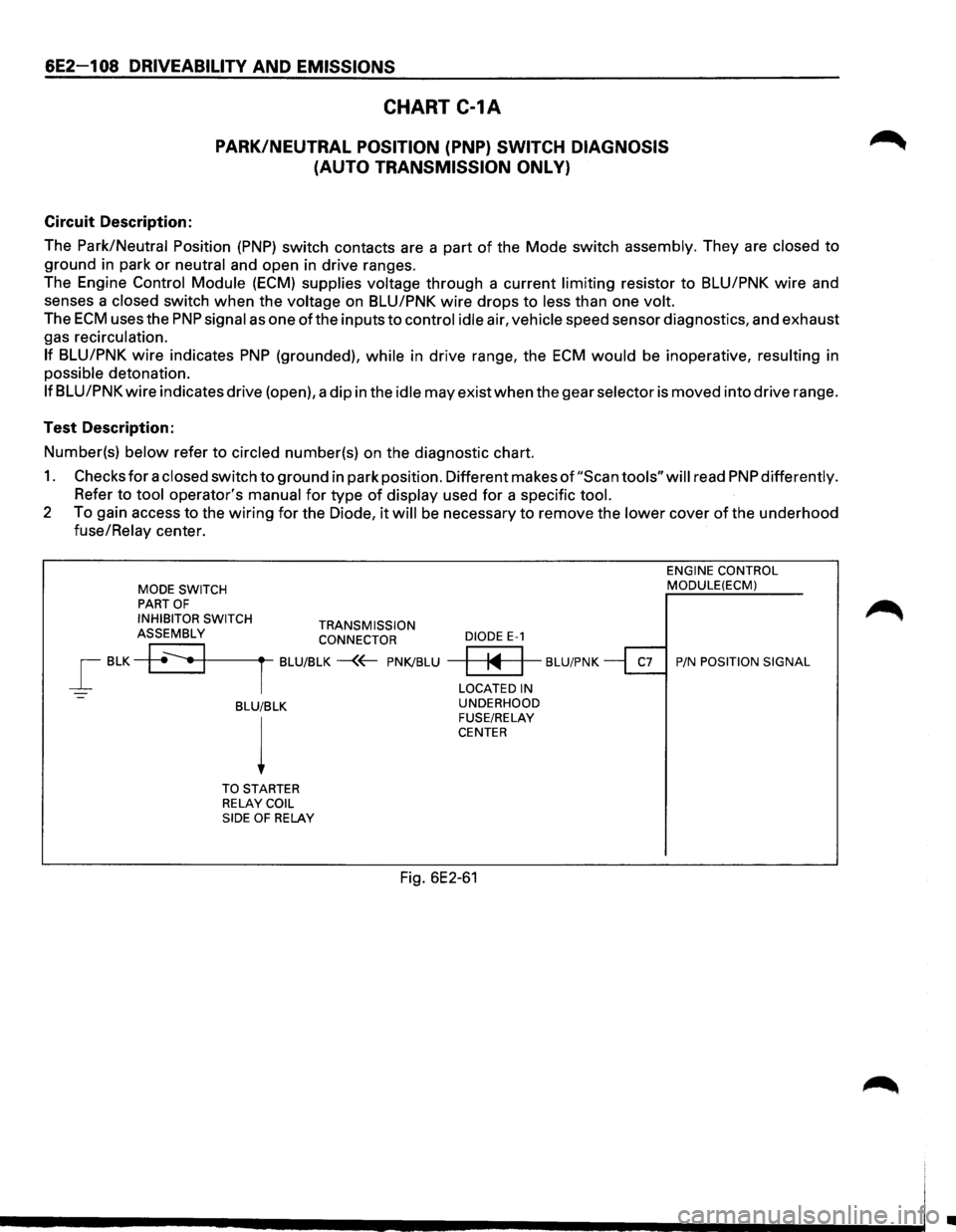
CHART C-1A
PARK/NEUTRAL POSITION (PNP} SWITCH DIAGNOSIS
(AUTO TRANSMISSION ONL
V}
Circuit Description:
The
Park/Neutral Position (PNP) switch contacts are a part of the Mode switch assembly. They are closed to
ground in park or neutral and open in drive ranges.
The Engine
Control Module (ECM) supplies voltage through a current limiting resistor to BLU/PNK wire and
senses a
closed switch when the voltage on BLU/PNK wire drops to less than one volt.
The ECM uses the PNP signal as one ofthe inputs to control idle air, vehicle speed sensor diagnostics, and exhaust
gas recirculation.
If BLU/PNK wire indicates PNP (grounded), while in drive range, the ECM would be inoperative, resulting in
possible detonation.
If BLU/PNK wire indicates drive (open), a dip in the idle may exist when the gear selector is moved into drive range.
Test Description:
Number(s)
below refer to circled number(s) on the diagnostic chart.
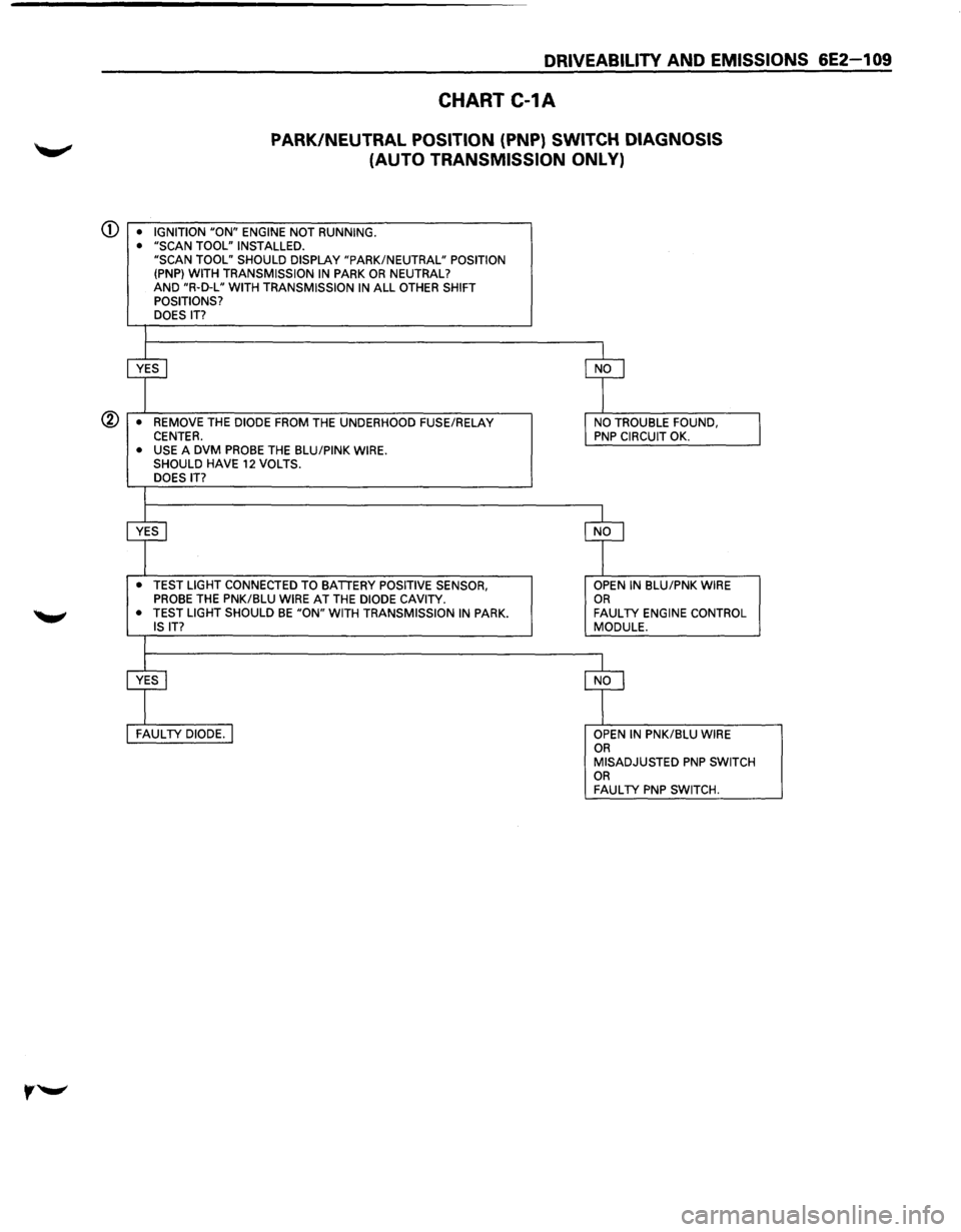
1. Checks for a closed switch to ground in park position. Different makes of "Scan tools" will read PNP differently.
Refer to tool operator's manual for type of display used for a specific tool.
2 To gain access to the wiring for the Diode, it will be necessary to remove the lower cover of the underhood
fuse/Relay center.
MODE SWITCH PART OF
INHIBITOR SWITCH TRANSMISSION ASSEMBLY CONNECTOR
_[ BLK +~•+1-------rt--BLU/BLK -{~ PNK/BLU
-BLU/BLK
l
TO STARTER
RELAY COIL
SIDE OF RELAY
DIODE E-1
ENGINE CONTROL MODULE(ECM)
~ BLU/PNK ~ P/N POSITION SIGNAL
LOCATED IN
UNDERHOOD
FUSE/RELAY
CENTER
Fig. 6E2-61
Ill
Page 805 of 1928
DRIVEABILITY AND EMISSIONS 6E2-1 09
CHART C-1A
PARK/NEUTRAL POSITION (PNP) SWITCH DIAGNOSIS
(AUTO TRANSMISSION ONLY)
CD • IGNITION "ON" ENGINE NOT RUNNING.
• "SCAN TOOL" INSTALLED.
"SCAN TOOL" SHOULD DISPLAY "PARK/NEUTRAL" POSITION
(PNP} WITH TRANSMISSION
IN PARK OR NEUTRAL?
AND "R·D-L" WITH TRANSMISSION IN ALL OTHER SHIFT
POSITIONS?
DOES
IT?
@ • REMOVE THE DIODE FROM THE UNDERHOOD FUSE/RELAY CENTER. • USE A DVM PROBE THE BLU/PINK WIRE.
SHOULD HAVE 12 VOLTS.
DOES IT?
• TEST LIGHT CONNECTED TO BATTERY POSITIVE SENSOR,
PROBE THE PNK/BLU WIRE AT THE DIODE CAVITY.
• TEST LIGHT SHOULD BE "ON" WITH TRANSMISSION IN PARK.
IS IT?
OPEN IN BLU/PNK WIRE OR FAULTY ENGINE CONTROL
MODULE.
OPEN
IN PNK/BLU WIRE OR MISADJUSTED PNP SWITCH OR FAULTY PNP SWITCH.
Page 808 of 1928
6E2-112 DRIVEABILITY AND EMISSIONS
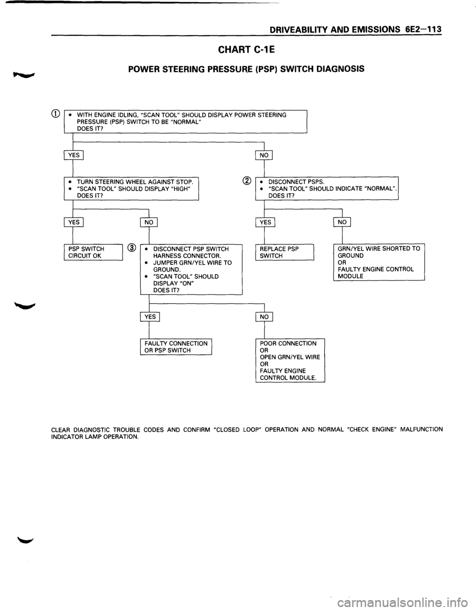
CHART C-1E
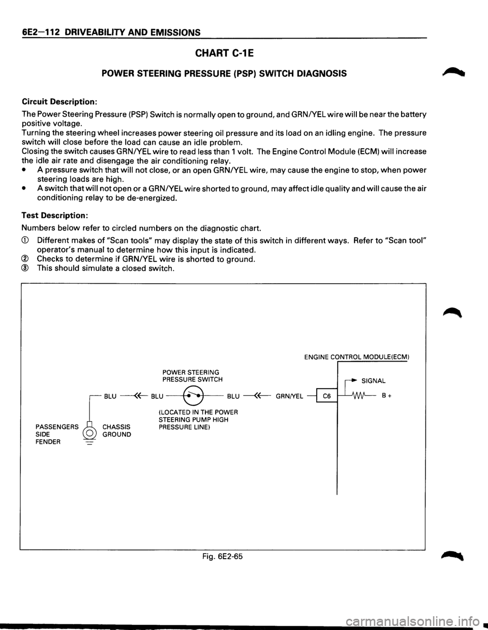
POWER STEERING PRESSURE (PSP) SWITCH DIAGNOSIS
Circuit Description:
The Power Steering Pressure
(PSP) Switch is normally open to ground, and GRNIYEL wire will be near the battery
positive
voltage.
Turning the steering wheel increases power steering oil pressure and its load on an idling engine. The pressure
switch
will close before the load can cause an idle problem.
Closing
the switch causes GRN/YEL wire to read less than 1 volt. The Engine Control Module (ECM) will increase
the
idle air rate and disengage the air conditioning relay.
•
A pressure switch that will not close, or an open GRNIYEL wire, may cause the engine to stop, when power
steering loads are high.
• A switch that will not open or a GRNIYEL wire shorted to ground, may affect idle quality and will cause the air
conditioning
relay to be de-energized.
Test Description:
Numbers
below refer to circled numbers on the diagnostic chart.
CD Different makes of "Scan tools" may display the state of this switch in different ways. Refer to "Scan tool"
operator's manual to determine how this input is indicated.
® Checks to determine if GRNIYEL wire is shorted to ground.
@ This should simulate a closed switch.
POWER STEERING PRESSURE SWITCH ENGINE
CONTROL
MODULE(ECM)
I SIGNAL
r
BLU ---(~ BLU --+8 .. •f---BLU --{~ GRN/YEL ~ ~ B +
(LOCATED IN THE POWER
STEERING PUMP HIGH PASSENGERS CHASSIS PRESSURE LINE)
SIDE GROUND
FENDER
Fig. 6E2-65
•
Page 809 of 1928
DRIVEABILITY AND EMISSIONS 6E2-113
CHART C-1E
POWER STEERING PRESSUR,.E (PSP) SWITCH DIAGNOSIS
CD • WITH ENGINE IDLING, "SCAN TOOL" SHOULD DISPLAY POWER STEERING PRESSURE (PSP) SWITCH TO BE "NORMAL" DOES IT?
•
TURN STEERING WHEEL AGAINST STOP. ® • DISCONNECT PSPS. • "SCAN TOOL" SHOULD DISPLAY "HIGH"
DOES IT? • "SCAN TOOL" SHOULD INDICATE "NORMAL".
@ • DISCONNECT PSP SWITCH HARNESS CONNECTOR.
• JUMPER GRNIYEL WIRE TO GROUND. • "SCAN TOOL" SHOULD DISPLAY "ON" DOES IT? DOES
IT?
POOR CONNECTION OR OPEN GRN/YEL WIRE OR FAULTY ENGINE
CONTROL MODULE. GRN/YEL
WIRE SHORTED TO GROUND OR FAULTY ENGINE
CONTROL MODULE
CLEAR
DIAGNOSTIC TROUBLE CODES AND CONFIRM "CLOSED LOOP" OPERATION AND NORMAL "CHECK ENGINE" MALFUNCTION
INDICATOR LAMP OPERATION.
Page 817 of 1928
Throttle Position (TP) Sensor
The Throttle Position (TP) Sensor is mounted on the
side
of the throttle body opposite the throttle lever
assembly.
Its function is to sense the current throttle
body position and relay that information to the ECM.
Knowledge ofTP is needed by the ECM to generate the
proper injector pulse width.
If the TP sensor senses a
Wide
Open Throttle, a voltage signal indicating this
condition is transmitted to the
ECM. The ECM will
widen the injector pulse, or increase the repetition rate,
permitting increased fuel
flow to each for the six fuel
injectors located in the fuel fail. As the throttle shaft
rotates in response to
movement of the accelerator
pedal (opening
or closing of the throttle body), the
throttle shaft transmits throttle
movement to the TP
sensor. A potentiometer (variable resistor) within the
TP sensor assembly creates a voltage that varies in
response to
TP. By applying a reference voltage (+5
VDC) to the TP sensor input, a varying voltage
(reflecting
TP) is available at the TP sensor output. The
voltage
output from the TP sensor is sent to the ECM
for use in determining current TP.
For further information ofTP sensor, refer to "ECM and
Sensors", Section
"6E2-C1 ". The TP sensor is an auto
zeroing type and cannot
be adjusted.
DRIVEABILITY AND EMISSIONS 6E2-121
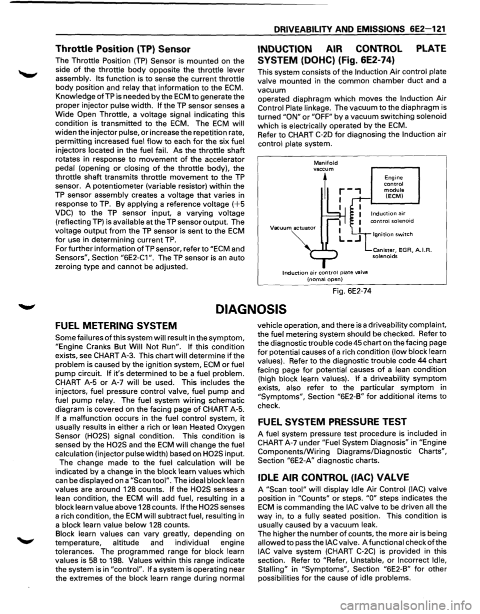
INDUCTION AIR CONTROL PLATE
SYSTEM (DOHC) (Fig. 6E2-74)
This system consists of the Induction Air control plate
valve mounted in the common chamber
duct and a
vacuum operated diaphragm
which moves the Induction Air
Control Plate linkage. The vacuum to the diaphragm is
turned
"ON" or "OFF" by a vacuum switching solenoid
which is electrically operated by the
ECM.
Refer to CHART C-20 for diagnosing the Induction air
control plate system.
Manifold vaccum
1
Vacuum actuator
Induction air control plate valve
(noma! open)
Fig. 6E2-74
Engine control module (ECM)
Ignition switch
Canister, EGR, A.I.R. solenoids
DIAGNOSIS
FUEL METERING SYSTEM
Some failures of this system will result in the symptom,
"Engine Cranks But Will Not Run". If this condition
exists, see CHART A-3. This chart will determine
if the
problem is caused by the ignition system,
ECM or fuel
pump circuit.
If it's determined to be a fuel problem.
CHART A-5
or A-7 will be used. This includes the
injectors, fuel pressure control valve, fuel
pump and
fuel pump relay. The fuel system
wiring schematic
diagram is covered on the facing page
of CHART A-5.
If a malfunction occurs in the fuel control system, it
usually results in either a rich or lean Heated Oxygen
Sensor (H02S) signal condition. This condition is
sensed by the
H02S and the ECM will change the fuel
calculation (injector pulse width) based on
H02S input.
The change made to the fuel calculation will be
indicated
by a change in the block learn values which
can be displayed on a
"Scan tool". The ideal block learn
values are around 128 counts.
If the H02S senses a
lean condition, the
ECM will add fuel, resulting in a
block learn value above 128 counts.
If the H02S senses
a rich condition, the
ECM will subtract fuel, resulting in
a block learn value below 128 counts.
Block learn values can vary greatly, depending on
temperature, altitude and individual engine
tolerances. The programmed range for block learn
values is
58 to 198. Values within this range indicate
the system is in
"control". If a system is operating near
the extremes
of the block learn range during normal vehicle
operation, and there is a driveability complaint,
the fuel metering system should be checked. Refer to
the diagnostic trouble code
45 chart on the facing page
for potential causes of a rich condition (low block learn
values). Refer to the diagnostic trouble code 44 chart
facing page
for potential causes of a lean condition
(high block learn values).
If a driveability symptom
exists, also refer to the particular symptom in
"Symptoms", Section "6E2-B" for additional items to
check.
FUEL SYSTEM PRESSURE TEST
A fuel system pressure test procedure is included in
CHART A-7 under
"Fuel System Diagnosis" in "Engine
Components/Wiring Diagrams/Diagnostic
Charts",
Section "6E2-A" diagnostic charts.
IDLE AIR CONTROL (lAC) VALVE
A "Scan tool" will display Idle Air Control (lAC) valve
position in
"Counts" or steps. "0" steps indicates the
ECM is commanding the lAC valve to be driven all the
way in, to a fully seated position. This condition is
usually caused by a vacuum leak.
The higher the number
of counts, the more air is being
allowed to pass the
lAC valve. A functional check of the
lAC valve system (CHART C-2C) is provided in this
section. Refer to
"Refer, Unstable, or Incorrect Idle,
Stalling"
in "Symptoms", Section "6E2-B" for other
possibilities
for the cause of idle problems.