lock ISUZU TROOPER 1995 User Guide
[x] Cancel search | Manufacturer: ISUZU, Model Year: 1995, Model line: TROOPER, Model: ISUZU TROOPER 1995Pages: 1928
Page 24 of 1928
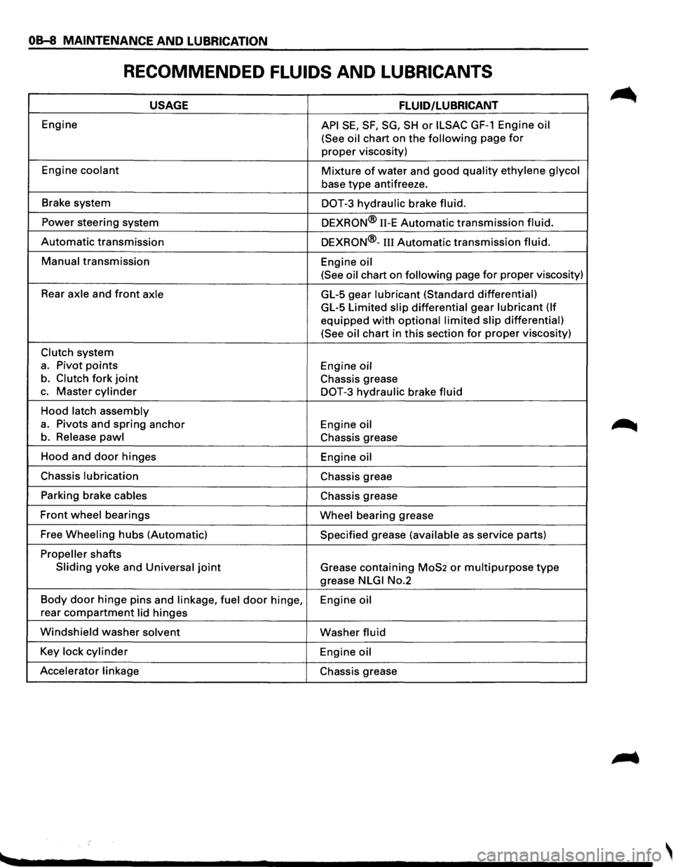
OB-8 MAINTENANCE AND LUBRICATION
RECOMMENDED FLUIDS AND LUBRICANTS
USAGE FLUID/LUBRICANT
Engine API SE, SF, SG, SH or ILSAC GF-1 Engine oil
(See oil
chart on the following page for
proper viscosity)
Engine
coolant Mixture of water and good quality ethylene glycol
base type antifreeze.
Brake system
DOT-3 hydraulic brake fluid.
Power steering system
DEXRON® 11-E Automatic transmission fluid.
Automatic transmission DEXRON®-III Automatic transmission fluid.
Manual transmission
Engine oil
(See oil
chart on following page for proper viscosity)
Rear
axle and front axle GL-5 gear lubricant (Standard differential)
GL-5 Limited slip differential gear lubricant (If
equipped with optional limited slip differential)
(See oil
chart in this section for proper viscosity)
Clutch system
a. Pivot points Engine oil
b. Clutch fork joint Chassis grease
c. Master cylinder DOT-3 hydraulic brake fluid
Hood latch assembly
a. Pivots and spring anchor
Engine oil
b. Release pawl Chassis grease
Hood and
door hinges
Engine oil
Chassis lubrication Chassis greae
Parking brake
cables Chassis grease
Front wheel bearings Wheel bearing grease
Free
Wheeling hubs (Automatic) Specified grease (available as service parts)
Propeller shafts
Sliding yoke and Universal joint Grease containing MoS2 or multipurpose type
grease NLGI No.2
Body
door hinge pins and linkage, fuel door hinge,
Engine oil
rear compartment lid hinges
Windshield washer solvent Washer fluid
Key lock cylinder Engine oil
Accelerator linkage
Chassis grease
Page 27 of 1928
,
MAINTENANCE AND LUBRICATION OB-11
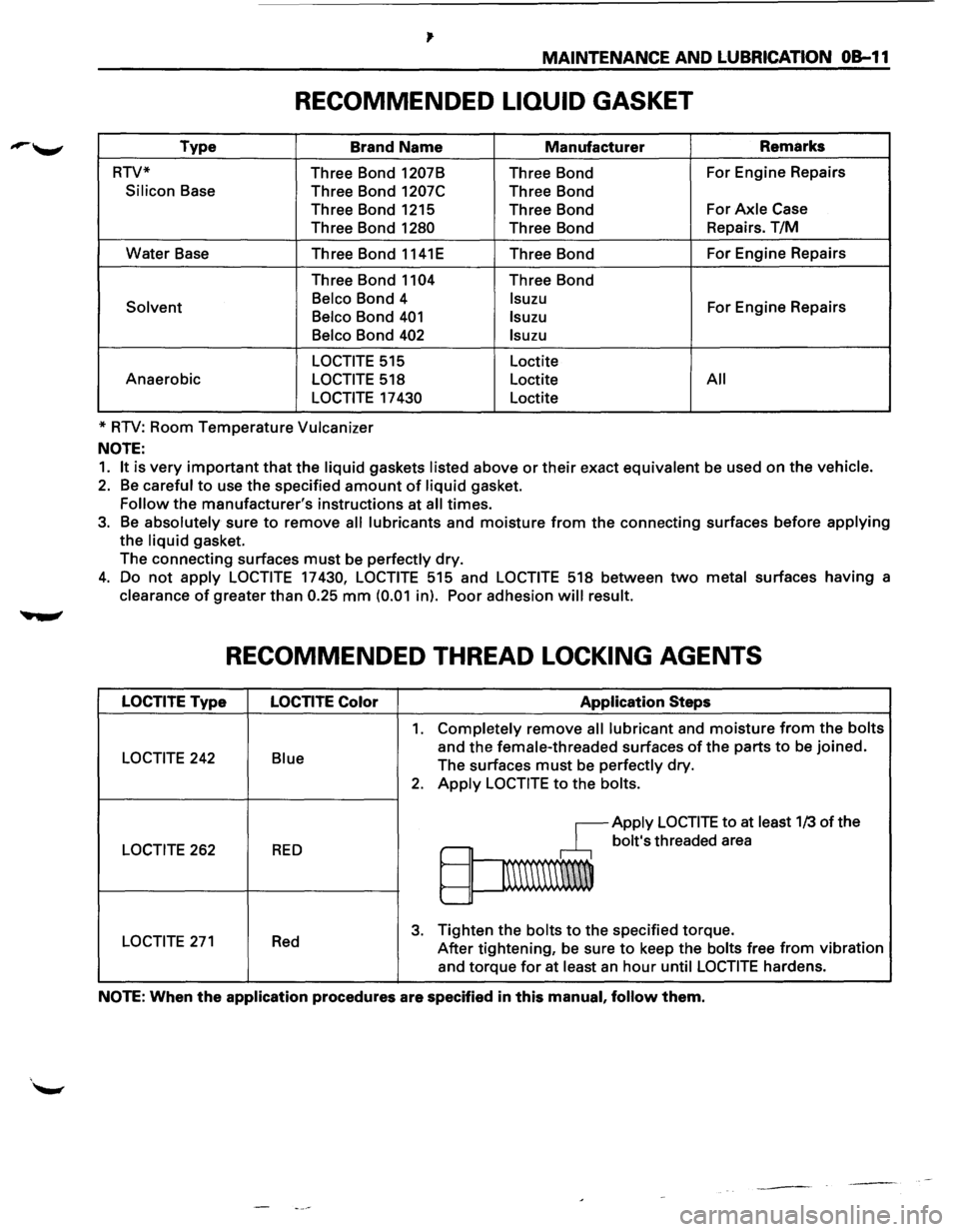
RECOMMENDED LIQUID GASKET
Type Brand Name Manufacturer Remarks
RTV* Three Bond
1207B Three Bond For
Engine Repairs
Silicon Base
Three Bond 1207C Three Bond
Three Bond 1215 Three Bond For
Axle Case
Three Bond
1280 Three Bond Repairs.
T/M
Water Base
Three Bond 1141E Three Bond For
Engine Repairs
Three Bond
1104 Three Bond
Solvent Belco Bond
4 lsuzu For Engine Repairs Belco Bond 401 lsuzu
Belco
Bond 402 lsuzu
LOCTITE
515 Loctite
Anaerobic
LOCTITE 518 Loctite All
LOCTITE
17 430 Loctite
*
RTV: Room Temperature Vulcanizer
NOTE:
1. It is very important that the liquid gaskets listed above or their exact equivalent be used on the vehicle.
2. Be careful to use the specified amount of liquid gasket.
Follow the manufacturer's instructions at all times.
3. Be absolutely sure to remove all lubricants and moisture from the connecting surfaces before applying
the liquid gasket.
The connecting surfaces
must be perfectly dry.
4. Do not apply LOCTITE 17430, LOCTITE 515 and LOCTITE 518 between two metal surfaces having a
clearance
of greater than 0.25 mm (0.01 in). Poor adhesion will result.
RECOMMENDED THREAD LOCKING AGENTS
LOCTITE Type LOCTITE Color Application Steps
1. Completely remove all lubricant and moisture from the bolts
LOCTITE 242 Blue and the female-threaded surfaces of the parts to be joined.
The surfaces
must be perfectly dry.
2. Apply LOCTITE to the bolts.
~Apply LOCTITE to at least 1/3 of the
LOCTITE 262 RED ,.-bolt's threaded area
~
1\\\\\\\W
'--
LOCTITE 271 Red 3. Tighten the bolts to the specified torque.
After tightening, be sure
to keep the bolts free from vibration
and torque
for at least an hour until LOCTITE hardens.
NOTE: When the application procedures are specified in this manual, follow them.
Page 34 of 1928
1A-4 HEATING AND VENTILATION
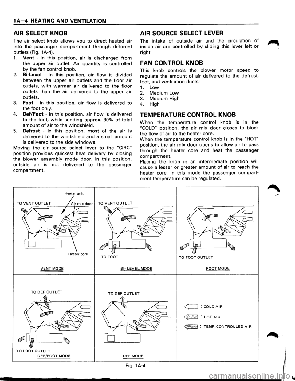
AIR SELECT KNOB
The air select knob allows you to direct heated air
into the passenger
compartment through different
outlets (Fig. 1A-4).
1. Vent -In this position, air is discharged from
the upper air
outlet. Air quantity is controlled
by the fan control knob.
2. Bi-Level -In this position, air flow is divided
between the upper air
outlets and the floor air
outlets, with warmer air delivered to the floor
outlets
than the air delivered to the upper air
outlets.
3. Foot -In this position, air flow is delivered to
the foot only.
4. Def/Foot -In this position, air flow is delivered
to the foot, while sending approx. 30% of total
amount of air to the windshield.
5. Defrost -In this position, most of the air is
delivered to the windshield and a small amount
is delivered to the side windows.
Moving the air source select lever to the "CIRC"
position provides quickest heat delivery by closing
the blower assembly mode door. In this position,
outside air
is not delivered to the passenger
compartment.
Heater unit
D
Heater core TO FOOT
AIR SOURCE SELECT LEVER
The intake of outside air and the circulation of
inside air are controlled by sliding this lever left or
right.
FAN CONTROL KNOB
This knob controls the blower motor speed to
regulate the amount of air delivered to the defrost,
foot, and
ventilation ducts:
1. Low
2. Medium Low
3. Medium High
4. High
TEMPERATURE CONTROL KNOB
When the temperature control knob is in the
"COLD" position, the air mix door closes to block
the flow of air to the heater core.
When the temperature
control knob is in the "HOT"
position, the air mix door opens to allow air to pass
through the heater core and heat the passenger
compartment.
Placing the knob in an intermediate position will
cause a lesser or greater amount of air to reach the
heater core.
In this mode the passenger compart
ment temperature can be regulated.
.r.( /
<_;~~
'--'R!I=---_____.J'
TO FOOT OUTLET
VENT MODE 81-LEVEL MODE FOOT MODE
TO FOOT OUTLET
DEF/FOOT MODE DEF MODE
Fig. 1A-4
<==:J : COLD AIR
~: HOTAIR
~ : TEMP.CONTROLLED AIR
I ........................................................................\
...... ------------------~1
Page 40 of 1928
1A-10 HEATING AND VENTILATION
~ INDIVIDUAL INSPECTION
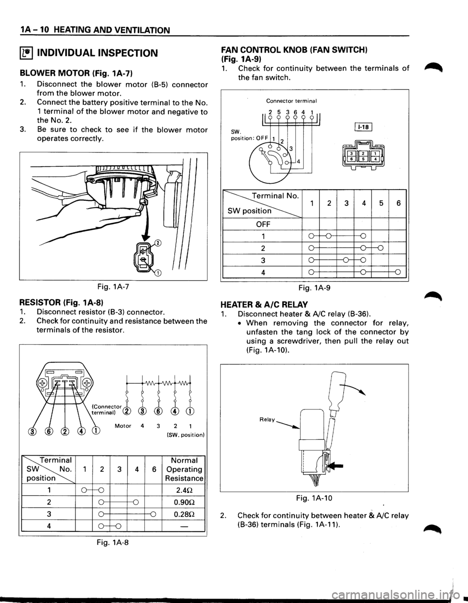
BLOWER MOTOR (Fig. 1A-7)
1. Disconnect the blower motor (B-5) connector
from the blower motor.
2. Connect the battery positive terminal to the No.
1 terminal of the blower motor and negative to
the No.2.
3. Be sure to check to see if the blower motor
operates correctly.
Fig. 1A-7
RESISTOR (Fig. 1A-8)
1. Disconnect resistor (B-3) connector.
2. Check for continuity and resistance between the
terminals of the resistor.
Motor 4 3 2
(SW. position)
Terminal Normal
SW No.
2 3 4 6 Operating
position Resistance
1 2.4Q
2 0.90Q
3 0.28Q
4
Fig. 1A-8
FAN CONTROL KNOB (FAN SWITCH)
(Fig. 1A-9)
1. Check for continuity between the terminals of
the fan switch.
Connector terminal
2 3 4 5 6
OFF
1
2
3
4
Fig. 1A-9
HEATER & A/C RELAY
1. Disconnect heater & A!C relay (B-36).
• When removing the connector for relay,
unfasten the tang lock of the connector by
using a screwdriver, then pull the relay out
(Fig. 1A-10).
Fig. 1A-10
2. Check for continuity between heater & A!C relay
(B-36) terminals (Fig. 1A-11).
~
•
Page 53 of 1928
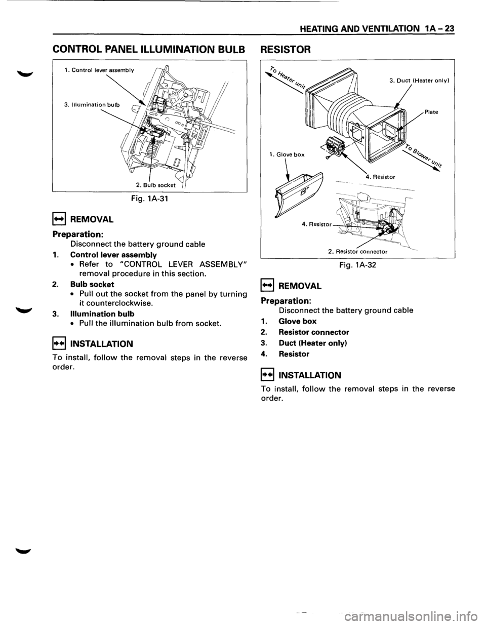
CONTROL PANEL ILLUMINATION BULB
1••1 REMOVAL
Preparation:
Fig. 1A-31
Disconnect
the battery ground cable
1. Control lever assembly
• Refer to "CONTROL LEVER ASSEMBLY"
removal
procedure in this section.
2. Bulb socket
• Pull out the socket from the panel by turning
it counterclockwise.
3.
Illumination bulb
• Pull the illumination bulb from socket.
I••IINSTALLATION
To install, follow the removal steps in the reverse
order.
HEATING AND VENTILATION 1A-23
RESISTOR
1. Glove box
1••1 REMOVAL
Preparation:
3. Duct (Heater only)
Plate
2. Resistor connector
Fig. 1A-32
Disconnect the battery
ground cable
1. Glove box
2. Resistor connector
3. Duct (Heater only)
4. Resistor
I••IINSTALLATION
To install, follow the removal steps in the reverse
order.
Page 58 of 1928
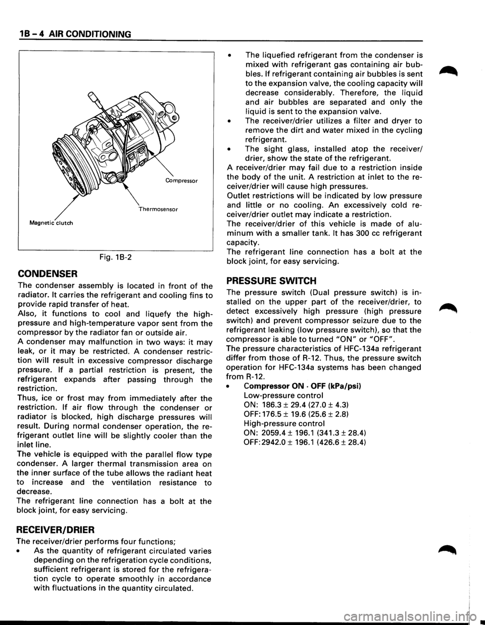
1 B - 4 AIR CONDITIONING
Compressor
Thermosensor
Magnetic clutch
Fig. 18-2
CONDENSER
The condenser assembly is located in front of the
radiator. It carries the refrigerant and cooling fins to
provide rapid transfer of heat.
Also, it functions to cool and liquefy the high
pressure and high-temperature vapor sent from the
compressor by the radiator fan or outside air.
A condenser
may malfunction in two ways: it may
leak, or it may be restricted. A condenser restric
tion will result in excessive compressor discharge
pressure.
If a partial restriction is present, the
refrigerant expands after passing through the
restriction.
Thus, ice
or frost may from immediately after the
restriction. If air flow through the condenser or
radiator is blocked, high discharge pressures will
result. During normal condenser operation, the re
frigerant outlet line will be slightly cooler than the
inlet line.
The vehicle is equipped with the parallel flow type
condenser. A larger thermal transmission area on
the inner surface of the tube allows the radiant heat
to increase and the ventilation resistance to
decrease.
The
refrigerant line connection has a bolt at the
block joint, for easy servicing.
RECEIVER/DRIER
The receiver/drier performs four functions;
• As the quantity of refrigerant circulated varies
depending on the refrigeration cycle conditions,
sufficient refrigerant is stored for the refrigera
tion cycle to operate smoothly in accordance
with fluctuations in the quantity circulated. •
The liquefied refrigerant from the condenser
is
mixed with refrigerant gas containing air bub
bles. If refrigerant containing air bubbles is sent
to the expansion valve, the cooling capacity will
decrease considerably. Therefore, the liquid
and air bubbles are separated and only the
liquid is sent to the expansion valve.
•
The receiver/drier utilizes a filter and dryer to
remove the dirt and water mixed in the cycling
refrigerant.
• The sight glass, installed atop the receiver/
drier, show the state of the refrigerant.
A receiver/drier may fail due to a restriction inside
the body of the unit. A restriction at inlet to the re
ceiver/drier
will cause high pressures.
Outlet restrictions will be indicated by low pressure
and
little or no cooling. An excessively cold re
ceiver/drier
outlet may indicate a restriction.
The receiver/drier
of this vehicle is made of alu
minum with a smaller tank. It has 300 cc refrigerant
capacity.
The
refrigerant line connection has a bolt at the
block joint, for easy servicing.
PRESSURE SWITCH
The pressure switch (Dual pressure switch) is in
stalled on the upper part of the receiver/drier, to
detect excessively high pressure (high pressure
switch) and prevent compressor seizure due to the
refrigerant leaking (low pressure switch), so that the
compressor is able to turned "ON" or "OFF".
The pressure characteristics of HFC-134a refrigerant
differ from those of R-12. Thus, the pressure switch
operation for HFC-134a systems has been changed
from R-12.
• Compressor ON · OFF (kPa/psi)
Low-pressure control
ON: 186.3 ± 29.4 (27.0 ± 4.3)
OFF: 176.5 ± 19.6 (25.6 ± 2.8)
High-pressure
control
ON: 2059.4 ± 196.1 (341.3 ± 28.4)
OFF: 2942.0 ± 196.1 (426.6 ± 28.4)
Page 66 of 1928
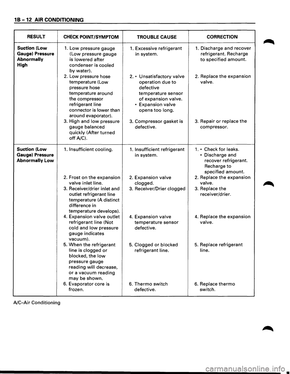
1 B -12 AIR CONDITIONING
RESULT CHECK POINT /SYMPTOM
TROUBLE CAUSE CORRECTION
Suction (low 1. Low pressure
gauge 1. Excessive refrigerant 1. Discharge and recover
Gauge) Pressure (Low pressure gauge
in system. refrigerant.
Recharge
Abnormally is lowered after to specified amount.
High condenser is cooled
by water).
2. Low pressure hose 2. • Unsatisfactory valve 2. Replace the expansion
temperature (Low operation due to valve.
pressure hose
defective
temperature around
temperature sensor
the compressor of expansion valve.
refrigerant line
• Expansion valve
connector is lower than opens too long.
around evaporator).
3. High and low pressure 3. Compressor gasket is 3. Repair or replace the
gauge balanced defective. compressor.
quickly (After turned
off A/C).
Suction (low 1. Insufficient cooling. 1. Insufficient refrigerant 1 .• Check for leaks.
Gauge) Pressure in system. • Discharge and
Abnormally Low recover refrigerant.
Recharge
to
specified amount.
2. Frost on the expansion 2. Expansion valve 2. Replace the expansion
valve inlet line.
clogged. valve.
3. Receiver/drier inlet and 3. Receiver/Drier clogged 3. Replace the
outlet refrigerant line receiver/drier.
temperature (A distinct
difference in
temperature
develops).
4. Expansion valve outlet 4. Expansion valve 4. Replace the expansion
refrigerant line (Not temperature sensor valve.
cold
and low pressure defective.
gauge indicates
vacuum).
5. When the refrigerant 5. Clogged or blocked 5. Replace refrigerant
line is clogged or refrigerant line. line.
blocked,
the low
pressure gauge
reading
will decrease,
or a vacuum reading
may be shown.
6. Evaporator core is 6. Thermo switch 6. Replace thermo
frozen.
defective. switch.
A/C-Air Conditioning
..
Page 73 of 1928
AIR CONDITIONING 1 B -19
ON-VEHICLE SERVICE
GENERAL REPAIR PROCEDURE
Precautions for Replacement or Repair of Air
Conditioning Parts
There are certain procedures, practices and pre
cautions
that should be followed when servicing air
conditioning systems:
• Keep your work area clean.
•
Always wear safety goggle and protective gloves
when working on refrigerant systems.
• Beware of the danger of carbon monoxide fumes
caused by running the engine.
• Beware of discharged refrigerant in enclosed or
improperly ventilated garages.
• Always disconnect the negative battery cable and
discharge and recover the refrigerant
whenever
repairing the air conditioning system.
• When discharging and recovering the refrigerant,
do not allow refrigerant to discharge too fast; it
will draw compressor oil out of the system.
• Keep moisture and contaminants out of the sys
tem.
When disconnecting or removing any lines
or parts, use plugs or caps to close the fittings
immediately.
Never remove the caps or plugs until the lines or
parts are reconnected or installed.
•
When disconnecting or reconnecting the lines,
use
two wrenches to support the line fitting, to
prevent from twisting or other damage.
• Always install new 0-rings whenever a connec
tion is disassembled.
• Before connecting any hoses or lines, apply new
specified compressor oil to the 0-rings.
• When removing and replacing any parts which
require discharging the refrigerant circuit, the
operations described in
this section must be per
formed in the following sequence:
1. Use the J-39500 (ACR4
: HFC-134a Refrigerant
Recovery/Recycling/Recharging/System)
or
equivalent to thoroughly discharge and re
cover
the refrigerant.
2. Remove and replace the defective part.
3.
After evacuation, charge the air conditioning
system and check for leaks.
Repair of Refrigerant Leaks
Refrigerant Line Connections
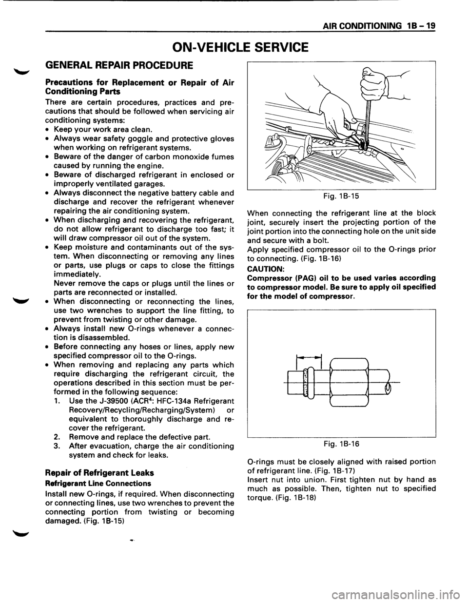
Install new 0-rings, if required. When disconnecting
or connecting lines, use two wrenches to prevent the
connecting
portion from twisting or becoming
damaged. (Fig. 1 B-15) Fig.
18-15
When connecting the refrigerant
line at the block
joint, securely insert the projecting portion of the
joint portion into the connecting hole on the unit side
and secure
with a bolt.
Apply specified compressor oil to the 0-rings prior
to connecting. (Fig. 18-16)
CAUTION:
Compressor (PAGI oil to be used varies according
to compressor model. Be sure to apply oil specified
for the model of compressor.
~1;1_ ~ ' .. J '--......
Fig. 18-16
0-rings must be closely aligned with raised portion
of refrigerant line. (Fig. 18-17)
Insert nut into union. First tighten nut by hand as
much as possible. Then, tighten nut to specified
torque. (Fig. 1 8-18)
Page 85 of 1928
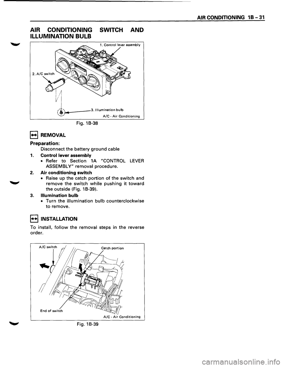
AIR CONDITIONING SWITCH AND
ILLUMINATION BULB
i-..---3. Illumination bulb
1++1 REMOVAL
Preparation:
Fig. 18-38
A/C -Air Conditioning
Disconnect the battery ground cable
1. Control lever assembly
• Refer to Section 1A "CONTROL LEVER
ASSEMBLY" removal procedure.
2. Air conditioning switch
• Raise up the catch portion of the switch and
remove the switch while pushing it toward
the outside (Fig. 1 B-39).
3. Illumination bulb
• Turn the illumination bulb counterclockwise
to remove.
I••IINSTALLATION
To install, follow the removal steps in the reverse
order.
End of switch
Fig. 18-39
AIR CONDITIONING 1 B -31
Page 89 of 1928
COMPRESSOR OVERHAUL 1 D - 1
SECTION 10
COMPRESSOR OVERHAUL
CONTENTS
General Description . . . . . . . . . . . . . . . . . . . . . 1 D-1
Diagnosis . . . . . . . . . . . . . . . . . . . . . . . . . . . . . 1
D-2
General Information . . . . . . . . . . . . . . . . . . . . 1 D-3
Compressor Oil . . . . . . . . . . . . . . . . . . . . . . 1 D-3
Service Procedures . . . . . . . . . . . . . . . . . . . . . 1D-5
Magnetic Clutch Assembly . . . . . . . . . . . . . 1 D-5
Main Data and Specifications . . . . . . . . . . . . . 1 D-8
General Specifications . . . . . . . . . . . . . . . . . 1 D-8
Torque Specifications . . . . . . . . . . . . . . . . . 1 D-8
Special Tools . . . . . . . . . . . . . . . . . . . . . . . . . . 1D-9
GENERAL DESCRIPTION
When servicing the compressor, keep dirt or foreign
material from getting on or into the compressor
parts and system. Clean tools and a clean work area
are
important for proper service. The compressor
connections and the outside of the compressor
should be cleaned before any "On-Vehicle" repair,
or before removal of the compressor. The parts must
be kept clean at all times and any parts to be
reassembled
should be cleaned with Trichloro
ethane, naphtha, kerosene, or equivalent solvent,
and
dried with dry air. Use only lint free cloths to
wipe parts.
The
operations described below are based on bench
overhaul
with compressor removed from the
vehicle, except as noted. They have been prepared
in
order of accessibility of the components. When
the compressor is removed from the vehicle for
servicing, the oil remaining in the compressor
should be discarded and new compressor oil added
to the compressor.
Magnetic clutch assembly repair procedures require
that the system be discharged of refrigerant. (Refer
to Section 1 B for "REFRIGERANT RECOVERY".)
Compressor malfunction will appear in one of four
ways: noise, seizure, leakage or low discharge
pressure. Resonant
compressor noises are not
cause for alarm; however, irregular noise or rattles
may indicate broken parts or excessive clearances
due to wear. To check seizure, de-energize the
magnetic clutch and check to see if the drive plate
can be rotated.
If rotation is impossible, the com
pressor is seized. Low discharge pressure may be
due to a faulty internal seal of the compressor, or a
restriction in the compressor.
Low discharge pres
sure
may also be due to an insufficient refrigerant
charge
or a restriction elsewhere in the system.
These possibilities
should be checked prior to
servicing the compressor. If the compressor is
inoperative,
but is not seized, check to see if current
is being supplied to the magnetic clutch coil
terminals.
This vehicle is equipped with five-vane rotary com
pressor.
The
compressor has vanes built into a rotor which is
mounted on a shaft.
When the shaft rotates, the vanes built into the
cylinder block assembly are opened by centrifugal
force.
This changes the volume of the space formed by the
rotor and cylinder, resulting in the intake and
compression of the refrigerant gas. The discharge
valve and the
valve stopper, which protects the
discharge valve, are
built into the cylinder block
assembly. There is no suction valve but a shaft seal
is
installed between the shaft and head; a trigger
valve, which applies back pressure to the vanes, is
installed in the cylinder block and a refrigerant gas
temperature sensor is installed in the front head.
The specified
quantity of compressor oil is contained
in
the compressor to lubricate the various parts
using
the refrigerant gas discharge pressure.
The thermo sensor is installed to the front head of
the compressor to protect it by stopping its
operation when the refrigerant gas is insufficient or
when the temperature get abnormally high.
•OFF ..... 160 ±soc (320.0 ± 9.0°F)
•ON ..... 135 ±soc (275.0 ± 9.0°F)
The oil used in the HFC-134a system compressor
differs from that used in R-12 systems.
Also, compressor
oil to be used varies according to
the compressor model. Be sure to avoid mixing two
or more different types of oil.
If the wrong oil is used, lubrication will be poor and
the compressor will seize or malfunction.
The specified
amount of the compressor oil is
150cc (5.0 fl.oz.).