lock ISUZU TROOPER 1995 Owner's Guide
[x] Cancel search | Manufacturer: ISUZU, Model Year: 1995, Model line: TROOPER, Model: ISUZU TROOPER 1995Pages: 1928
Page 143 of 1928
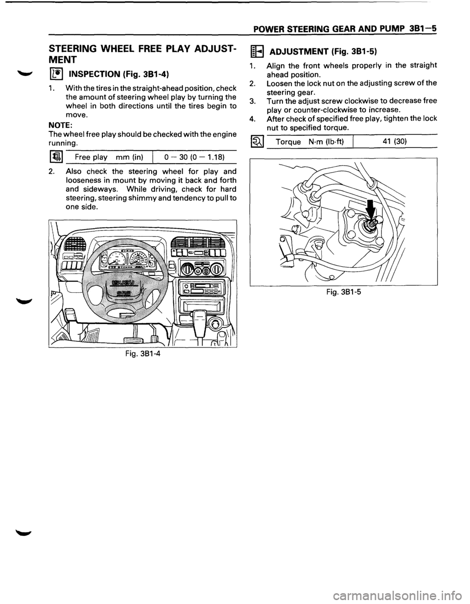
STEERING WHEEL FREE PLAY ADJUST
MENT
IL•I INSPECTION (Fig. 381-4)
1. With the tires in the straight-ahead position, check
the
amount of steering wheel play by turning the
wheel in both directions until the tires begin to
move.
NOTE:
The wheel free play should be checked with the engine
running.
~~~~F-r-ee--pl-ay---m-m--(in_)_,j--o----3-0-(0----1-.1-8~)-
2. Also check the steering wheel for play and
looseness in mount by moving it back and forth
and sideways.
While driving, check for hard
steering, steering
shimmy and tendency to pull to
one side.
POWER STEERING GEAR AND PUMP 381-5
IEEI ADJUSTMENT (Fig. 381-5)
1. Align the front wheels properly in the straight
ahead position.
2. Loosen the lock nut on the adjusting screw of the
steering gear.
3. Turn the adjust screw clockwise to decrease free
play or counter-clockwise to incre~se.
4. After check of specified free play, t1ghten the lock
nut to specified torque.
~~~ Torque N·m (lb·ft) I 41 (30)
Fig. 381-5
Page 147 of 1928
POWER STEERING GEAR AND PUMP 381-9
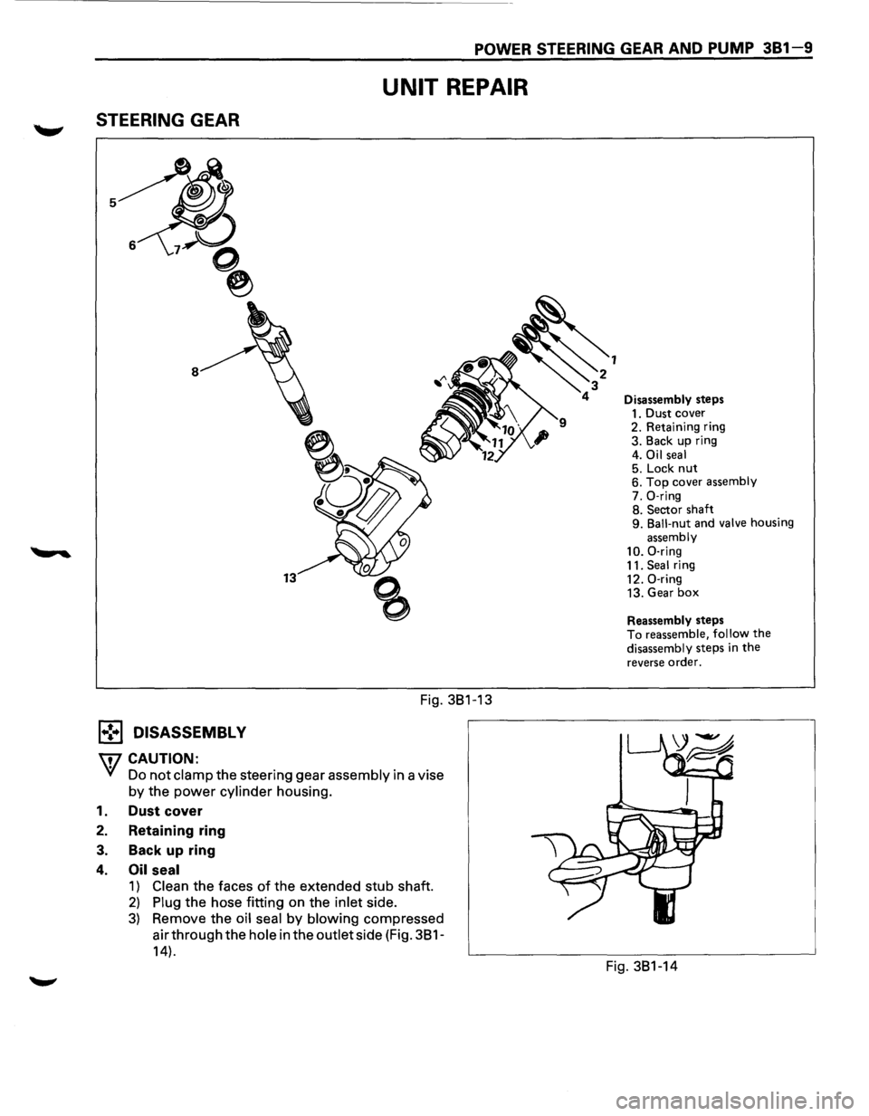
STEERING GEAR
1.,!,.1 DISASSEMBL V
W CAUTION:
UNIT REPAIR
Fig. 381-13
Yf Do not clamp the steering gear assembly in a vise
by the power cylinder housing.
1. Dust cover
2. Retaining ring
3. Back up ring
4. Oil seal
1) Clean the faces of the extended stub shaft.
2) Plug the hose fitting on the inlet side.
3) Remove the oil seal by blowing compressed
air through the
hole in the outlet side (Fig. 381-
14).
Disassembly steps
1. Dust cover
2. Retaining ring
3. Back up ring
4.
Oil seal 5. Lock nut 6. Top cover assembly
7. 0-ring
8. Sector shaft
9.
Ball-nut and valve housing
assembly
10. 0-ring
11. Seal ring
12. 0-ring
13. Gear
box
Reassembly steps
To reassemble, follow the
disassembly steps in the
reverse order.
Fig. 381-14
Page 148 of 1928
381-10 POWER STEERING GEAR AND PUMP
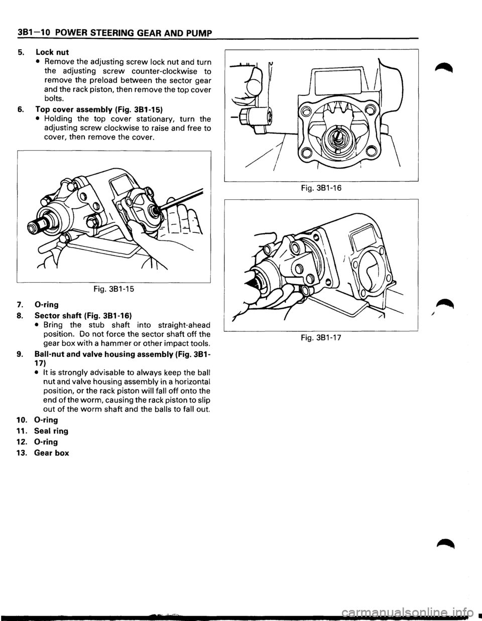
5. Lock nut
• Remove the adjusting screw lock nut and turn
the adjusting
screw counter-clockwise to
remove the preload between the sector gear
and the rack piston, then remove the
top cover
bolts.
6. Top cover assembly (Fig. 381-15)
• Holding the top cover stationary, turn the
adjusting screw
clockwise to raise and free to
cover, then remove the cover.
Fig. 381-15
7. 0-ring
8. Sector shaft (Fig. 381-16)
• Bring the stub shaft into straight-ahead
position. Do not force the sector shaft
off the
gear
box with a hammer or other impact tools.
9. Ball-nut and valve housing assembly (Fig. 381-
17)
• It is strongly advisable to always keep the ball
nut and valve housing assembly in a horizontal
position, or the rack piston will fall off onto the
end
of the worm, causing the rack piston to slip
out of the worm shaft and the balls to fall out.
10. 0-ring
11. Seal ring
12.
0-ring
13. Gear box
Fig. 381-16
Fig. 381-17
•
Page 150 of 1928
381 -12 POWER STEERING GEAR AND PUMP
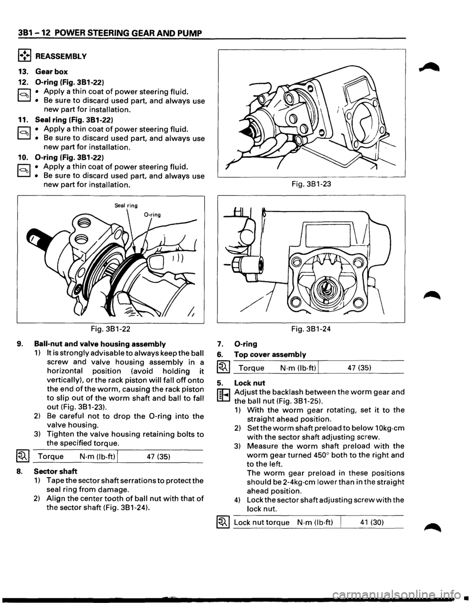
l•!+l REASSEMBLY
13. Gear box
12.
0-ring (fig. 381-22)
r:::;:, • Apply a thin coat of power steering fluid.
D • Be sure to discard used part, and always use
new part for installation.
11. Seal ring (fig. 381-22)
r:::;:, • Apply a thin coat of power steering fluid.
D • Be sure to discard used part, and always use
new part for installation.
10.
0-ring (fig. 381-22)
r:::;:, • Apply a thin coat of power steering fluid.
D • Be sure to discard used part, and always use
new part for installation.
Seal ring
Fig. 3B1-22
9.
Ball-nut and valve housing assembly
1) It is strongly advisable to always keep the ball
screw and valve housing assembly in a
horizontal position (avoid holding it
vertically), or the rack piston will fall off onto
the end of the worm, causing the rack piston
to slip out of the worm shaft and ball to fall
out (Fig. 3B1-23).
2) Be careful not to drop the 0-ring into the
valve housing.
3) Tighten the valve housing retaining bolts to
the specified torque.
~~~ Torque N·m (lb.ft) I 47 (35)
8. Sector shaft
1) Tape the sector shaft serrations to protect the
seal ring from damage.
2) Align the center tooth of ball nut with that of
the sector shaft (Fig. 3B1-24). Fig.
3B1-23
Fig. 3B1-24
7. 0-ring
6. Top cover assembly
~~~ Torque N-m (lb·ftl I 47 (35)
5. Lock nut
r:cJ Adjust the backlash between the worm gear and
L:D the ball nut (Fig. 3B1-25).
1) With the worm gear rotating, set it to the
straight ahead position.
2) Set the worm shaft preload to below 1 Okg-cm
with the sector shaft adjusting screw.
3) Measure the worm shaft preload with the
worm gear turned 450° both to the right and
to the left.
The worm gear preload in these positions
should be 2-4kg-cm lower than in the straight
ahead position.
4) Lock the sector shaft adjusting screw with the
lock nut.
~~~ Lock nut torque N-m (lb·ft) I 41 (30)
•
Page 157 of 1928
STEERING LINKAGE 383-1
SECTION 383
STEERING LINKAGE
w CAUTION:
• When fasteners are removed, always reinstall them at the same location from which they were removed. If a
fastener needs
to be replaced, use the correct part number fastener for that application. If the correct part
number fastener is not available, a fastener of equal size and strength (or stronger) may be used. Fasteners
that are not reused, and those requiring thread locking compound, will be called out. The correct torque
value must be used when installing fasteners that require it. If the above conditions are not followed, parts or
system damage could result.
CONTENTS
General Description . . . . . . . . . . . . . . . . . . . . 383-1
On-Vehicle Service .................... 383-2
Center Track Rod Assembly . . . . . . . . . . . 383-2
Outer Track Rod Assembly . . . . . . . . . . . . 383-4
Relay Lever . . . . . . . . . . . . . . . . . . . . . . . . . 383-6 Main
Data
and Specifications ............ 383-8
Torque Specifications
................ 383-8
Special Tools .......................... 383-8
GENERAL DESCRIPTION
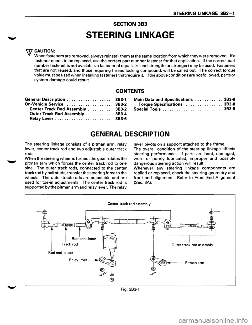
The steering linkage consists of a pitman arm, relay
lever,
center track rod and two adjustable outer track
rods.
When the steering
wheel is turned, the gear rotates the
pitman arm
which forces the center track rod to one
side. The outer track rods, connected to the center
track rod
by ball studs, transfer the steering force to the
wheels. The outer track rods are adjustable and are
used
for toe-in adjustments. The center track rod is
supported
by the pitman arm and relay lever. The relay lever
pivots
on a support attached to the frame.
The
overall condition of the steering linkage affects
steering performance.
If parts are bent, damaged,
worn or poorly lubricated, improper and possibly
dangerous steering action will result.
Whenever any steering linkage components are
replied or replaced, check the steering geometry and
front end alignment. Refer to Front End Alignment
(Sec. 3A).
Center track rod assembly
Rod end, inner
Track rod
Rod end, outer
Relay lever---~·--:;:::jo
I
I Outer track rod assembly
Fig. 383-1
Page 160 of 1928
383 - 4 STEERING LINKAGE
OUTER TRACK ROD ASSEMBLY
1+•1 REMOVAL
Fig. 3B3-6
2.
Preparation: • Remove wheel and tire assembly.
Refer to "Wheels and tires" in
section
3E. ~
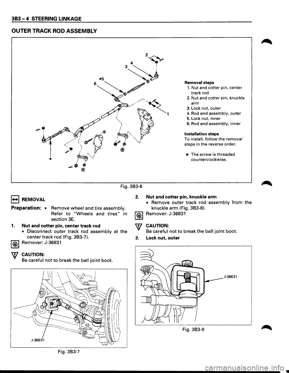
Removal steps
1. Nut and cotter pin, center
track rod
2. Nut and cotter pin, knuckle
arm
3. Lock nut, outer
4. Rod end assembly, outer
5. Lock nut, inner
6. Rod end assembly, inner
Installation steps
To install, follow the removal
steps in the reverse order.
* The screw is threaded
counterclockwise.
Nut and cotter pin, knuckle arm
• Remove outer track rod assembly from the
knuckle arm (Fig. 3B3-8).
Remover: J-36831
1. Nut and cotter pin, center track rod
• Disconnect outer track rod assembly at the
center track rod (Fig. 3B3-7).
'\f CAUTION:
Be careful not to break the ball joint boot.
3. Lock nut, outer Remover: J-36831
CAUTION:
Be careful not to break the ball joint boot.
J-36831
Fig. 3B3-8
Fig. 3B3-7
Page 161 of 1928
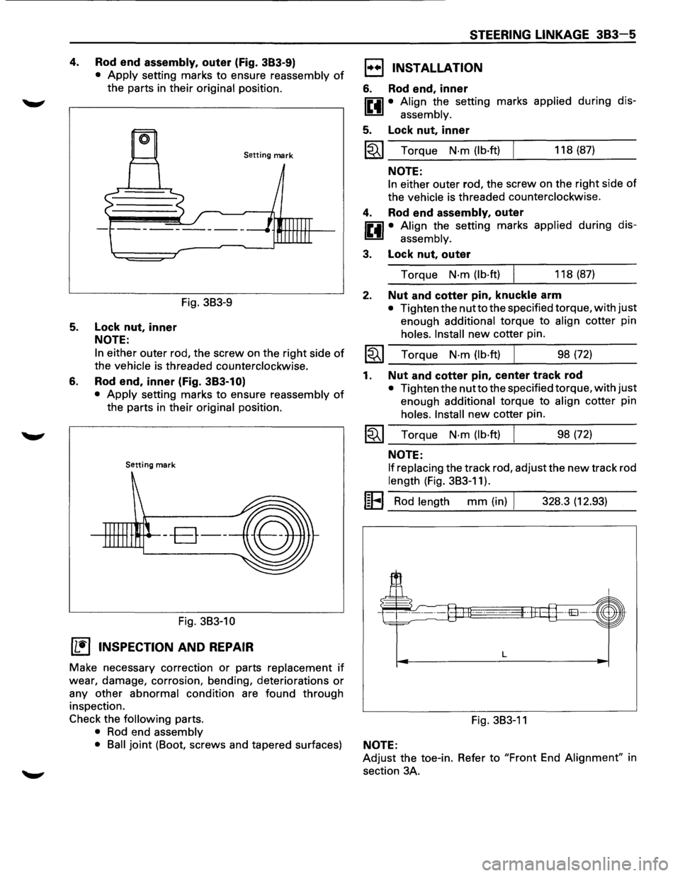
4. Rod end assembly, outer (Fig. 383-9)
• Apply setting marks to ensure reassembly of
the parts in their original position.
Setting mark
Fig. 3B3-9
5. Lock nut, inner
NOTE:
6.
In either outer rod, the screw on the right side of
the vehicle is threaded counterclockwise.
Rod end, inner (Fig. 383-1 O)
• Apply setting marks to ensure reassembly of
the parts in their original position.
Setting mark
--B--
Fig. 3B3-10
(1!] INSPECTION AND REPAIR
Make necessary correction or parts replacement if
wear, damage, corrosion, bending, deteriorations or
any other abnormal condition are found through
inspection.
Check the
following parts.
• Rod end assembly
STEERING LINKAGE 383-5
1••1 INSTALLATION
6. Rod end, inner
IP.il • Align the setting marks applied during dis-
~ assembly.
5. Lock nut, inner
~~~ Torque N·m (lb·ft) 118 (87)
NOTE:
In either outer rod, the screw on the right side of
the vehicle is threaded counterclockwise.
4. Rod end assembly, outer
IP.il • Align the setting marks applied during dis-
~ assembly.
3. Lock nut, outer
Torque N·m (lb·ft) 118 (87)
2. Nut and cotter pin, knuckle arm
• Tighten the nutto the specified torque, with just
enough additional torque to align cotter pin
holes. Install new cotter pin.
~~~ Torque N·m (lb·ft) ___ ______._ ___ _ 98 (72)
1. Nut and cotter pin, center track rod
• Tighten the nutto the specified torque, with just
enough additional torque to align cotter pin
holes. Install new cotter pin.
~~~ Torque N·m (lb·ft) 98 (72)
NOTE:
If replacing
the track rod, adjust the new track rod
length (Fig. 3B3-11).
I~EI Rod length mm (in) I 328.3 (12.93)
L
Fig. 3B3-11
• Ball joint (Boot, screws and tapered surfaces) NOTE:
Adjust the toe-in. Refer to "Front End Alignment" in
section 3A.
Page 165 of 1928
FRONT SUSPENSION 3C-1
SECTION 3C
FRONT SUSPENSION
'\f CAUTION:
When fasteners are removed, always reinstall them at the same location from which they were removed.
If a fastener needs to be replaced, use the correct part number fastener for that application. If the correct
part
number fastener is not available, a fastener of equal size and strength (or stronger) may be used.
Fasteners
that are not reused, and those requiring thread locking compound, will be called out. The correct
torque value must be used when installing fasteners that require it. If the above conditions are not
followed, parts or system damage could result.
Refer to section 3A in this manual for the wheel alignment procedure.
CONTENTS
General Description .. .. .. .. .. .. .. .. .. .. .. .. .. .. . 3C- 1
On-Vehicle Service .............................. 3C-3
Shock Absorber . . . . . . . . . . . . . . . . . . . . . . . . . . . . . . . 3C-3
Stabilizer Bar . .. .. . .. .. ..
.. . .. .. . .. .. .. . .. .. .. . 3C- 4
Torsion Bar
.................................... 3C-5
Knuckle . .
. . . . . . . . . . . . . . . . . . . . . . . . . . . . . . . . . . . . . . 3C-7
Upper
Control Arm ........................... 3C-10
Lower Control Arm ........................... 3C-13
Upper Ball Joint ............................... 3C- 16
Lower
Ball Joint ............................... 3C-18
Main Data and Specifications.................. 3C-20
General
Specifications . .
. . . . . . . . . . . . . . . . . . . . . 3C-
20
Torque Specifications ........................ 3C-21
Special Tools ..................................... 3C-22
GENERAL DESCRIPTION
The front suspension is designed to allow each wheel
to compensate for changes in the road surface level
without greatly affecting the opposite wheel. Each
wheel is independently connected to the frame by a
steering
knuckle, ball joint assemblies, and upper and
lower control arms. The front wheels are held in
proper relationship to each other by two outer track
rods
which are connected to steering arms on the
knuckles and to a center track rod.
All models have a front suspension system consisting
of control arms, stabilizer bar, shock absorber and a
torsion bar. The front end of the torsion bar is
attached
to the lower control arm. The rear of the
torsion bar is mounted into a height control arm at the
crossmember. Vehicle trim height is controlled by
adjusting this arm.
Shock absorbers are
mounted between the brackets
on the
frame and the lower control arms. The lower
portion of each shock absorber is attached to the
lower control arm by a bolt and nut. The upper portion
of each shock absorber extends through a frame
bracket and is secured with two rubber bushings,
three retainers and a nut.
Ball joint assemblies are bolted to the outer end of the
upper and lower control arm and are attached to the
steering
knuckle by nuts and cotter pins.
The
inner ends of the upper control arm have pressed
in bushings.
Bolts, passing through the bushing,
attach the control arm to the frame. The inner ends of
the lower control arm are attached to the frame by
bolts passing through the bushings, which are
pressed in the frame.
Side
roll of the front suspension is controlled by a
spring steel stabilizer bar. It is mounted in rubber
bushings, which are held to the crossmember by
brackets. The ends of the stabilizer bar are connected
to the lower control arms by links.
Page 171 of 1928
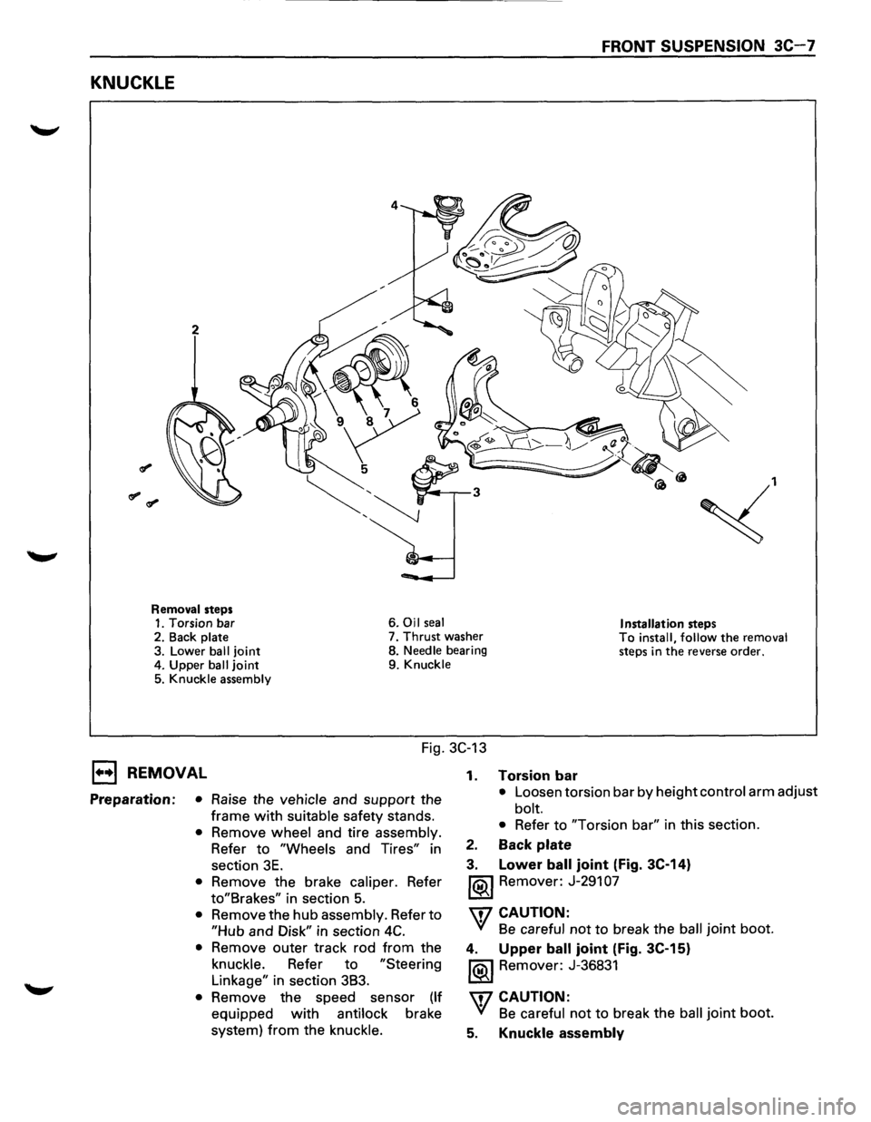
FRONT SUSPENSION 3C-7
KNUCKLE
2
~,
Removal steps 1. Torsion bar 6. Oil seal Installation steps 2.
Back plate 7. Thrust washer To install, follow the removal steps in the reverse order. 3. Lower ball joint 8. Needle bearing
4. Upper
ball joint 9. Knuckle
5. Knuckle assembly
Fig. 3C-13
1••1 REMOVAL
Preparation: • Raise the vehicle and support the
frame
with suitable safety stands.
• Remove wheel and tire assembly.
Refer to
"Wheels and Tires" in
section
3E.
• Remove the brake caliper. Refer
to"Brakes" in section 5.
• Remove the hub assembly. Refer to
"Hub and Disk" in section 4C.
• Remove outer track rod from the
knuckle. Refer to
"Steering
Linkage" in section 3B3.
• Remove the speed sensor (If
equipped with antilock brake
system)
from the knuckle. 1.
Torsion bar
• Loosen
torsion bar by height control arm adjust
bolt.
• Refer to "Torsion bar" in this section.
2. Back plate
3. Lower ball joint (Fig. 3C-14)
1®.1 Remover: J-291 07
'\f7 CAUTION:
'(! Be careful not to break the ball joint boot.
4. Upper ball joint (Fig. 3C-15)
1®.1 Remover: J-36831
'\f7 CAUTION:
'(! Be careful not to break the ball joint boot.
5. Knuckle assembly
Page 174 of 1928
3C-1 0 FRONT SUSPENSION
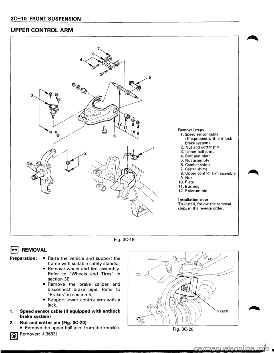
UPPER CONTROL ARM
3
V' , I
Fig. 3C-19
1••1 REMOVAL
Preparation: • Raise the vehicle and support the
frame
with suitable safety stands.
• Remove wheel and tire assembly.
Refer
to "Wheels and Tires" in
section
3E.
• Remove the brake caliper and
disconnect brake pipe. Refer
to
"Brakes" in section 5.
• Support lower control arm with a
jack.
1. Speed sensor cable (If equipped with antilock
brake system)
2.
Nut and cotter pin (Fig. 3C-20)
• Remove the upper ball joint from the knuckle.
1®.1 Remover: J-36831
Removal steps 1. Speed sensor cable
(If equipped with anti lock
brake system)
2. Nut and cotter pin 3. Upper ball joint 4. Bolt and plate 5. Nut assembly 6. Camber shims
7. Caster shims
8.
Upper control arm assembly
9. Nut 10. Plate 11. Bushing
12. Fulcrum pin
Installation steps To install, follow the removal steps in the reverse order.
Fig. 3C-20
Ill