lock ISUZU TROOPER 1995 Owner's Manual
[x] Cancel search | Manufacturer: ISUZU, Model Year: 1995, Model line: TROOPER, Model: ISUZU TROOPER 1995Pages: 1928
Page 96 of 1928
10-8 COMPRESSOR OVERHAUL
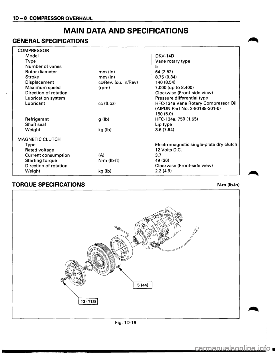
MAIN DATA AND SPECIFICATIONS
GENERAL SPECIFICATIONS
COMPRESSOR
Model
Type
Number of vanes
Rotor
diameter
Stroke
Displacement
Maximum speed
Direction
of rotation
Lubrication system
Lubricant
Refrigerant
Shaft seal
Weight
MAGNETIC CLUTCH
Type
Rated voltage
Current consumption
Starting torque
Direction of rotation
Weight
TORQUE SPECIFICATIONS
mm (in)
mm (in)
cc/Rev. (cu. in/Rev)
(rpm)
cc (fl.oz)
g (lb)
kg (lb)
(A)
N·m (lb·ft)
kg (lb)
Fig. 1D-16 DKV-14D
Vane
rotary type
5 64 (2.52)
8.75
(0.34)
140
(8.54)
7,000 (up to 8,400)
Clockwise
(Front-side view)
Pressure
differential type
HFC-134a Vane Rotary Compressor Oil
(AIPDN
Part No. 2-90188-301-0)
150 (5.0)
HFC-134a, 750 (1.65)
Lip
type
3.6 (7.94)
Electromagnetic single-plate dry clutch
12 Volts D.C.
3.7
49 (36)
Clockwise (Front-side view)
2.2 (4.9)
N·m (lb·in)
•
Page 109 of 1928
SHEET METAL 2C-1
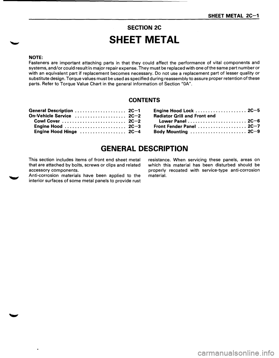
SECTION 2C
SHEET METAL
NOTE:
Fasteners are important attaching parts in that they could affect the performance of vital components and
systems,
and/or could result in major repair expense. They must be replaced with one of the same part number or
with an equivalent part if replacement becomes necessary. Do not use a replacement part of lesser quality or
substitute design. Torque values must be used as specified during reassembly to assure proper retention of these
parts. Refer
to Torque Value Chart in the general information of Section "OA".
CONTENTS
General Description . . . . . . . . . . . . . . . . . . . . 2C-1
On-Vehicle Service . . . . . . . . . . . . . . . . . . . . 2C-2
Cowl Cover . . . . . . . . . . . . . . . . . . . . . . . . . 2C-2
Engine Hood . . . . . . . . . . . . . . . . . . . . . . . . 2C-3
Engine Hood Hinge . . . . . . . . . . . . . . . . . . 2C-4
Engine Hood Lock .................... 2C-5
Radiator Grill and Front end
Lower Panel
....................... 2C-6
Front Fender Panel ................... 2C-7
Body Mounting ...................... 2C-9
GENERAL DESCRIPTION
This section includes items of front end sheet metal
that are attached by bolts, screws
or clips and related
accessory components.
Anti-corrosion materials have been applied to the
interior surfaces
of some metal panels to provide rust resistance.
When servicing these panels, areas on
which this material has been disturbed should
be
properly recoated with service-type anti-corrosion
material.
Page 111 of 1928
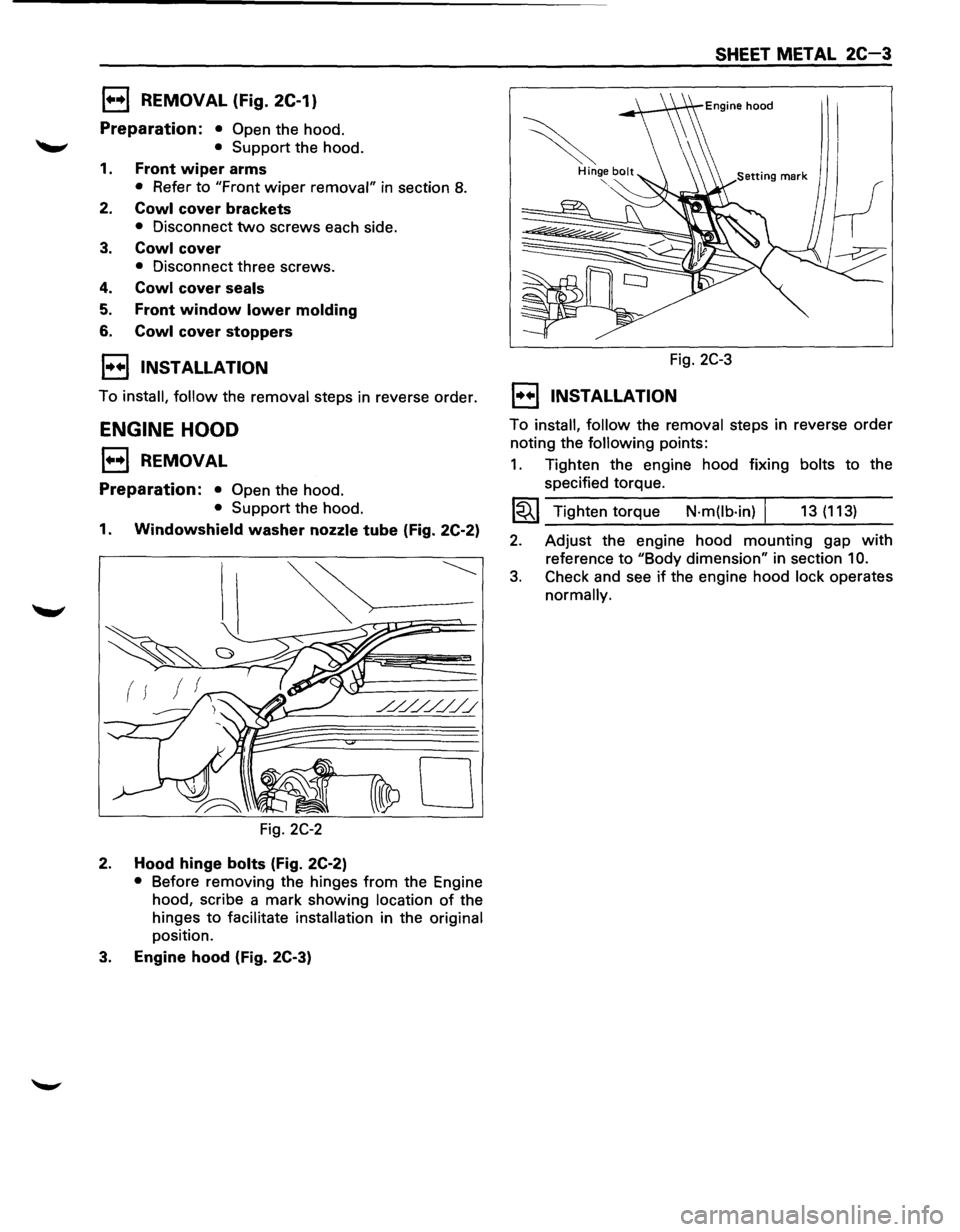
1••1 REMOVAL (Fig. 2C-1)
Preparation: • Open the hood.
'-"' • Support the hood.
1. Front wiper arms
• Refer to "Front wiper removal" in section 8.
2. Cowl cover brackets
• Disconnect two screws each side.
3. Cowl cover
• Disconnect three screws.
4. Cowl cover seals
5. Front window lower molding
6. Cowl cover stoppers
I•• I INSTALLATION
To install, follow the removal steps in reverse order.
ENGINE HOOD
1••1 REMOVAL
Preparation: • Open the hood.
• Support the hood.
1. Windowshield washer nozzle tube (Fig. 2C-2)
( f
0
Fig. 2C-2
2. Hood hinge bolts (Fig. 2C-2)
• Before removing the hinges from the Engine
hood, scribe a mark showing
location of the
hinges
to facilitate installation in the original
position.
3. Engine hood (Fig. 2C-3)
SHEET METAL 2C-3
Fig. 2C-3
1••1 INSTALLATION
To install, follow the removal steps in reverse order
noting the following points:
1. Tighten the engine hood fixing bolts to the
specified torque.
1~1 Tighten torque N·m(lb·in) I 13 (113)
2. Adjust the engine hood mounting gap with
reference to "Body dimension" in section 10.
3. Check and see if the engine hood lock operates
normally.
Page 113 of 1928
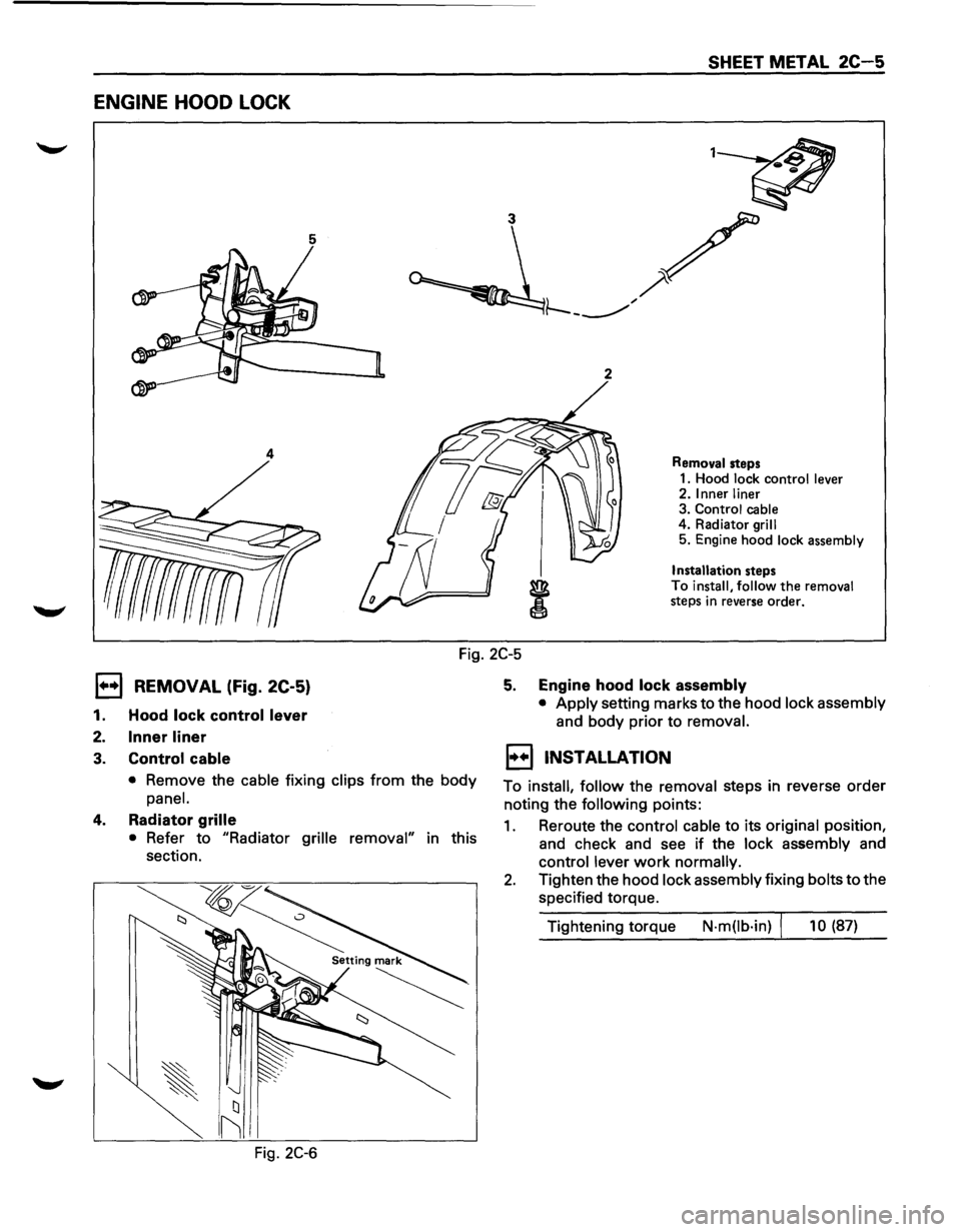
ENGINE HOOD LOCK
5
2
4
SHEET METAL 2C-5
Removal steps
1. Hood lock control lever
2. Inner liner
3. Control cable
4. Radiator
grill
5. Engine hood lock assembly
Installation steps
To install, follow the removal
steps in reverse order.
Fig. 2C-5
1••1 REMOVAL (Fig. 2C-5)
1. Hood lock control lever
2. Inner liner
3. Control cable
• Remove the cable fixing clips from the body
panel.
4. Radiator grille
• Refer to "Radiator grille removal" in this
section.
Fig.
2C-6
5. Engine hood lock assembly
• Apply setting marks to the hood lock assembly
and body prior to removal.
EJ INSTALLATION
To install, follow the removal steps in reverse order
noting the
following points:
1. Reroute the control cable to its original position,
and check and see if the
lock assembly and
control lever work normally.
2. Tighten the hood lock assembly fixing bolts to the
specified torque.
Tightening torque
N·m(lb·in) I 10 (87)
Page 127 of 1928
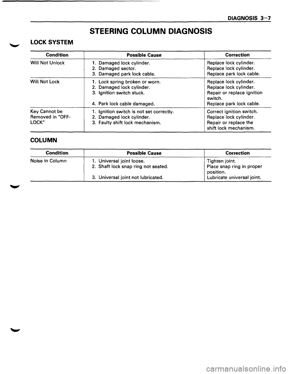
LOCK SYSTEM
Condition
Will Not Unlock
Will Not Lock
Key
Cannot be
Removed in "OFF-
LOCK"
COLUMN
Condition
Noise in Column
DIAGNOSIS 3-7
STEERING COLUMN DIAGNOSIS
Possible Cause
1. Damaged lock cylinder.
2. Damaged sector.
3. Damaged park lock cable.
1. Lock spring broken or worn.
2. Damaged lock cylinder.
3. Ignition switch stuck.
4. Park lock cable damaged.
1. Ignition switch is not set correctly.
2. Damaged lock cylinder.
3. Faulty shift lock mechanism.
Possible Cause
1. Universal joint loose.
2. Shaft lock snap ring not seated.
3. Universal joint not lubricated.
Correction
Replace lock cylinder.
Replace lock cylinder.
Replace park lock cable.
Replace lock cylinder.
Replace lock cylinder.
Repair
or replace ignition
switch.
Replace park lock cable.
Correct ignition switch.
Replace lock cylinder.
Repair
or replace the
shift lock mechanism.
Correction
Tighten joint.
Place snap ring in proper
position.
Lubricate universal joint.
Page 129 of 1928
DIAGNOSIS 3-9
TIRE DIAGNOSIS
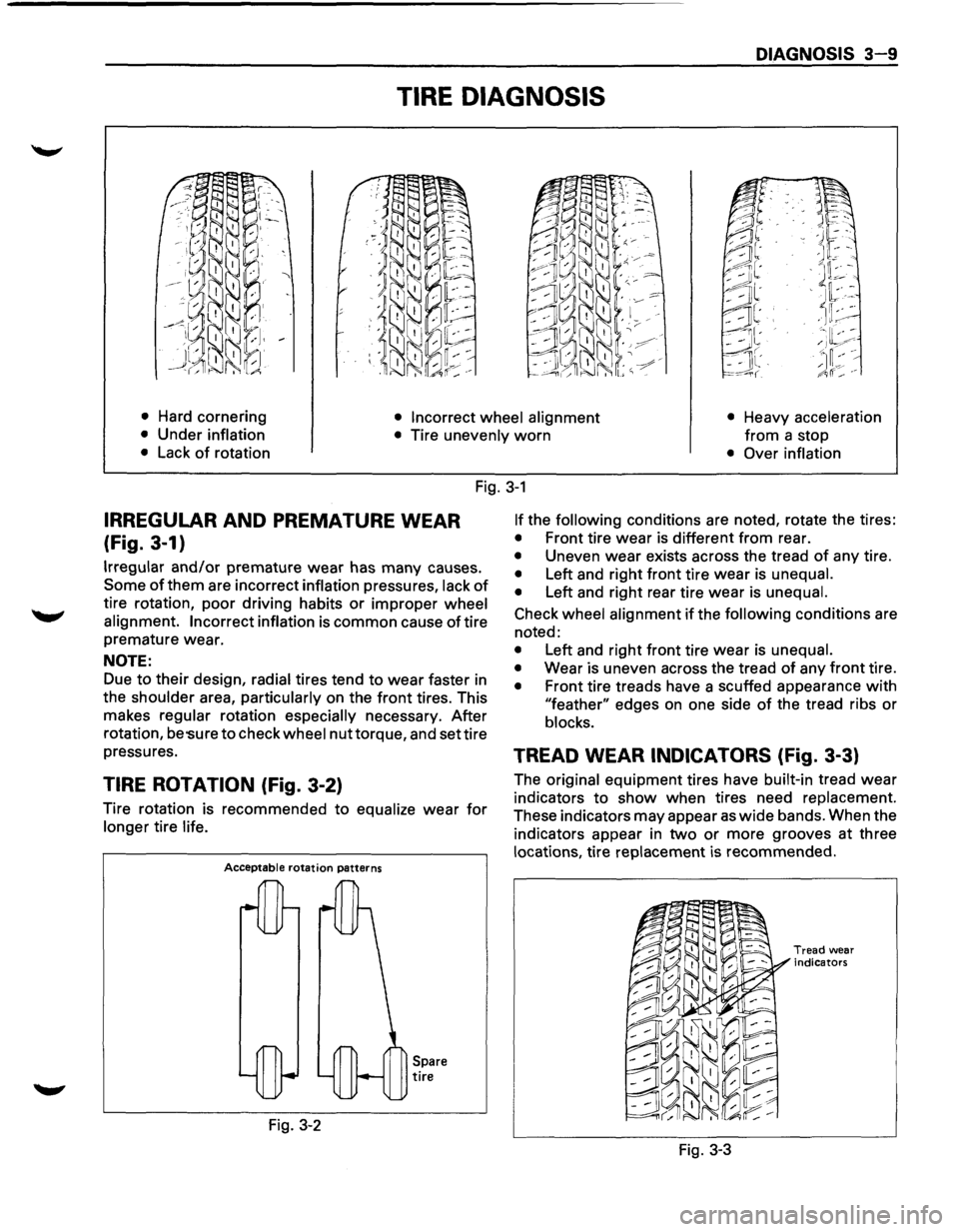
• Hard cornering • Incorrect wheel alignment • Heavy acceleration
from a
stop • Under inflation
• Tire unevenly worn
• Lack of rotation • Over inflation
Fig. 3-1
IRREGULAR AND PREMATURE WEAR
(Fig. 3-1)
Irregular and/or premature wear has many causes.
Some of them are incorrect inflation pressures, lack of
tire rotation, poor driving habits or improper wheel
alignment. Incorrect inflation
is common cause of tire
premature wear.
NOTE:
Due to their design, radial tires tend to wear faster in
the
shoulder area, particularly on the front tires. This
makes
regular rotation especially necessary. After
rotation,
be 'Sure to check wheel nut torque, and set tire
pressures.
TIRE ROTATION (Fig. 3-2)
Tire rotation is recommended to equalize wear for
longer tire life.
Acceptable rotation patterns
Fig. 3-2
Spare tire
If the following conditions are noted, rotate the tires:
• Front tire wear is different from rear.
• Uneven wear exists across the tread of any tire.
• Left and right front tire wear is unequal.
•
Left and right rear tire wear is unequal.
Check wheel alignment if the following conditions are
noted:
• Left and right front tire wear is unequal.
•
Wear is uneven across the tread of any front tire.
• Front tire treads have a scuffed appearance with
"feather" edges on one side of the tread ribs or
blocks.
TREAD WEAR INDICATORS (Fig. 3-3)
The original equipment tires have built-in tread wear
indicators to show when tires need replacement.
These indicators may appear as wide bands. When the
indicators appear in
two or more grooves at three
locations, tire replacement is recommended.
Fig. 3-3
Tread wear
indicators
Page 133 of 1928
FRONT END ALIGNMENT 3A-1
SECTION3A
FRONT END ALIGNMENT
CAUTION:
When fasteners are removed, always reinstall them at the same location from which they were removed. If
a fastener needs to be replaced, use the correct part number fastener for that application. If the correct part
number fastener is not available, a fastener of equal size and strength (or stronger) may be used. Fasteners
that are not reused, and those requiring thread locking compound will be called out. The correcttorque value
must be used when installing fasteners that require it. If the above conditions are not followed, parts or
system damage could result.
CONTENTS
General Description ................................ 3A-1
Camber Adjustment ............................. 3A-4
Definition of Terms .............................. 3A·2 Toe-in Adjustment ............................... 3A-5
On-Vehicle Service ................................. 3A-3 Maximum Steering Angle Adjustment ....... 3A-5
Inspection ......................................... 3A-3 Main Data and Specifications ..................... 3A-6
Trim Height Adjustment ........................ 3A-3 General Specifications .......................... 3A-6
Caster
Adjustment ............................... 3A-3 Torque Specifications ........................... 3A-6
GENERAL DESCRIPTION
"Front End Alignment" refers to the angular
relationship between the front wheels, the front
suspension attaching parts and the ground.
Proper front end alignment must be maintained in
order to insure efficient steering, good directional
stability and to prevent abnormal tire wear.
The
most important factors of front end alignment are
wheel toe-in, wheel camber and axle caster.
Page 137 of 1928
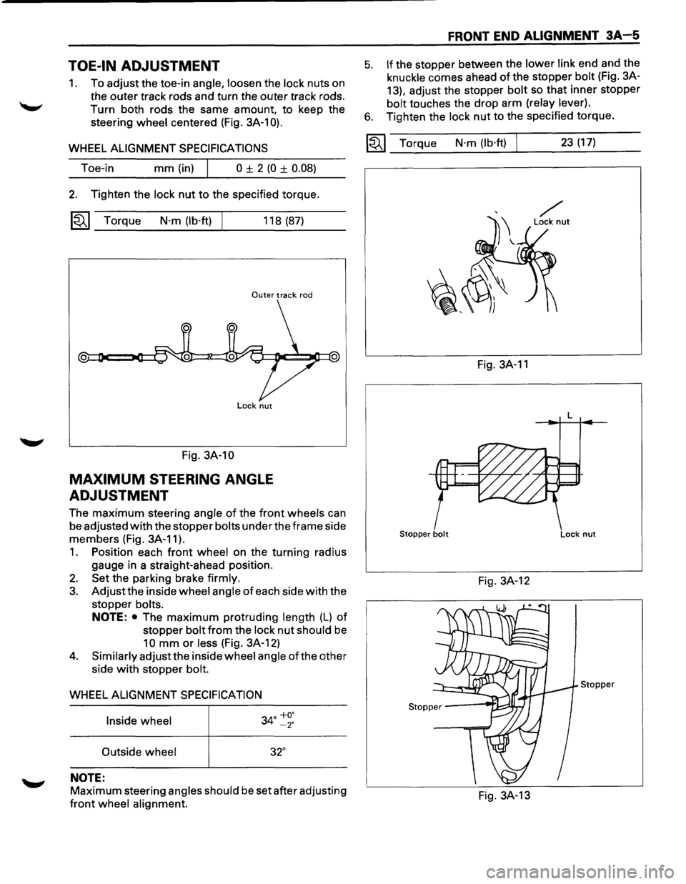
TOE-IN ADJUSTMENT
1. To adjust the toe-in angle, loosen the lock nuts on
the outer track rods and turn the outer track rods.
Turn both rods the same amount, to keep the
steering
wheel centered (Fig. 3A-1 0).
WHEEL ALIGNMENT SPECIFICATIONS
Toe-in mm (in) I 0 ± 2 (0 ± 0.08)
2. Tighten the lock nut to the specified torque.
~~~ Torque N·m (lb·ft) 118 (87)
Outer track rod
Lock nut
Fig. 3A-10
MAXIMUM STEERING ANGLE
ADJUSTMENT
The maximum steering angle of the front wheels can
be adjusted
with the stopper bolts under the frame side
members (Fig. 3A-11 ).
1. Position each front wheel on the turning radius
gauge in a straight-ahead position.
2. Set the parking brake firmly.
3. Adjust the inside wheel angle of each side with the
stopper
bolts.
NOTE: • The maximum protruding length (L) of
stopper bolt from the lock nut should be
10 mm or less (Fig. 3A-12)
4. Similarly adjust the inside wheel angle of the other
side
with stopper bolt.
WHEEL ALIGNMENT SPECIFICATION
Inside wheel
34° ~~:
Outside wheel 32°
NOTE:
Maximum steering angles should be set after adjusting
front wheel alignment.
FRONT END ALIGNMENT 3A-5
5. If the stopper between the lower link end and the
knuckle comes ahead of the stopper bolt (Fig. 3A-
13), adjust the stopper
bolt so that inner stopper
bolt touches the drop arm (relay lever).
6. Tighten the lock nut to the specified torque.
~~~ Torque N·m (lb·ft) 23 (17)
Fig. 3A-11
L
Stopper bolt Lock nut
Fig. 3A-12
Stopper
Fig. 3A-13
Page 139 of 1928
POWER STEERING GEAR AND PUMP 381 -1
SECTION 381
POWER STEERING GEAR AND PUMP
w CAUTION:
When fasteners are removed, always reinstall them at the same location from which they were removed.
If a fastener needs to be replaced, use the correct part number fastener for that application. If the correct
part
number fastener is not available, a fastener of equal size and strength (or stronger) may be used.
Fasteners
that are not reused, and those requiring thread locking compound, will be called out. The correct
torque value must be used when installing fasteners that require it. If the above conditions are not
followed, parts or system damage could result.
CONTENTS
General Description ............................ 3B1- 1
Steering Wheel Free Play Adjustment .... 3B1-5
Power Steering
Gear........................ 3B1-1
Steering Gear ................................ 3B1-6
Hydraulic Pump .............................. 3B1- 1
Power Steering Pump ...................... 3B1-8
Pressure Switch
............................. 3B1-1
Unit Repair ...................................... 3B1- 9
Power Steering System Test
................. 3B1-3
Steering Gear ................................ 3B1-9
On-Vehicle Service ............................. 3B1- 4
Power Steering Pump ...................... 3B1-14
Maintenance
................................. 3B1- 4
Main Data and Specifications ................ 3B1-17
Fluid Level .................................... 3B1- 4 General Specifications ...................... 3B1-17
Bleeding The Power Steering System .... 3B1-4
Torque Specifications ....................... 3B1-17
Bleeding Procedure ......................... 3B1-4 Special Tools.................................... 3B1-18
Flushing The Power Steering System .... 3B1-4
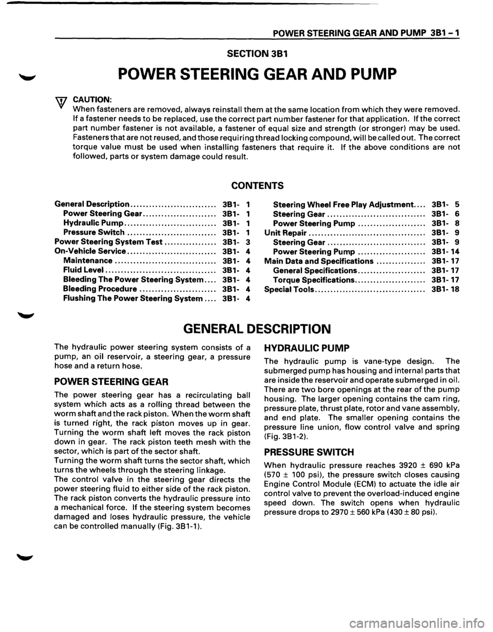
GENERAL DESCRIPTION
The hydraulic power steering system consists of a
pump, an oil reservoir, a steering gear, a pressure
hose and a return hose.
POWER STEERING GEAR
The power steering gear has a recirculating ball
system which acts as a rolling thread between the
worm shaft and the rack piston. When the worm shaft
is
turned right, the rack piston moves up in gear.
Turning the worm shaft left moves the rack piston
down in gear. The rack piston teeth mesh with the
sector, which is part ofthe sector shaft.
Turning the worm shaft turns the sector shaft, which
turns the wheels through the steering linkage.
The control valve in the steering gear directs the
power steering fluid to either side of the rack piston.
The rack
piston converts the hydraulic pressure into
a mechanical force. If the steering system becomes
damaged and loses hydraulic pressure, the vehicle
can be controlled manually (Fig. 381-1).
HYDRAULIC PUMP
The hydraulic pump is vane-type design. The
submerged pump has housing and internal parts that
are inside the reservoir and operate submerged in oil.
There are two bore openings at the rear of the pump
housing. The larger opening contains the cam ring,
pressure
plate, thrust plate, rotor and vane assembly,
and end plate. The smaller opening contains the
pressure
line union, flow control valve and spring
(Fig. 381-2).
PRESSURE SWITCH
When hydraulic pressure reaches 3920 ± 690 kPa
(570 ± 100 psi), the pressure switch closes causing
Engine
Control Module (ECM) to actuate the idle air
control valve to prevent the overload-induced engine
speed down. The switch opens
when hydraulic
pressure drops to 2970 ± 560 kPa (430 ± 80 psi).
Page 142 of 1928
381 - 4 POWER STEERING GEAR AND PUMP
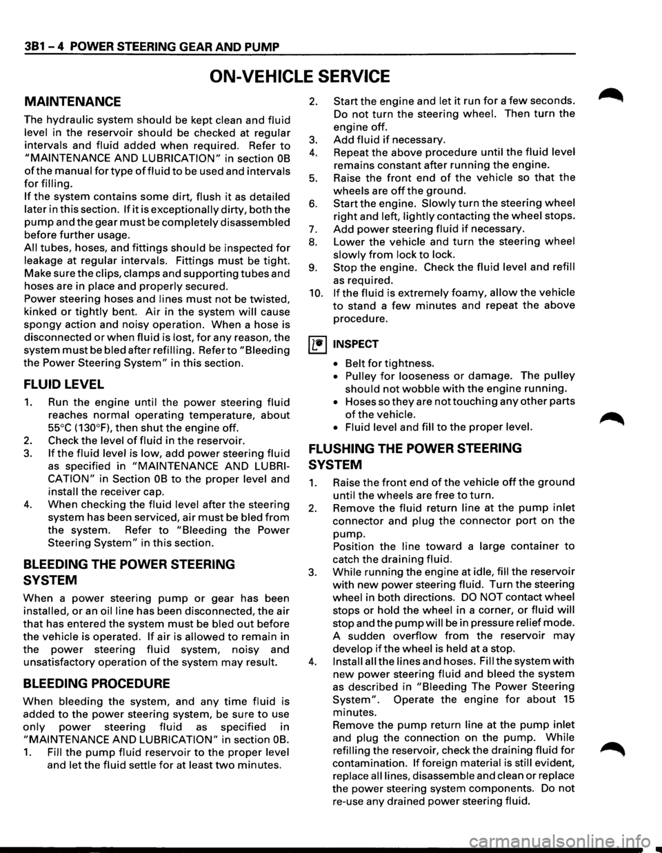
ON-VEHICLE SERVICE
MAINTENANCE
The hydraulic system should be kept clean and fluid
level in the reservoir should be checked at regular
intervals
and fluid added when required. Refer to
"MAINTENANCE AND LUBRICATION" in section OB
ofthe manual for type offluid to be used and intervals
for filling.
If the system contains some dirt, flush it as detailed
later
in this section. If it is exceptionally dirty, both the
pump and the gear must be completely disassembled
before further usage.
All tubes, hoses, and fittings should be inspected for
leakage at regular intervals. Fittings must be tight.
Make sure the clips, clamps and supporting tubes and
hoses are in
place and properly secured.
Power steering hoses and lines must not be twisted,
kinked or tightly bent. Air in the system will cause
spongy action and noisy operation. When a hose is
disconnected
or when fluid is lost, for any reason, the
system must be bled after refilling. Refer to "Bleeding
the Power Steering System" in this section.
FLUID LEVEL
1. Run the engine until the power steering fluid
reaches normal operating temperature, about
55°C (130°F), then shut the engine off.
2. Check the level of fluid in the reservoir.
3. If the fluid level is low, add power steering fluid
as specified in "MAINTENANCE AND LUBRI
CATION" in Section OB to the proper level and
install the receiver cap.
4. When checking the fluid level after the steering
system has been serviced,
air must be bled from
the system. Refer to "Bleeding the Power
Steering
System" in this section.
BLEEDING THE POWER STEERING
SYSTEM
When a power steering pump or gear has been
installed, or an oil line has been disconnected, the air
that has entered the system must be bled out before
the vehicle is operated. If air is allowed to remain in
the power steering fluid system, noisy and
unsatisfactory operation of the system may result.
BLEEDING PROCEDURE
When bleeding the system, and any time fluid is
added
to the power steering system, be sure to use
only power steering fluid as specified in
"MAINTENANCE AND LUBRICATION" in section OB.
1. Fill the pump fluid reservoir to the proper level
and let the fluid settle for at least two minutes.
2. Start the engine and let it run for a few seconds.
Do
not turn the steering wheel. Then turn the
engine off.
3. Add fluid if necessary.
4. Repeat the above procedure until the fluid level
remains constant after running the engine.
5. Raise the front end of the vehicle so that the
wheels are off the ground.
6. Start the engine. Slowly turn the steering wheel
right and left, lightly contacting the wheel stops.
7. Add power steering fluid if necessary.
8. Lower the vehicle and turn the steering wheel
slowly from lock to lock.
9. Stop the engine. Check the fluid level and refill
as required.
10.
If the fluid is extremely foamy, allow the vehicle
to stand a few minutes and repeat the above
procedure.
~ INSPECT
• Belt for tightness.
• Pulley for looseness or damage. The pulley
should not wobble with the engine running.
• Hoses so they are not touching any other parts
of the vehicle.
• Fluid level
and fill to the proper level.
FLUSHING THE POWER STEERING
SYSTEM
1. Raise the front end of the vehicle off the ground
until the wheels are free to turn.
2. Remove the fluid return line at the pump inlet
connector and plug the connector port on the
pump.
Position the line toward a large container to
catch the draining fluid.
3. While running the engine at idle, fill the reservoir
with new power steering fluid. Turn the steering
wheel in both directions. DO NOT contact wheel
stops or hold the wheel in a corner, or fluid will
stop and the pump will be in pressure relief mode.
A sudden
overflow from the reservoir may
develop if the wheel is held at a stop.
4. Install all the lines and hoses. Fill the system with
new power steering fluid and bleed the system
as described in "Bleeding The Power Steering
System". Operate the engine for about 15
minutes.
Remove the
pump return line at the pump inlet
and plug the connection on the pump. While
refilling the reservoir, check the draining fluid for
contamination. If foreign material is still evident,
replace all lines, disassemble and clean or replace
the power steering system components. Do not
re-use any drained power steering fluid.
~
~