lock ISUZU TROOPER 1995 Service Manual
[x] Cancel search | Manufacturer: ISUZU, Model Year: 1995, Model line: TROOPER, Model: ISUZU TROOPER 1995Pages: 1928
Page 180 of 1928
3C-16 FRONT SUSPENSION
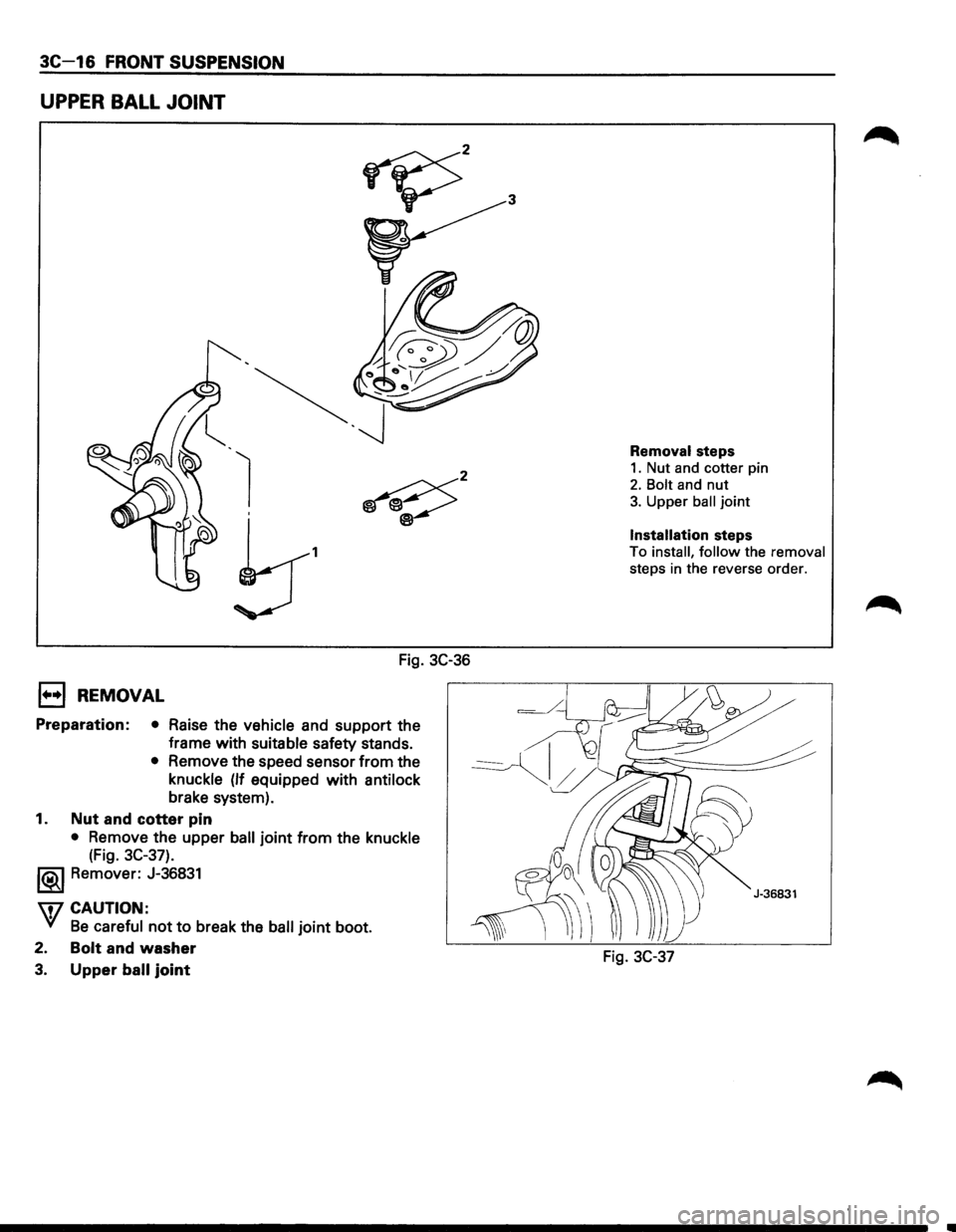
UPPER BALL JOINT
1
Fig. 3C-36
E) REMOVAL
Preparation: • Raise the vehicle and support the
frame with
suitable safety stands.
• Remove the speed sensor from the
knuckle
(If equipped with antilock
brake system).
1. Nut and cotter pin
• Remove the upper ball joint from the knuckle
(Fig. 3C-37).
l®..l Remover: J-36831
\fl CAUTION:
VI Be careful not to break the ball joint boot.
2.
Bolt and washer
3. Upper ball joint
Removal steps
1. Nut and cotter pin
2. Bolt and nut
3. Upper ball joint
Installation steps
To install, follow the removal
steps in the reverse order.
Fig. 3C-37
Page 187 of 1928
REAR SUSPENSION 30-1
SECTION 30
REAR SUSPENSION
WCAUTION:
VI When fasteners are removed, always reinstall them at the same location from which they were removed. If a
fastener needs to be
replaced, use the correct part number fastener for that application. If the correct part
number fastener is
not available, a fastener of equal size and strength (or stronger) may be used. Fasteners
that are
not reused, and those requiring thread locking compound, will be called out. The correct torque
value must be used when installing fasteners that require it. If the above conditions are not followed, parts or
system damage could result.
CONTENTS
General Description . . . . . . . . . . . . . . . . . . . . 3D-2
On-Vehicle Service .................... 3D-3
Coil Spring . .
. . . . . . . . . . . . . . . . . . . . . . . 3D· 3
Shock
Absorber . . . . . . . . . . . . • . . . . . . . . 3D-5
Trailing Link . .
. . . . . . . . . . . . . . . . . . . . . . 3D-6
Center
Link . . • . . . . . . . . . . • . . . . . . . . . . . 3D-8
Lateral Rod ......................... 3D-1 0
Stabilizer Bar ........................ 3D-11
Main Data and Specifications ............ 3D-12
General Specifications ................ 3D-12
Torque Specifications
................ 30-13
Special Tools .......................... 3D-13
Page 194 of 1928
30-8 REAR SUSPENSION
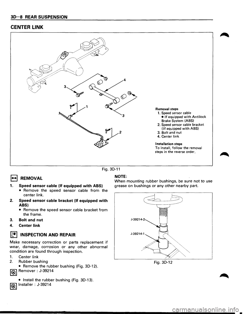
CENTER LINK
2
Removal steps
1. Speed sensor cable
• If equipped with Antilock Brake System (ABS)
2. Speed sensor
cable bracket (If equipped with ABS)
3.
Bolt and nut 4. Center link
Installation
steps
To
install, follow the removal steps in the reverse order.
1•+1 REMOVAL
Fig. 30-11
NOTE:
1.
2.
3.
Speed sensor cable (If equipped with ABS)
• Remove the speed sensor cable from the
center
link.
Speed sensor cable bracket (If equipped with
ABS)
• Remove the speed sensor cable bracket from
the frame.
Bolt and nut
4. Center link
~ INSPECTION AND REPAIR
Make necessary correction or parts replacement if
wear, damage, corrosion or any other abnormal
condition are found through inspection.
1. Center link
2. Rubber bushing
• Remove the rubber bushing (Fig. 30-12).
1®1 Remover : J-39214
• Install the rubber bushing (Fig. 30-13).
!®..I Installer : J-39214
When mounting rubber bushings, be sure not to use
grease on bushings
or any other nearby part.
J-39214-2
J-39214·1
Fig. 30-12
..
Page 201 of 1928
WHEELS AND TIRES 3E-1
SECTION 3E
WHEELS AND TIRES
W CAUTION:
When fasteners are removed, always reinstall them at the same location from which they were removed.
If a fastener needs to be replaced, use the correct part number fastener for that application. If the correct
part
number fastener is not available, a fastener of equal size and strength (or stronger) may be used.
Fasteners
that are not reused, and those requiring thread locking compound, will be called out. The correct
torque value must be used when installing fasteners that require it. If the above conditions are not
followed, parts or system damage could result.
CONTENTS
General Description . . . . . . . . . . . . . . . . . . . . . . . . . . . . . . . 3 E -1 Unit Repair .......................................... 3E-7
Diagnosis ........................................... 3E-2 Tires ............................................... 3E-7
Irregular and Premature Wear ................ 3E-2 Wheels ............................................ 3E-7
Inflation of Tires ................................. 3 E- 3 General Balance Procedure ................... 3E-8
Diagnosis List. . . . . . . . . . . . . . . . . . . . . . . . . . . . . . . . . . . . 3 E- 3 Balancing Wheel and Tire ...................... 3E-8
On-Vehicle Service ................................ 3E-6 Main Data and Specifications .................... 3E-9
Wheels ............................................ 3E-6 General Specifications ......................... 3E-9
Torque Specifications .......................... 3E-9
GENERAL DESCRIPTION
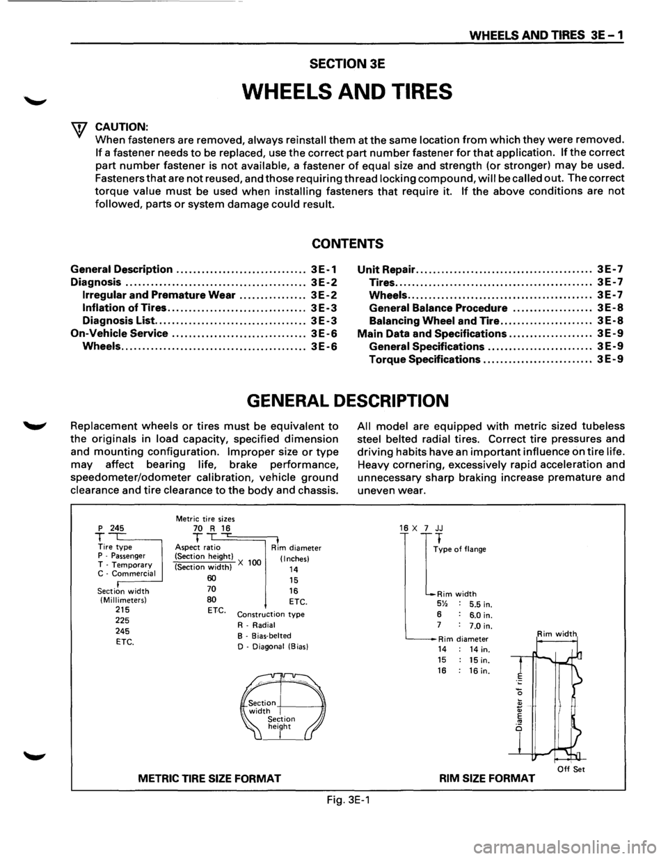
Replacement wheels or tires must be equivalent to
the originals in load capacity, specified dimension
and mounting configuration. Improper size or type
may affect bearing life, brake performance,
speedometer/odometer calibration, vehicle ground
clearance and tire clearance to the body and chassis.
p 245
T Tire type P -Passenger T -Temporary C -Commercial
Section
width (Millimeters) 215 225
245
ETC.
Metric tire sizes 70 R 16 T ,...
Aspect ratio I Rim diameter
(Section height)
(Section
width) X 100 (Inches)
14 60 70
80 ETC.
15
16 ETC.
Construction type
R-Radial
B - Bias-belted
D - Diagonal (Bias)
METRIC TIRE SIZE FORMAT
All model are equipped with metric sized tubeless
steel belted radial
tires. Correct tire pressures and
driving habits have an important influence on tire life.
Heavy cornering, excessively rapid acceleration and
unnecessary sharp braking increase
premature and
uneven wear.
16 X 7 JJ
I
~pe of flange
Rim width 5% 5.5 in.
6 6.0 in. 7 7.0 in.
Rim diameter Rim width
14 14 in. 15 15 in. 16 : 16 in.
I Off Set RIM SIZE FORMAT
Fig. 3E-1
Page 202 of 1928
3E-2 WHEELS AND TIRES
DIAGNOSIS
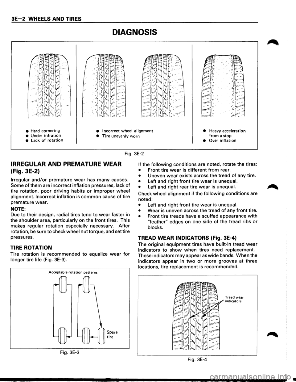
• Hard cornering • Incorrect wheel alignment
• Heavy acceleration from a stop • Under infration • Tire unevenly worn • Lack of rotation • Over inflation
Fig. 3E-2
IRREGULAR AND PREMATURE WEAR
(Fig. 3E-2)
Irregular and/or premature wear has many causes.
Some of them are incorrect inflation pressures, lack of
tire rotation, poor driving habits or improper wheel
alignment. Incorrect inflation
is common cause of tire
premature wear.
NOTE:
Due to their design, radial tires tend to wear faster in
the
shoulder area, particularly on the front tires. This
makes
regular rotation especially necessary. After
rotation, be sure to check wheel nut torque, and set tire
pressures.
TIRE ROTATION
Tire rotation is recommended to equalize wear for
longer tire life (Fig. 3E-3).
Acceptable rotation patterns
Fig. 3E-3
Spare tire
If the following conditions are noted, rotate the tires:
• Front tire wear is different from rear.
• Uneven wear exists across the tread of any tire.
• Left and right front tire wear is unequal.
•
Left and right rear tire wear is unequal.
Check wheel alignment if the following conditions are
noted:
• Left and right front tire wear is unequal.
•
Wear is uneven across the tread of any front tire.
• Front tire treads have a scuffed appearance with
"feather" edges on one side of the tread ribs or
blocks.
TREAD WEAR INDICATORS (fig. 3E-4)
The original equipment tires have built-in tread wear
indicators to show when tires need replacement.
These indicators may appear as wide bands. When the
indicators appear in
two or more grooves at three
locations, tire replacement is recommended.
Fig. 3E-4
Tread wear
indicators
•
Page 203 of 1928
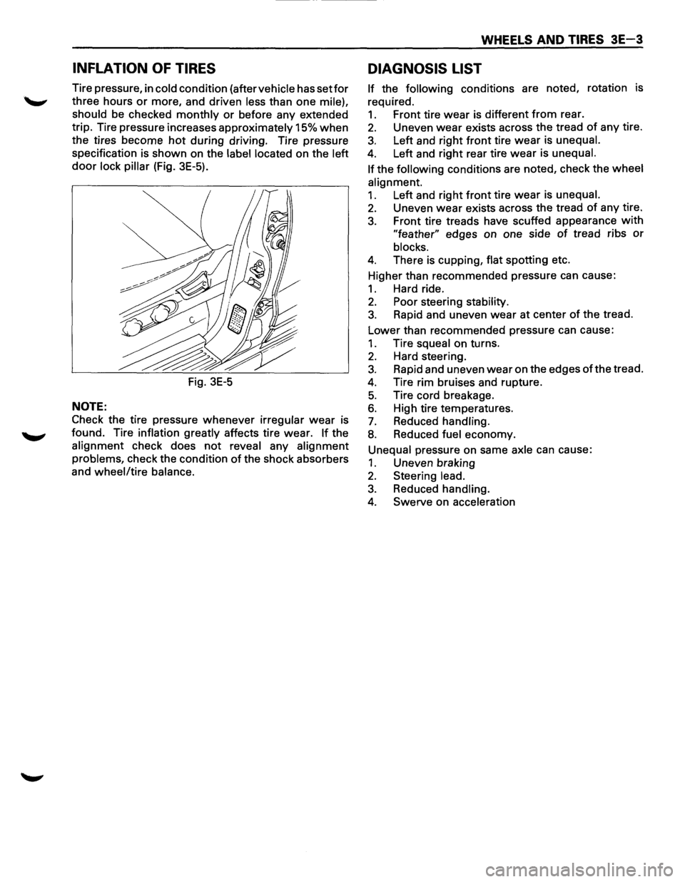
INFLATION OF TIRES
Tire pressure, in cold condition (after vehicle has setfor
three hours or more, and driven less than one mile),
should
be checked monthly or before any extended
trip. Tire pressure increases
approximately 15% when
the tires become hot during driving. Tire pressure
specification is shown on the
label located on the left
door lock pillar (Fig. 3E-5).
Fig.
3E-5
NOTE:
Check the tire pressure whenever irregular wear is
found. Tire
inflation greatly affects tire wear. If the
alignment check does not reveal any alignment
problems,
check the condition of the shock absorbers
and
wheel/tire balance.
WHEELS AND TIRES 3E-3
DIAGNOSIS LIST
If the following conditions are noted, rotation is
required.
1. Front tire wear is different from rear.
2. Uneven wear exists across the tread of any tire.
3. Left and right front tire wear is unequal.
4. Left and right rear tire wear is unequal.
If
the following conditions are noted, check the wheel
alignment.
1. Left and right front tire wear is unequal.
2. Uneven wear exists across the tread of any tire.
3. Front tire treads have scuffed appearance with
"feather" edges on one side of tread ribs or
blocks.
4. There is cupping, flat spotting etc.
Higher than recommended pressure can cause:
1. Hard ride.
2. Poor steering stability.
3. Rapid and uneven wear at center of the tread.
Lower than recommended pressure can cause:
1. Tire squeal on turns.
2. Hard steering.
3. Rapid and uneven wear on the edges of the tread.
4. Tire rim bruises and rupture.
5. Tire cord breakage.
6. High tire temperatures.
7. Reduced handling.
8. Reduced fuel economy.
Unequal pressure on same axle can cause:
1. Uneven braking
2. Steering lead.
3. Reduced handling.
4. Swerve on acceleration
Page 211 of 1928
SUPPLEMENTAL RESTRAINT SYSTEM (SRSl STEERING WHEEL & COLUMN 3F4-1
SECTION 3F4
SUPPLEMENTAL RESTRAINT SYSTEM
STEERING
WHEEL & COLUMN
W CAUTION:
When fasteners are removed, always reinstall them at the same location from which they were removed.
If a fastener needs to be replaced, use the correct part number fastener for that application. If the correct
part
number fastener is not available, a fastener of equal size and strength (or stronger) may be used.
Fasteners
that are not reused, and those requiring thread locking compound, will be called out. The correct
torque value must be used when installing fasteners that require it. If the above conditions are not
followed, parts or system damage could result.
CONTENTS
General Description .......................................... 3F4-1
Lock Cylinder Replacement ......................... 3F4-10
On-Vehicle Service
............................................ 3F4-2 Steering Column Replacement .................... 3F4-13
Special Service Precaution ........................... 3F4-2 Main Data and Specifications .......................... 3F4-17
Inflator Module Replacement ...................... 3F4-3 Torque
Specifications ................................... 3F4-17
Steering Wheel Replacement ...................... 3F4-4 Special Tools ..................................................... 3F4-17
Combination
Switch Replacement ............. 3F4-7
GENERAL DESCRIPTION
W WARNING
TO AVOID DEPLOYMENT WHEN TROUBLE
SHOOTING
THE SRS SYSTEM, DO NOT USE
ELECTRICAL TEST EQUIPMENT, SUCH AS
BATTERY-POWERED OR A/C-POWERED VOLT
METER, OHMMETER, ETC., OR ANY TYPE OF
ELECTRICAL EQUIPMENT OTHER THAN SPE
CIFIED IN THIS MANUAL. DO NOT USE A NON
POWERED
PROBE-TYPE TESTER.
INSTRUCTION IN THIS MANUAL MUST BE
FOLLOWED CAREFULLY, OTHERWISE PER
SONAL INJURY MAY RESULT.
This steering
wheel and column repair section covers
the Supplemental Restraint System (SRS) steering
column. The following repair procedures are specific
to SRS Components. When servicing a vehicle
equipped with Supplemental Restraint System, pay
close attention to all WARNINGS and CAUTIONS.
For detailed explanation about SRS, refer to Section
9J "SUPPLEMENTAL
RESTRAINT SYSTEM (SRS)" of
this manual.
The steering column has three important features in
addition to the steering function:
1. The column is energy absorbing, designed to
compress in a front-end collision to minimize the
possibility of injury to the driver of the vehicle.
2. The ignition switch and lock are mounted con
veniently on the column.
3. With the column mounted lock, the ignition and
steering operation can be
locked to prevent theft
of the vehicle.
The column may be disassembled and reassembled.
To insure the energy absorbing action, it is important
that the specified screws, bolts and nuts be used only
as designated and that they are tightened to the
specified torque.
When the column is removed from the vehicle, a
sharp
blow on the end of steering shaft or shift lever,
leaning
on the column assembly, or dropping the
assembly could shear or loosen the fasteners that
maintain column rigidity.
Page 212 of 1928
3F4-2 SUPPLEMENTAL RESTRAINT SYSTEM (SRSI STEERING WHEEL & COLUMN
ON-VEHICLE SERVICE
SPECIAL SERVICE PRECAUTIONS
\f CAUTION:
Safe
handling of Inflator modules requires fol
lowing the procedures described below for both
live and deployed modules.
\f WARNING
SAFETY PRECAUTIONS MUST BE FOLLOWED
WHEN HANDLING A DEPLOYED INFLATOR
MODULE (AIR
BAG). AFTER DEPLOYMENT, THE
INFLATOR MODULE (AIR BAG) SURFACE MAY
CONTAIN A SMALL AMOUNT OF SODIUM
HYDROXIDE,
A BY-PRODUCT OF THE DEPLOY
MENT REACTION, THAT IS IRRITATING TO THE
SKIN AND EYES. MOST OF THE POWDER ON
THE INFLATOR MODULE (AIR BAG) IS HARM
LESS. AS A PRECAUTION, WEAR GLOVES AND
SAFETY GLASSES WHEN HANDLING A DE
PLOYED INFLATOR MODULE (AIR BAG), AND
WASH YOUR HANDS WITH MILD SOAP AND
WATER AFTERWARDS.
WHEN CARRYING A
LIVE INFLATOR MODULE
(AIR
BAG), MAKE SURE THE BAG AND TRIM
COVER ARE POINTED AWAY FROM YOU.
NEVER CARRY AN INFLATOR MODULE (AIR
BAG) BY THE WIRES OR CONNECTOR ON THE
UNDERSIDE OF MODULE. IN THE CASE OF AN
ACCIDENTAL DEPLOYMENT,
THE BAG WILL
THEN DEPLOY WITH MINIMAL CHANCE OF
INJURY. WHEN PLACING A LIVE INFLATOR
MODULE (AIR
BAG) ON A BENCH OR OTHER
SURFACE, ALWAYS FACE THE BAG AND TRIM
COVER UP, AWAY FROM THE SURFACE.
NEVER
REST A STEERING COLUMN AS
SEMBLY ON
THE STEERING WHEEL WITH THE
INFLATOR MODULE (AIR BAG) FACE DOWN
AND COLUMN VERTICAL. THIS IS NECESSARY
SO THAT A FREE SPACE IS PROVIDED TO AL
LOWTHE INFLATOR MODULE (AIR BAG) TO EX
PAND
IN THE UNLIKELY EVENT OF ACCI
DENTAL DEPLOYMENT.
OTHERWISE, PERSO
NAL INJURY COULD RESULT.
For detailed explanation
about SRS, refer to Section
9J "SUPPLEMENTAL
RESTRAINT SYSTEM (SRS)" of
this manual.
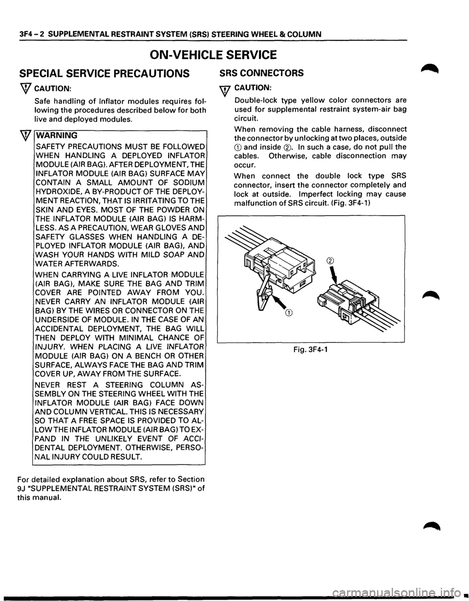
SRS CONNECTORS
w CAUTION:
Double-lock type yellow color connectors are
used
for supplemental restraint system-air bag
circuit.
When removing the cable harness, disconnect
the connector by unlocking at two places, outside
CD and inside®. In such a case, do not pull the
cables. Otherwise, cable disconnection may
occur.
When connect the double lock type SRS
connector, insert the connector completely and
lock at outside. Imperfect locking
may cause
malfunction of SRS circuit. (Fig. 3F4-1)
®
Fig. 3F4-1
•
Page 213 of 1928
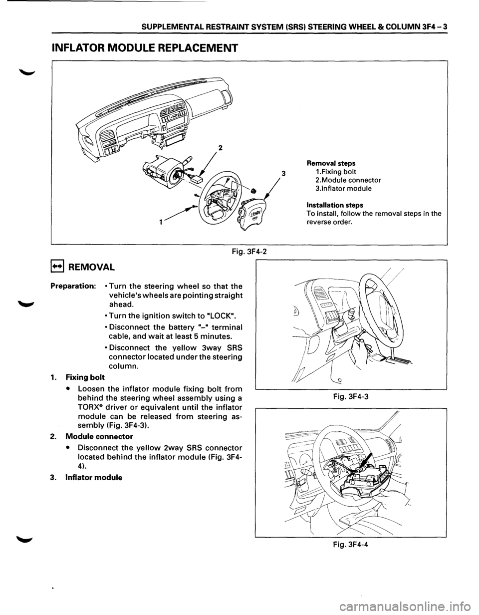
SUPPLEMENTAL RESTRAINT SYSTEM (SRS) STEERING WHEEL & COLUMN 3F4-3
INFLATOR MODULE REPLACEMENT
Fig. 3F4-2
B REMOVAL
Preparation: • Turn the steering wheel so that the
vehicle's wheels are pointing straight
._,. ahead.
1. Fixing bolt
• Turn the ignition switch to "LOCK".
•
Disconnect the battery "-" terminal
cable,
and wait at least 5 minutes.
• Disconnect the yellow 3way SRS
connector located under the steering
column.
•
Loosen the inflator module fixing bolt from
behind the steering wheel assembly using a
TORX<~> driver or equivalent until the inflator
module
can be released from steering as
sembly (Fig. 3F4-3).
2. Module connector
• Disconnect the yellow 2way SRS connector
located behind the inflator module (Fig. 3F4-
4).
3. Inflator module
Removal steps
3 1.Fixing bolt
2.Module connector
3.1nflator module
Installation steps
To install, follow the removal steps in the
reverse order.
Fig. 3F4-3
Fig. 3F4-4
Page 214 of 1928
![ISUZU TROOPER 1995 Service Manual 3F4-4 SUPPLEMENTAL RESTRAINT SYSTEM (SRS) STEERING WHEEL & COLUMN
(b!] INSPECTION AND REPAIR
\f WARNING
THE INFLATOR MODULE SHOULD ALWAYS BE
CARRIED WITH THE URETHANE COVER AWAY
FROM YOUR BODY](/img/61/57183/w960_57183-213.png "ISUZU TROOPER 1995 Service Manual 3F4-4 SUPPLEMENTAL RESTRAINT SYSTEM (SRS) STEERING WHEEL & COLUMN
(b!] INSPECTION AND REPAIR
\f WARNING
THE INFLATOR MODULE SHOULD ALWAYS BE
CARRIED WITH THE URETHANE COVER AWAY
FROM YOUR BODY")
3F4-4 SUPPLEMENTAL RESTRAINT SYSTEM (SRS) STEERING WHEEL & COLUMN
(b!] INSPECTION AND REPAIR
\f' WARNING
THE INFLATOR MODULE SHOULD ALWAYS BE
CARRIED WITH THE URETHANE COVER AWAY
FROM YOUR BODY AND SHOULD ALWAYS BE
LAID ON A FLAT SURFACE WITH THE URE
THANE SIDE UP. THIS IS NECESSARY BE
CAUSE A FREE SPACE IS PROVIDED TO ALLOW
THE AIR CUSHION TO EXPAND IN THE UN
LIKELYEVENT OF ACCIDENTAL DEPLOYMENT.
OTHERWISE, PERSONAL INJURY
MAY RESULT
(FIG. 3F4-5).
Fig. 3F4-5
The
Inflator module consists of a cover, air bag,
inflator, and retainer.
Inspect the Inflator module
mainly for the following:
1) Check for holes, cracks, severe blemishes and
deformation on the cover.
2) Check that the retainer is not deformed.
3) Check for defects such as damage and breakage in
the lead
wire ofthe squib.
If an abnormality is found as the result of the in
spection, replace the
Inflator module with a new one.
l·u·IINSTALLATION
3. Inflator module
2. Module connector
• Support the module and carefully connectthe
module connector.
NOTE:
Pass the lead wire through the tabs on the plastic
cover (wire protector)
of inflator to prevent lead
wire
from being pinched.
1. Fixing bolt
• Secure the module with one bolt to relieve
weight on the connector wire.
• Tighten bolts to specified sequence as figure
(Fig. 3F4-6).
Torque
N·m(lb·in.) 8 (69)
• Connect the yellow 3way SRS connector
located under the steering column.
• Connect the battery .. _. terminal cable.
• Set ignition to "ON" while watching warning light.
Light should flash 7 times and then go off.
If lamp
does
not operate correctly, refer to Section 9J.
Fig. 3F4-6
STEERING WHEEL REPLACEMENT
\f' CAUTION:
Once the steering column is removed from the
vehicle, the
column is extremely susceptible to
damage. Dropping the column assembly on its
end
could collapse the steering shaft or loosen
the
slide block which maintains column rigidity.
Leaning on the column assembly could cause the
jacket
to bend or deform. Any of the above
damage could
impair the column's collapsible
design. If it is necessary to remove the steering
wheel, use
only the specified steering wheel
puller.
Under no conditions should the end of the
shaft be hammered upon,
as hammering could
loosen
slide block which maintains column
rigidity.
•