torque ISUZU TROOPER 1995 User Guide
[x] Cancel search | Manufacturer: ISUZU, Model Year: 1995, Model line: TROOPER, Model: ISUZU TROOPER 1995Pages: 1928
Page 73 of 1928
AIR CONDITIONING 1 B -19
ON-VEHICLE SERVICE
GENERAL REPAIR PROCEDURE
Precautions for Replacement or Repair of Air
Conditioning Parts
There are certain procedures, practices and pre
cautions
that should be followed when servicing air
conditioning systems:
• Keep your work area clean.
•
Always wear safety goggle and protective gloves
when working on refrigerant systems.
• Beware of the danger of carbon monoxide fumes
caused by running the engine.
• Beware of discharged refrigerant in enclosed or
improperly ventilated garages.
• Always disconnect the negative battery cable and
discharge and recover the refrigerant
whenever
repairing the air conditioning system.
• When discharging and recovering the refrigerant,
do not allow refrigerant to discharge too fast; it
will draw compressor oil out of the system.
• Keep moisture and contaminants out of the sys
tem.
When disconnecting or removing any lines
or parts, use plugs or caps to close the fittings
immediately.
Never remove the caps or plugs until the lines or
parts are reconnected or installed.
•
When disconnecting or reconnecting the lines,
use
two wrenches to support the line fitting, to
prevent from twisting or other damage.
• Always install new 0-rings whenever a connec
tion is disassembled.
• Before connecting any hoses or lines, apply new
specified compressor oil to the 0-rings.
• When removing and replacing any parts which
require discharging the refrigerant circuit, the
operations described in
this section must be per
formed in the following sequence:
1. Use the J-39500 (ACR4
: HFC-134a Refrigerant
Recovery/Recycling/Recharging/System)
or
equivalent to thoroughly discharge and re
cover
the refrigerant.
2. Remove and replace the defective part.
3.
After evacuation, charge the air conditioning
system and check for leaks.
Repair of Refrigerant Leaks
Refrigerant Line Connections
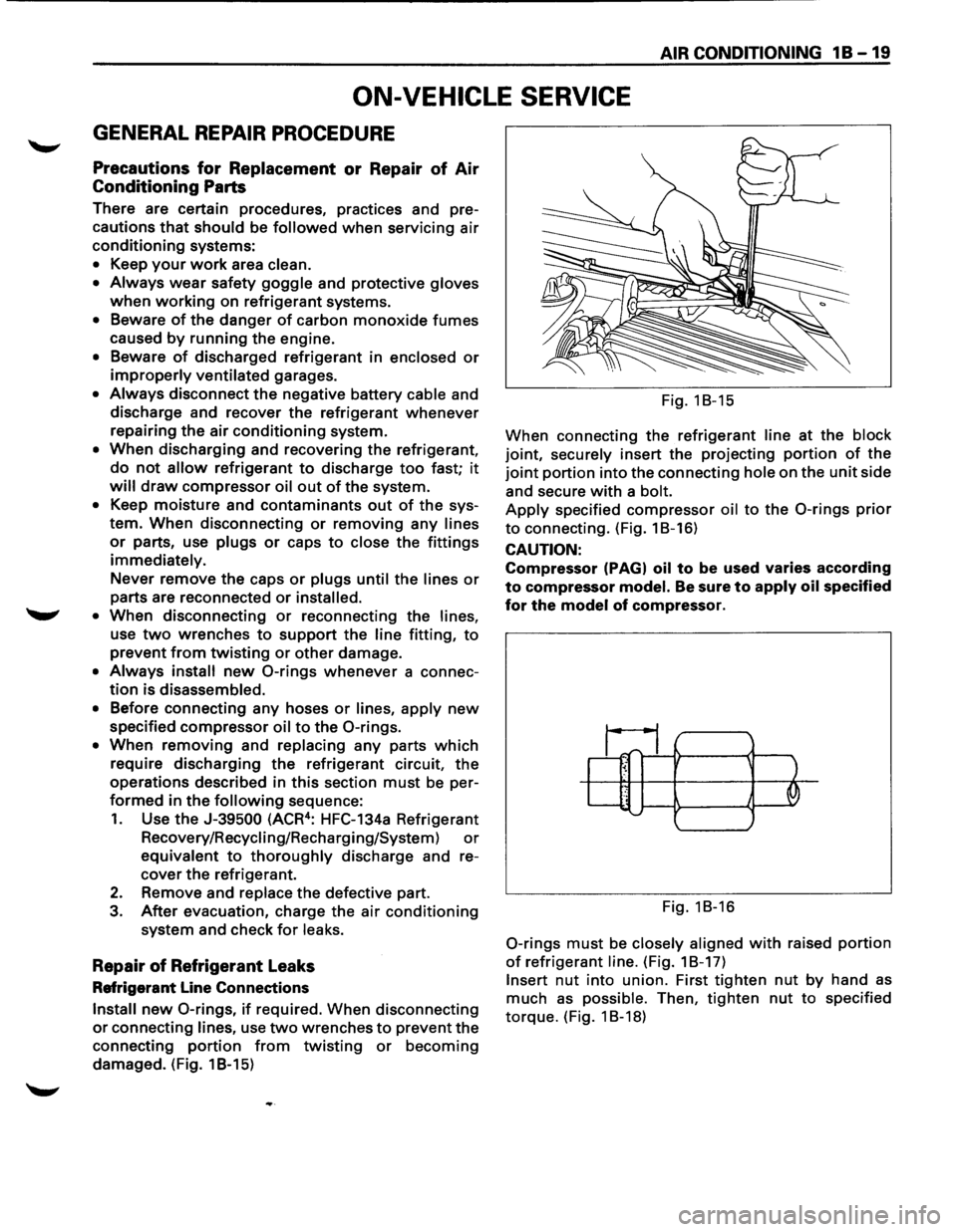
Install new 0-rings, if required. When disconnecting
or connecting lines, use two wrenches to prevent the
connecting
portion from twisting or becoming
damaged. (Fig. 1 B-15) Fig.
18-15
When connecting the refrigerant
line at the block
joint, securely insert the projecting portion of the
joint portion into the connecting hole on the unit side
and secure
with a bolt.
Apply specified compressor oil to the 0-rings prior
to connecting. (Fig. 18-16)
CAUTION:
Compressor (PAGI oil to be used varies according
to compressor model. Be sure to apply oil specified
for the model of compressor.
~1;1_ ~ ' .. J '--......
Fig. 18-16
0-rings must be closely aligned with raised portion
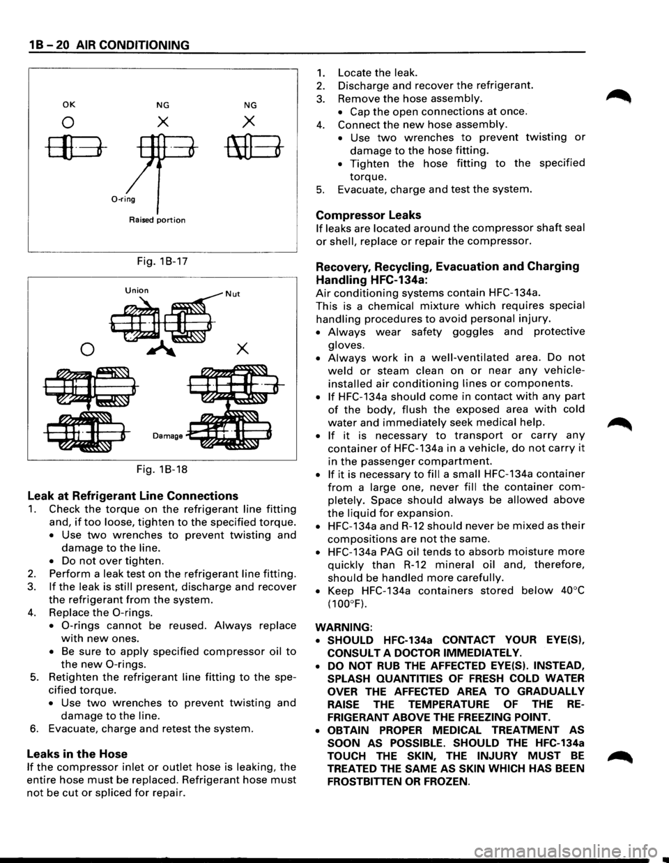
of refrigerant line. (Fig. 18-17)
Insert nut into union. First tighten nut by hand as
much as possible. Then, tighten nut to specified
torque. (Fig. 1 8-18)
Page 74 of 1928
1 B -20 AIR CONDITIONING
OK NG NG
0 X X
ffB-mEt
0-ring
Raised portion
Fig. 18-17
0
Fig. 18-18
Leak at Refrigerant Line Connections
1. Check the torque on the refrigerant line fitting
and, if too loose, tighten to the specified torque.
• Use two wrenches to prevent twisting and
damage to the line.
•
Do not over tighten.
2. Perform a leak test on the refrigerant line fitting.
3. If the leak is still present, discharge and recover
the refrigerant from the system.
4. Replace the 0-rings.
• 0-rings cannot be reused. Always replace
with new ones.
• Be sure to apply specified compressor oil to
the new 0-rings.
5. Retighten the refrigerant line fitting to the spe
cified torque.
• Use two wrenches to prevent twisting and
damage to the line.
6. Evacuate, charge and retest the system.
Leaks in the Hose
If the compressor inlet or outlet hose is leaking, the
entire hose must be replaced. Refrigerant hose must
not be cut or spliced for repair.
1.
2.
3.
4.
5.
Locate the leak.
Discharge and recover the refrigerant.
Remove
the hose assembly.
• Cap the open connections at once.
Connect
the new hose assembly.
•
Use two wrenches to prevent twisting or
damage to the hose fitting.
• Tighten the hose fitting to the specified
torque.
Evacuate, charge and test the system.
Compressor Leaks
If leaks are located around the compressor shaft seal
or shell, replace or repair the compressor.
Recovery, Recycling, Evacuation and Charging
Handling HFC-134a:
Air conditioning systems contain HFC-134a.
This is a chemical mixture which requires special
handling procedures to avoid personal injury.
• Always wear safety goggles and protective
gloves.
•
Always work in a well-ventilated area. Do not
weld or steam clean on or near any vehicle
installed air conditioning lines or components.
• If HFC-134a should come in contact with any part
of the body, flush the exposed area with cold
water and immediately seek medical help.
•
If it is necessary to transport or carry any
container of HFC-134a in a vehicle, do not carry it
in the passenger compartment.
• If it is necessary to fill a small HFC-134a container
from a large one, never fill the container com
pletely. Space should always be allowed above
the liquid for expansion.
• HFC-134a and R-12 should never be mixed as their
compositions are not the same.
• HFC-134a PAG oil tends to absorb moisture more
quickly than R-12 mineral oil and, therefore,
should be handled more carefully.
•
Keep HFC-134a containers stored below 40°C
(100°F).
WARNING: • SHOULD
HFC-134a CONTACT YOUR EYE(S),
CONSULT
A DOCTOR IMMEDIATELY.
•
DO NOT RUB THE AFFECTED EYE(S). INSTEAD,
SPLASH QUANTITIES
OF FRESH COLD WATER
OVER THE AFFECTED AREA TO GRADUALLY
RAISE THE TEMPERATURE OF THE RE
FRIGERANT ABOVE THE FREEZING POINT.
• OBTAIN
PROPER MEDICAL TREATMENT AS
SOON
AS POSSIBLE. SHOULD THE HFC-134a
TOUCH THE SKIN, THE INJURY MUST BE
TREATED THE SAME AS SKIN WHICH HAS BEEN
FROSTBITTEN OR FROZEN.
Page 79 of 1928
5. Refrigerant line connector
• When removing the line connector, the con
necting part
should immediately be plugged
or capped to prevent foreign matter from
being mixed into the line.
6. Compressor
l••liNSTALLATION
6. Compressor
• Tighten the compressor fixing bolts to the
specified torque.
~~~ Torque N·m (lb·ft) 19 (14)
5. Refrigerant line connector
• Tighten the refrigerant line connector fixing
bolts to the specified torque.
~~~ Torque N·m (lb.ft) 15 (11)
• 0-rings cannot be reused. Always replace
with new ones.
1~1 • Be sure to apply new compressor oil to the 0-
rings when connecting refrigerant lines.
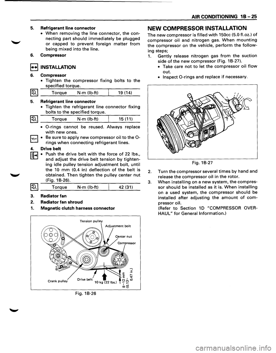
4. Drive belt
r:cJ • Push the drive belt with the force of 22 lbs.,
L:D and adjust the drive belt tension by tighten-
ing idle pulley tension adjustment bolt, until
the 10 mm (0.4 in) deflection of the belt is
obtained. Then
tighten the pulley center nut
(Fig. 1 B-26).
~~I __ T_o_r_!q_ue.:...._ __ N_·m__;_(l_b_·ft....:..) _ __,_ __ 4_2....:..(_31_)_
3. Radiator fan
2. Radiator fan shroud
1. Magnetic clutch harness connector
Tension pulley
Crank pulley 10 kg (22 lbs.)
Fig. 18-26
AIR CONDITIONING 1 B -25
NEW COMPRESSOR INSTALLATION
The new compressor is filled with 150cc (5.0 fl.oz.) of
compressor oil and nitrogen gas. When mounting
the compressor on the vehicle, perform the follow
ing steps;
1. Gently release nitrogen gas from the suction
side
ofthe new compressor (Fig. 18-27).
• Take care not to let the compressor oil flow
out.
• Inspect 0-rings and replace if necessary.
Fig. 18-27
2. Turn the compressor several times by hand and
release
the compressor oil in the rotor.
3. When installing on a new system, the compres
sor should be installed as it is. When installing
on a used system, the compressor should be
installed after adjusting the amount of com
pressor oil.
(Refer to Section 10 "COMPRESSOR OVER
HAUL" for General Information.)
Page 80 of 1928
1 B -26 AIR CONDITIONING
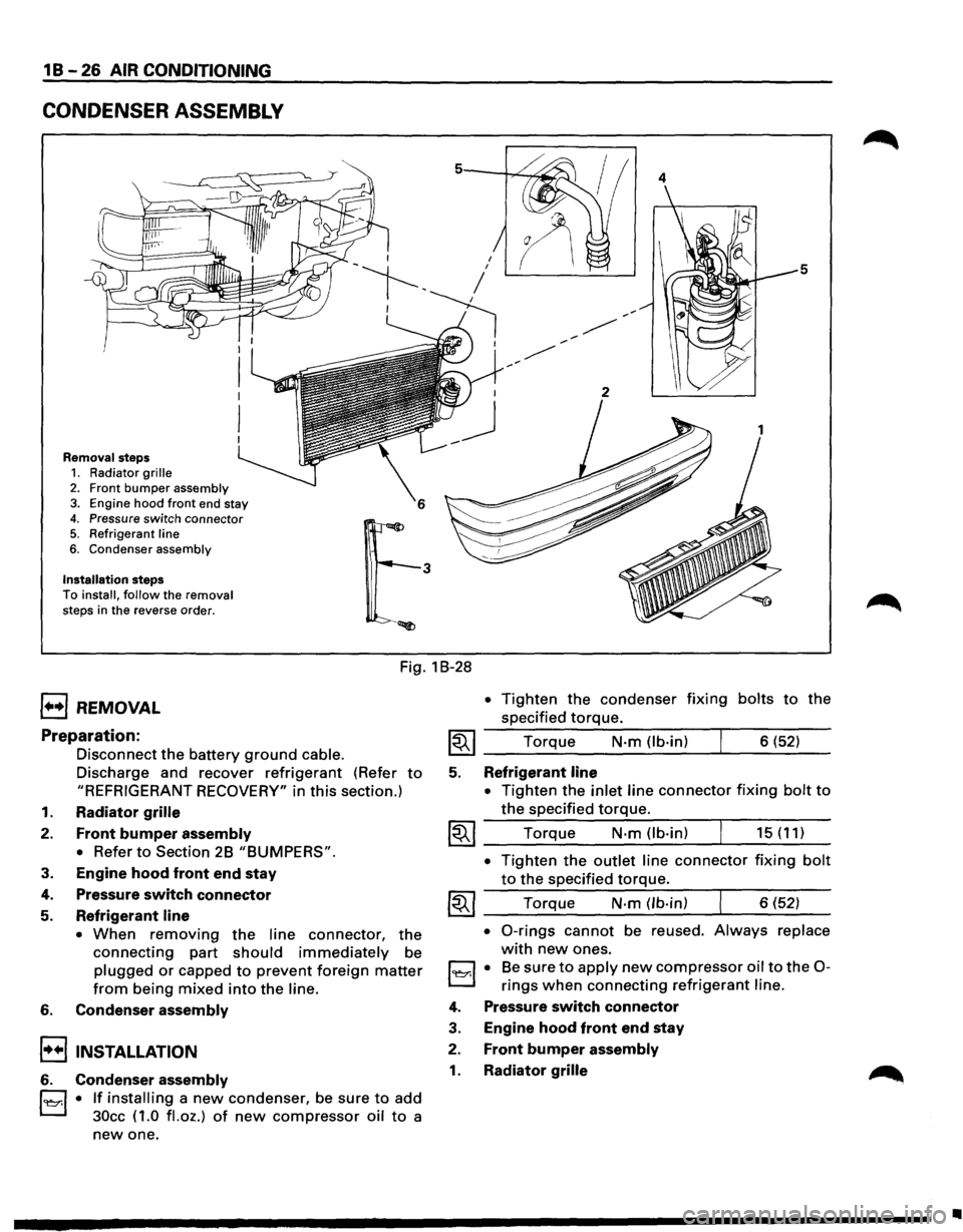
CONDENSER ASSEMBLY
Removal steps 1. Radiator grille
2. Front bumper assembly 3. Engine hood front end stay
4. Pressure switch connector 5. Refrigerant line
6. Condenser assembly
Installation steps To install, follow the removal
steps in the reverse order.
4
5
Fig. 1 B-28
1••1 REMOVAL
Preparation:
Disconnect the battery ground cable.
Discharge and recover refrigerant (Refer to
"REFRIGERANT RECOVERY" in this section.)
1. Radiator grille
2. Front bumper assembly
•
Refer to Section 2B "BUMPERS".
3. Engine hood front end stay
4. Pressure switch connector
5. Refrigerant line
• When removing the line connector, the
connecting part should immediately be
plugged or capped to prevent foreign matter
from being mixed into the line.
6. Condenser assembly
!••I INSTALLATION
6. Condenser assembly
l'l::r.l • If installing a new condenser, be sure to add
30cc ( 1.0
fl. oz.) of new compressor oil to a
new one.
• Tighten the condenser fixing bolts to the
specified
torque.
~~~ Torque N·m (lb-in) 6 (52)
5. Refrigerant line
•
Tighten the inlet line connector fixing bolt to
the specified torque.
~~~ Torque N·m (lb-in) 15 (11)
• Tighten the outlet line connector fixing bolt
to the specified torque.
~~~ Torque N-m (lb-in) 6 (52)
• 0-rings cannot be reused. Always replace
with new ones.
l'l::r.l • Be sure to apply new compressor oil to the 0-
rings when connecting refrigerant line.
4. Pressure switch connector
3. Engine hood front end stay
2. Front bumper assembly
1. Radiator grille
•
Page 81 of 1928
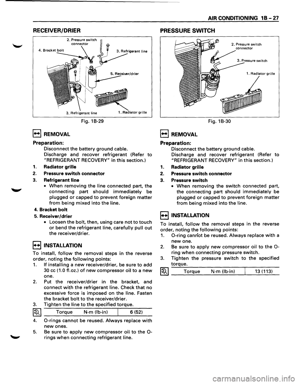
RECEIVER/DRIER
2. Pressure switch
3. Refrigerant
line
1••1 REMOVAL
Preparation:
Fig. 1 B-29
1. Radiator grille
Disconnect the battery ground cable.
Discharge and recover refrigerant (Refer to
"REFRIGERANT RECOVERY" in this section.)
1. Radiator grille
2. Pressure switch connector
3. Refrigerant line
•
When removing the line connected part, the
connecting part
should immediately be
plugged or capped to prevent foreign matter
from being mixed into the line.
4. Bracket bolt
5. Receiver/drier
• Loosen the bolt, then, using care not to touch
or bend the refrigerant line, carefully pull out
the receiver/drier.
I••I•NSTALLATION
To install, follow the removal steps in the reverse
order,
noting the following points:
1. If installing a new receiver/drier, be sure to add
30 cc ( 1.0 fl. oz.) of new compressor oil to a new
one.
2. Put the receiver/drier in the bracket, and
connect
with the refrigerant line. Check that no
excessive force is imposed on the line. Fasten
the bracket
bolt to the receiver/drier.
3. Tighten the line to the specified torque.
~~~ Torque N-m (lb-in) I 6 (52)
4. 0-rings cannot be reused. Always replace with
new ones.
5. Be sure to apply new compressor oil to the 0-
rings when connecting refrigerant line.
AIR CONDITIONING 1 B -27
PRESSURE SWITCH
1••1 REMOVAL
Preparation:
Fig. 18-30
2. Pressure switch
1.
Radiator grille
Disconnect the battery ground cable.
Discharge and recover refrigerant (Refer to
"REFRIGERANT RECOVERY" in this section.)
1. Radiator grille
2. Pressure switch connector
3. Pressure switch
• When removing the switch connected part,
the connecting
part should immediately be
plugged or capped to prevent foreign matter
from being mixed into the line.
I••IINSTALLATION
To install, follow the removal steps in the reverse
order,
noting the following points:
1. 0-ring canriot be reused. Always replace with a
new one.
2. Be sure to apply new compressor oil to the 0-
ring when connecting pressure switch.
3. Tighten the pressure switch to the specified
torque.
~~~ Torque N·m (lb-in) 13 (113)
Page 83 of 1928
I••IINSTALLATION
To install, follow the removal steps in the reverse
order,
noting the following points:
1. To install a new evaporator assembly, add 50cc
(1.7 fl.oz.) of new compressor oil to a new core.
2. Tighten the refrigerant outlet line to the
specified torque.
~~~ Torque N·m (lb.ft) 25 (18)
AIR CONDITIONING 1 B-29
3. Tighten the refrigerant inlet line to the specified
torque.
~~~ Torque N·m (lb·ft) 15 (11)
4. 0-rings cannot be reused. Always replace with
new ones.
5. Be sure to apply new compressor oil to the 0-
rings when connecting lines.
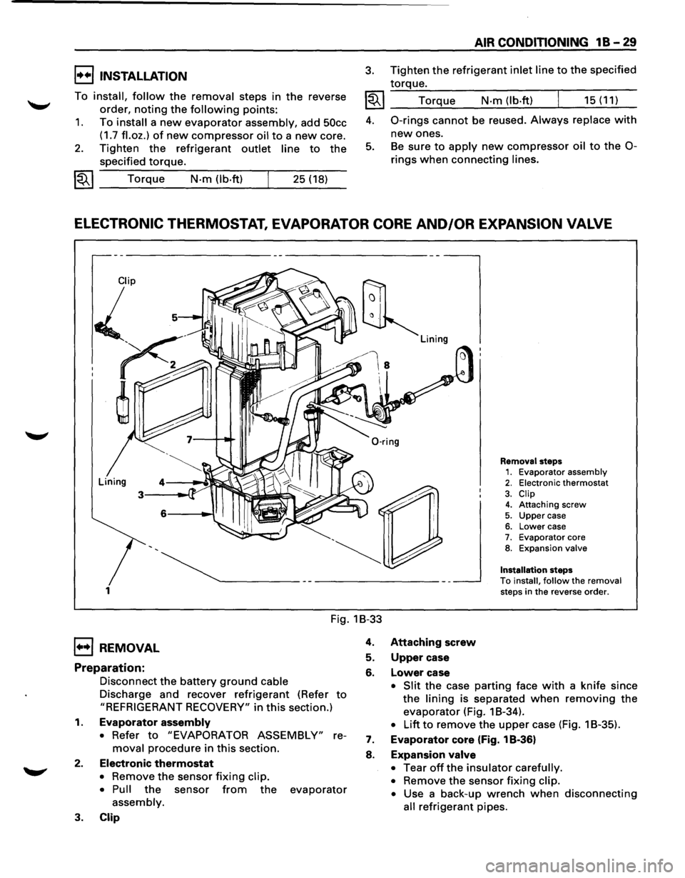
ELECTRONIC THERMOSTAT, EVAPORATOR CORE AND/OR EXPANSION VALVE
1
Removal steps 1. Evaporator assembly 2. Electronic thermostat
3. Clip 4. Attaching screw
5. Upper case 6. Lower case 7. Evaporator core 8. Expansion valve
Installation
steps
To install, follow the removal steps in the reverse order.
Fig. 1B-33
1••1 REMOVAL
Preparation:
Disconnect the battery ground cable
Discharge and recover refrigerant (Refer to
"REFRIGERANT RECOVERY" in this section.)
1. Evaporator assembly
• Refer to "EVAPORATOR ASSEMBLY" re
moval procedure in this section.
2. Electronic thermostat
• Remove the sensor fixing clip.
• Pull
the sensor from the evaporator
assembly.
3. Clip
4. Attaching screw
5. Upper case
6. Lower case
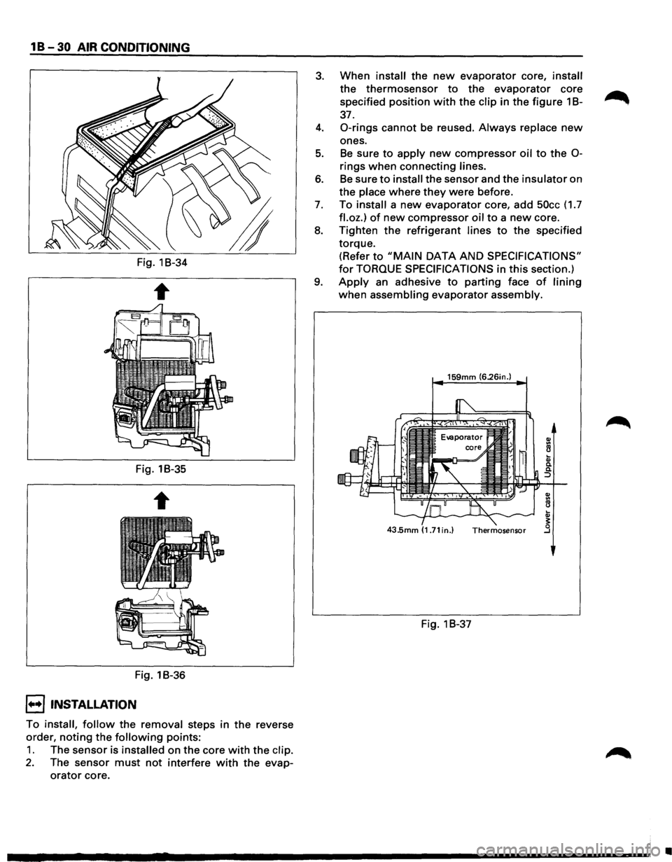
• Slit the case parting face with a knife since
the lining is separated when removing the
evaporator (Fig. 1 B-34).
• Lift to remove the upper case (Fig. 1 B-35).
7. Evaporator core (Fig. 1 B-36)
8. Expansion valve
•
Tear off the insulator carefully.
•
Remove the sensor fixing clip.
•
Use a back-up wrench when disconnecting
all refrigerant pipes.
Page 84 of 1928
1 B -30 AIR CONDITIONING
Fig. 1B-34
Fig. 1B-35
Fig. 1B-36
I••! INSTALLATION
To install, follow the removal steps in the reverse
order,
noting the following points:
1. The sensor is installed on the core with the clip.
2. The sensor must not interfere with the evap
orator core.
3. When install the new evaporator core, install
the thermosensor to the evaporator core
specified position
with the clip in the figure 1 B-~
37.
4. 0-rings cannot be reused. Always replace new
ones.
5. Be sure to apply new compressor oil to the 0-
rings when connecting lines.
6. Be sure to install the sensor and the insulator on
the place where
they were before.
7. To install a new evaporator core, add 50cc (1.7
fl.oz.) of new compressor oil to a new core.
8. Tighten the refrigerant lines to the specified
torque. (Refer
to "MAIN DATA AND SPECIFICATIONS"
for TORQUE SPECIFICATIONS in this section.)
9. Apply an adhesive to parting face of lining
when assembling evaporator assembly.
159mm (6.26in.)
Fig. 1 B-37
•
Page 86 of 1928
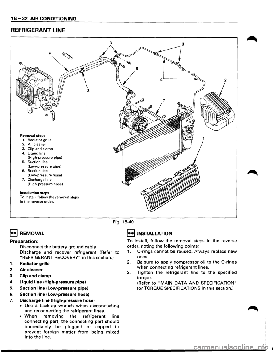
1 B -32 AIR CONDITIONING
REFRIGERANT LINE
5
Removal steps
1. Radiator grille 2. Air cleaner
3. Clip and clamp 4. Liquid line
(High-pressure pipe)
5. Suction line (Low-pressure pipe)
6. Suction line (Low-pressure hose) 7. Discharge line (High-pressure hose)
Installation steps To install, follow the removal steps
in the reverse order.
3 3
1++1 REMOVAL
Fig. 18-40
I••IINSTALLATION
Preparation:
Disconnect the battery ground cable
Discharge and recover
refrigerant (Refer to
"REFRIGERANT RECOVERY" in this section.)
1. Radiator grille
2. Air cleaner
3. Clip and clamp
4. Liquid line (High-pressure pipe)
5. Suction line (Low-pressure pipe)
6. Suction line (low-pressure hose)
7. Discharge line (High-pressure hose)
• Use a back-up wrench when disconnecting
and reconnecting the refrigerant lines.
• When removing the refrigerant line
connecting part, the connecting part should
immediately be plugged or capped to
prevent foreign matter from being mixed
into the line. To
install,
follow the removal steps in the reverse
order,
noting the following points:
1. 0-rings cannot be reused. Always replace new
ones.
2. Be sure to apply compressor oil to the 0-rings
when connecting refrigerant lines.
3. Tighten the refrigerant line to the specified
torque.
(Refer to "MAIN DATA AND SPECIFICATION"
for TORQUE SPECIFICATIONS in this section.)
•
Page 88 of 1928
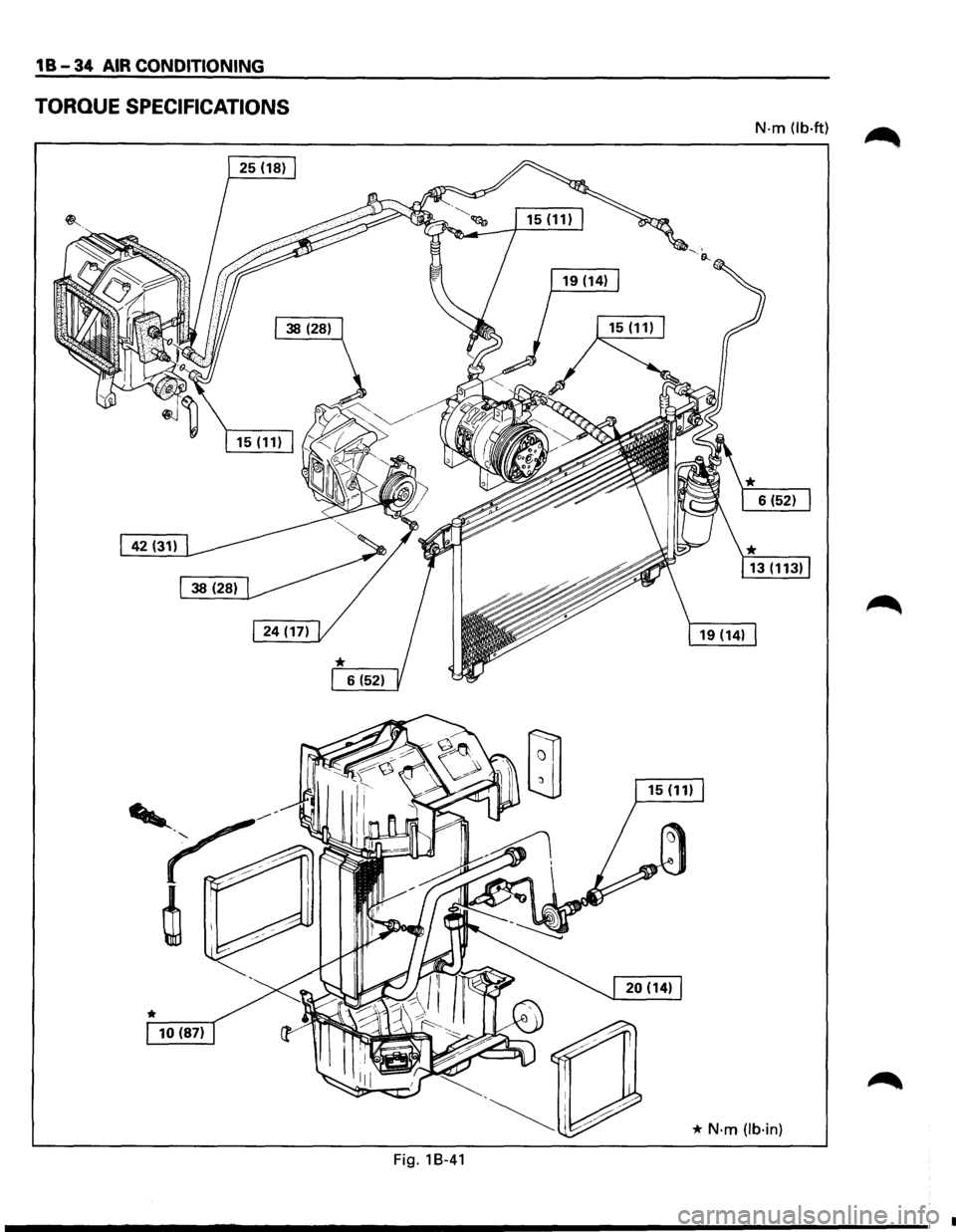
1 B-34 AIR CONDITIONING
TORQUE SPECIFICATIONS
N-m (lb·ft)
* N·m (lb·in)
Fig. 18-41
_____________ ,.
Page 89 of 1928
COMPRESSOR OVERHAUL 1 D - 1
SECTION 10
COMPRESSOR OVERHAUL
CONTENTS
General Description . . . . . . . . . . . . . . . . . . . . . 1 D-1
Diagnosis . . . . . . . . . . . . . . . . . . . . . . . . . . . . . 1
D-2
General Information . . . . . . . . . . . . . . . . . . . . 1 D-3
Compressor Oil . . . . . . . . . . . . . . . . . . . . . . 1 D-3
Service Procedures . . . . . . . . . . . . . . . . . . . . . 1D-5
Magnetic Clutch Assembly . . . . . . . . . . . . . 1 D-5
Main Data and Specifications . . . . . . . . . . . . . 1 D-8
General Specifications . . . . . . . . . . . . . . . . . 1 D-8
Torque Specifications . . . . . . . . . . . . . . . . . 1 D-8
Special Tools . . . . . . . . . . . . . . . . . . . . . . . . . . 1D-9
GENERAL DESCRIPTION
When servicing the compressor, keep dirt or foreign
material from getting on or into the compressor
parts and system. Clean tools and a clean work area
are
important for proper service. The compressor
connections and the outside of the compressor
should be cleaned before any "On-Vehicle" repair,
or before removal of the compressor. The parts must
be kept clean at all times and any parts to be
reassembled
should be cleaned with Trichloro
ethane, naphtha, kerosene, or equivalent solvent,
and
dried with dry air. Use only lint free cloths to
wipe parts.
The
operations described below are based on bench
overhaul
with compressor removed from the
vehicle, except as noted. They have been prepared
in
order of accessibility of the components. When
the compressor is removed from the vehicle for
servicing, the oil remaining in the compressor
should be discarded and new compressor oil added
to the compressor.
Magnetic clutch assembly repair procedures require
that the system be discharged of refrigerant. (Refer
to Section 1 B for "REFRIGERANT RECOVERY".)
Compressor malfunction will appear in one of four
ways: noise, seizure, leakage or low discharge
pressure. Resonant
compressor noises are not
cause for alarm; however, irregular noise or rattles
may indicate broken parts or excessive clearances
due to wear. To check seizure, de-energize the
magnetic clutch and check to see if the drive plate
can be rotated.
If rotation is impossible, the com
pressor is seized. Low discharge pressure may be
due to a faulty internal seal of the compressor, or a
restriction in the compressor.
Low discharge pres
sure
may also be due to an insufficient refrigerant
charge
or a restriction elsewhere in the system.
These possibilities
should be checked prior to
servicing the compressor. If the compressor is
inoperative,
but is not seized, check to see if current
is being supplied to the magnetic clutch coil
terminals.
This vehicle is equipped with five-vane rotary com
pressor.
The
compressor has vanes built into a rotor which is
mounted on a shaft.
When the shaft rotates, the vanes built into the
cylinder block assembly are opened by centrifugal
force.
This changes the volume of the space formed by the
rotor and cylinder, resulting in the intake and
compression of the refrigerant gas. The discharge
valve and the
valve stopper, which protects the
discharge valve, are
built into the cylinder block
assembly. There is no suction valve but a shaft seal
is
installed between the shaft and head; a trigger
valve, which applies back pressure to the vanes, is
installed in the cylinder block and a refrigerant gas
temperature sensor is installed in the front head.
The specified
quantity of compressor oil is contained
in
the compressor to lubricate the various parts
using
the refrigerant gas discharge pressure.
The thermo sensor is installed to the front head of
the compressor to protect it by stopping its
operation when the refrigerant gas is insufficient or
when the temperature get abnormally high.
•OFF ..... 160 ±soc (320.0 ± 9.0°F)
•ON ..... 135 ±soc (275.0 ± 9.0°F)
The oil used in the HFC-134a system compressor
differs from that used in R-12 systems.
Also, compressor
oil to be used varies according to
the compressor model. Be sure to avoid mixing two
or more different types of oil.
If the wrong oil is used, lubrication will be poor and
the compressor will seize or malfunction.
The specified
amount of the compressor oil is
150cc (5.0 fl.oz.).