wiring ISUZU TROOPER 1995 User Guide
[x] Cancel search | Manufacturer: ISUZU, Model Year: 1995, Model line: TROOPER, Model: ISUZU TROOPER 1995Pages: 1928
Page 224 of 1928
3F4-14 SUPPLEMENTAL RESTRAINT SYSTEM (SRS) STEERING WHEEL & COLUMN
EJREMOVAL
Preparation: • Turn the steering wheel so that the
vehicle's
wheels are pointing straight
ahead.
• Turn the ignition switch to "LOCK".
•
Disconnect the battery "-" terminal
cable,
and wait at least 5 minutes.
• Disconnect the yellow 3way SRS
connector located under the steering
column.
wcAUTION:
The wheel of the vehicle must be straight ahead
and the steering
column in the "LOCK• position
before disconnecting the steering
column from
the steering gear.
Failure to do so will cause the SRS coil assembly
to become uncentered which will cause damage
to the SRS coil assembly.
1. Front console assembly
• Disconnect the transmission (for MfT) and
transfer
control lever knob.
• Disconnect the wiring harness connectors.
2. Steering lower cover
• Remove the engine hood opening lever.
3. Driver knee bolster (reinforcement)
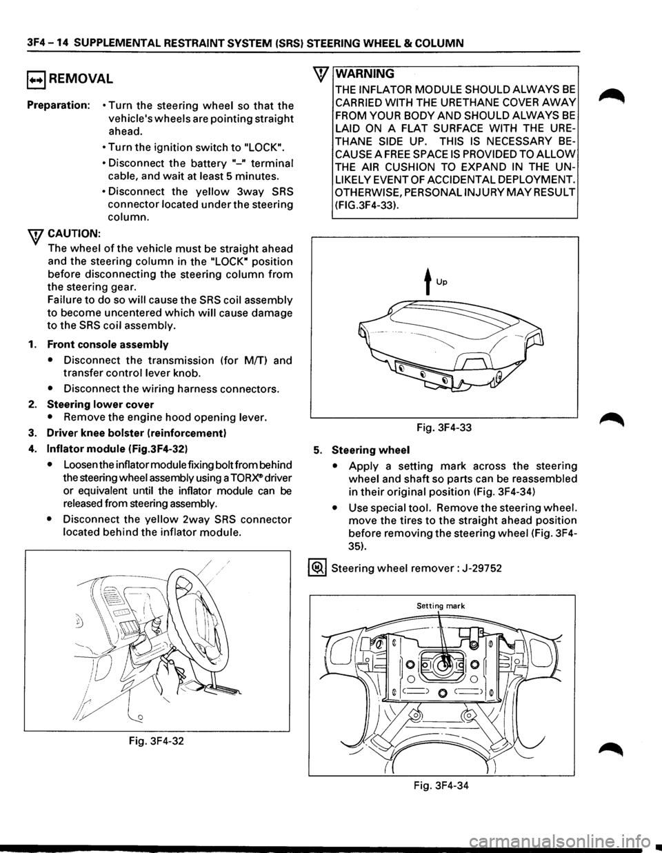
4. Inflator module (Fig.3F4-32)
• Loosen the inflator module fixing bolt from behind
the steering
wheel assembly using a TORX® driver
or
equivalent until the inflator module can be
released from steering assembly.
•
Disconnect the yellow 2way SRS connector
located behind the inflator module.
Fig. 3F4-32
\V WARNING
THE INFLATOR MODULE SHOULD ALWAYS BE
CARRIED WITH THE URETHANE COVER AWAY
FROM YOUR BODY AND SHOULD ALWAYS BE
LAID ON A FLAT SURFACE WITH THE URE
THANE SIDE UP. THIS IS NECESSARY BE
CAUSE A FREE SPACE IS PROVIDED TO ALLOW
THE AIR CUSHION TO EXPAND IN THE UN
LIKELY EVENT OF ACCIDENTAL DEPLOYMENT.
OTHERWISE, PERSONALINJURYMAYRESULT
(FIG.3F4-33).
Fig. 3F4-33
5. Steering wheel
• Apply a setting mark across the steering
wheel and shaft so parts can be reassembled
in their original position (Fig. 3F4-34)
• Use special tool. Remove the steering wheel.
move the tires to the straight ahead position
before removing the steering
wheel (Fig. 3F4-
35).
1®.1 Steering wheel remover: J-29752
Setting mark
Fig. 3F4-34
..
Page 225 of 1928
SUPPLEMENTAL RESTRAINT SYSTEM (SRS) STEERING WHEEL & COLUMN 3F4-15
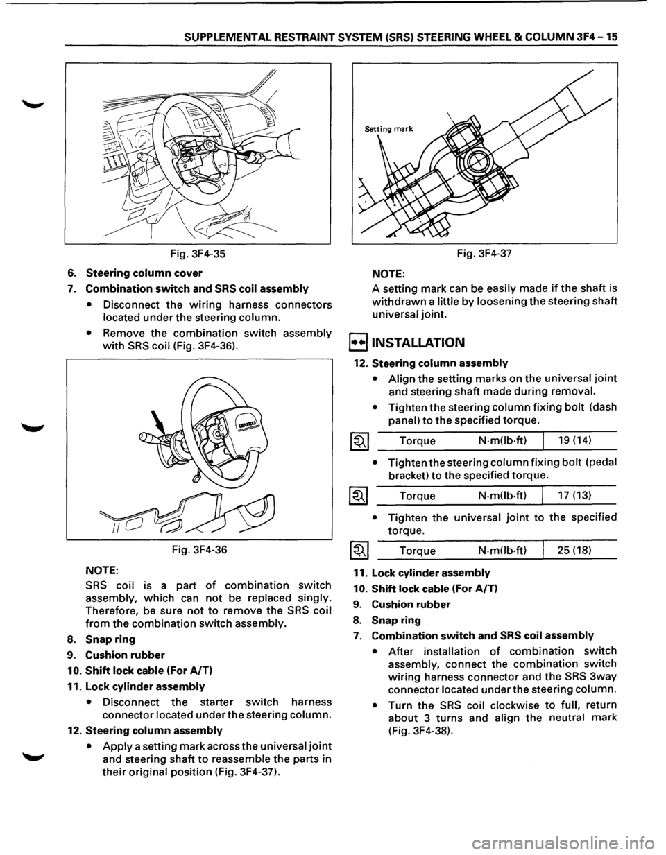
Fig. 3F4-35
6. Steering column cover
7. Combination switch and SRS coil assembly
•
Disconnect the wiring harness connectors
located under the steering column.
• Remove the combination switch assembly
with SRS coil (Fig. 3F4-36).
Fig. 3F4-36
NOTE:
SRS coil is a part of combination switch
assembly, which can not be replaced singly.
Therefore, be sure not to remove the SRS coil
from the combination switch assembly.
8. Snap ring
9. Cushion rubber
10. Shift lock cable (For A/T)
11. Lock
cylinder assembly
• Disconnect the starter switch harness
connector located under the steering column.
12. Steering column assembly
•
Apply a setting mark across the universal joint
and steering shaft to reassemble the parts in
their original position (Fig. 3F4-37). Fig.
3F4-37
NOTE:
A setting mark can be easily made if the shaft is
withdrawn a little by loosening the steering shaft
universal joint.
B INSTALLATION
12. Steering column assembly
• Align the setting marks on the universal joint
and steering shaft made during removal.
•
Tighten the steering column fixing bolt (dash
panel) to the specified torque.
Torque
N-mOb·ft) 19 (14)
• Tighten the steering column fixing bolt (pedal
bracket) to the specified torque.
Torque N·m(lb·ft) 17 (13)
• Tighten the universal joint to the specified
torque.
Torque
N-m(lb·ft)
11. Lock cylinder assembly
10.
Shift lock cable (For A/T)
9. Cushion rubber
8. Snap ring
25 (18)
7. Combination switch and SRS coil assembly
• After installation of combination switch
assembly, connect the combination switch
wiring harness connector and the SRS 3way
connector located under the steering column.
•
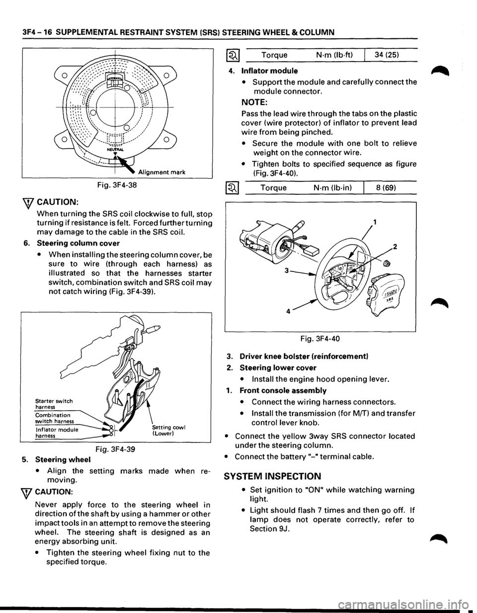
Turn the SRS coil clockwise to full, return
about 3 turns and align the neutral mark
(Fig. 3F4-38).
Page 226 of 1928
3F4-16 SUPPLEMENTAL RESTRAINT SYSTEM (SRS) STEERING WHEEL & COLUMN
Alignment mark
Fig. 3F4-38
\fCAUTION:
When turning the SRS coil clockwise to full, stop
turning if resistance is felt. Forced furtherturning
may damage to the cable in the SRS coil.
6. Steering column cover
• When installing the steering column cover, be
sure
to wire (through each harness) as
illustrated so that the harnesses starter
switch,
combination switch and SRS coil may
not catch wiring (Fig. 3F4-39).
Starter switch
harness
Combination switch harness
Inflator module harness
5. Steering wheel
Fig. 3F4-39
• Align the setting marks made when re
moving.
WCAUTION:
Never apply force to the steering wheel in
direction
ofthe shaft by using a hammer or other
impacttools in an attempt to remove the steering
wheel. The steering
shaft is designed as an
energy absorbing unit.
• Tighten the steering wheel fixing nut to the
specified torque. Torque
N·m (lb·ftl 34
(25)
4. Inflator module
• Support the module and carefully connect the
module connector.
NOTE:
Pass the lead wire through the tabs on the plastic
cover (wire protector) of inflator to prevent lead
wire from being pinched.
• Secure the module with one bolt to relieve
weight on the connector wire.
• Tighten bolts to specified sequence as figure
(Fig. 3F4-40).
Torque
N·m (lb-in) 8 (69)
Fig. 3F4-40
3. Driver knee bolster (reinforcement)
2. Steering lower cover
• Install the engine hood opening lever.
1. Front console assembly
• Connect the wiring harness connectors.
• Install the transmission (for M/T) and transfer
control lever knob.
• Connect the yellow 3way SRS connector located
under the steering column.
• Connect the battery "-"terminal cable.
SYSTEM INSPECTION
• Set ignition to "ON" while watching warning
light.
• Light should flash 7 times and then go off. If
lamp does not operate correctly, refer to
Section 9J.
•
Page 385 of 1928
REAR WHEEL ANTILOCK BRAKE SYSTEM 5A3-17
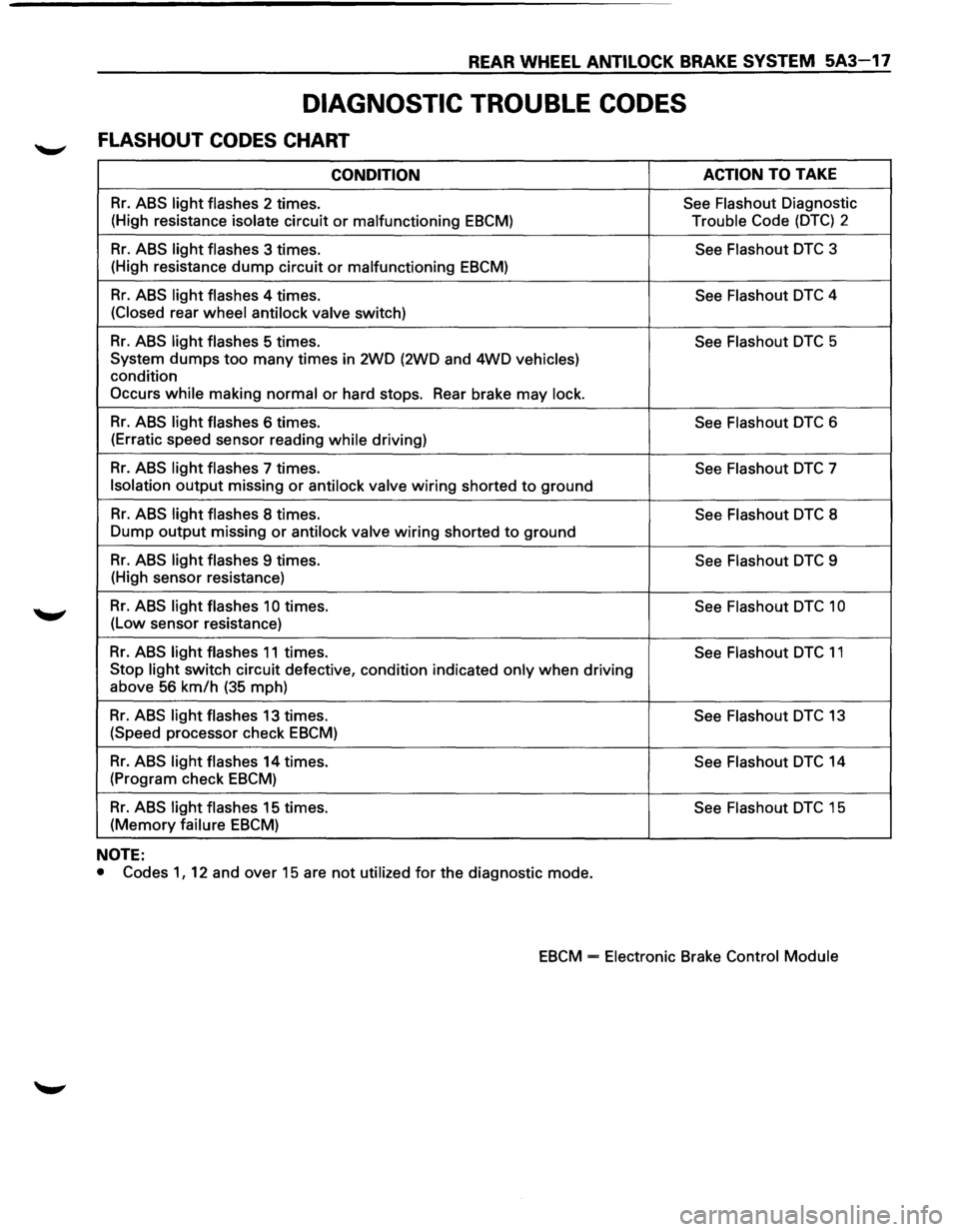
DIAGNOSTIC TROUBLE CODES
FLASHOUT CODES CHART
CONDITION ACTION TO
TAKE
Rr. ABS light flashes 2 times. See Flashout Diagnostic
(High resistance
isolate circuit or malfunctioning EBCM) Trouble Code (DTC) 2
Rr. ABS light flashes 3 times. See Flashout DTC 3
(High resistance
dump circuit or malfunctioning EBCM)
Rr. ABS light flashes 4 times.
See Flashout DTC 4
(Closed rear wheel antilock valve switch)
Rr. ABS light flashes 5 times.
See Flashout DTC 5
System dumps
too many times in 2WD (2WD and 4WD vehicles)
condition
Occurs while making normal or hard stops. Rear brake may lock.
Rr. ABS light flashes 6 times.
See Flashout DTC 6
(Erratic speed sensor reading
while driving)
Rr. ABS light flashes 7 times. See Flashout DTC 7
Isolation output missing or antilock valve wiring shorted to ground
Rr. ABS light flashes 8 times.
See Flashout DTC 8
Dump
output missing or antilock valve wiring shorted to ground
Rr. ABS light flashes 9 times. See Flashout DTC 9
(High sensor resistance)
Rr. ABS light flashes 10 times.
See Flashout DTC 1 0
(Low sensor resistance)
Rr. ABS light flashes 11 times.
See Flashout DTC 11
Stop light switch circuit defective, condition indicated only when driving
above
56 km/h (35 mph)
Rr. ABS light flashes 13 times.
See Flashout DTC 13
(Speed processor check EBCM)
Rr. ABS light flashes 14 times.
See Flashout DTC 14
(Program check
EBCM)
Rr. ABS light flashes 15 times.
See Flashout DTC 15
(Memory failure EBCM)
NOTE:
• Codes 1, 12 and over 15 are not utilized for the diagnostic mode.
EBCM = Electronic Brake Control Module
Page 395 of 1928
REAR WHEEL ANTILOCK BRAKE SYSTEM 5A3-27
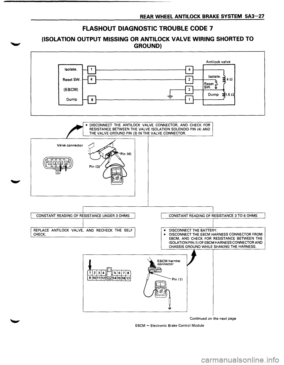
FLASHOUT DIAGNOSTIC TROUBLE CODE 7
(ISOLATION OUTPUT MISSING OR ANTI LOCK VALVE WIRING SHORTED TO
GROUND)
Anti lock valve
Isolate.
ResetSW. 40
(EBCM)
Dump
• DISCONNECT THE ANTILOCK VALVE CONNECTOR, AND CHECK FOR RESISTANCE BETWEEN THE VALVE ISOLATION SOLENOID PIN (4) AND
THE VALVE GROUND PIN (3) IN THE VALVE CONNECTOR.
Valve
connector
CONSTANT READING OF RESISTANCE UNDER 3 OHMS
REPLACE ANTILOCK VALVE, AND RECHECK THE SELF CHECK.
CONSTANT READING OF RESISTANCE 3 TO 6 OHMS
• DISCONNECT
THE BATTERY. • DISCONNECT THE EBCM HARNESS CONNECTOR FROM EBCM, AND CHECK FOR RESISTANCE BETWEEN THE ISOLATION PIN (1) OF EBCM HARNESS CONNECTOR AND CHASSIS GROUND WHILE SHAKING THE HARNESS.
Continued on the next page
EBCM
= Electronic Brake Control Module
Page 397 of 1928
REAR WHEEL ANTILOCK BRAKE SYSTEM 5A3-29
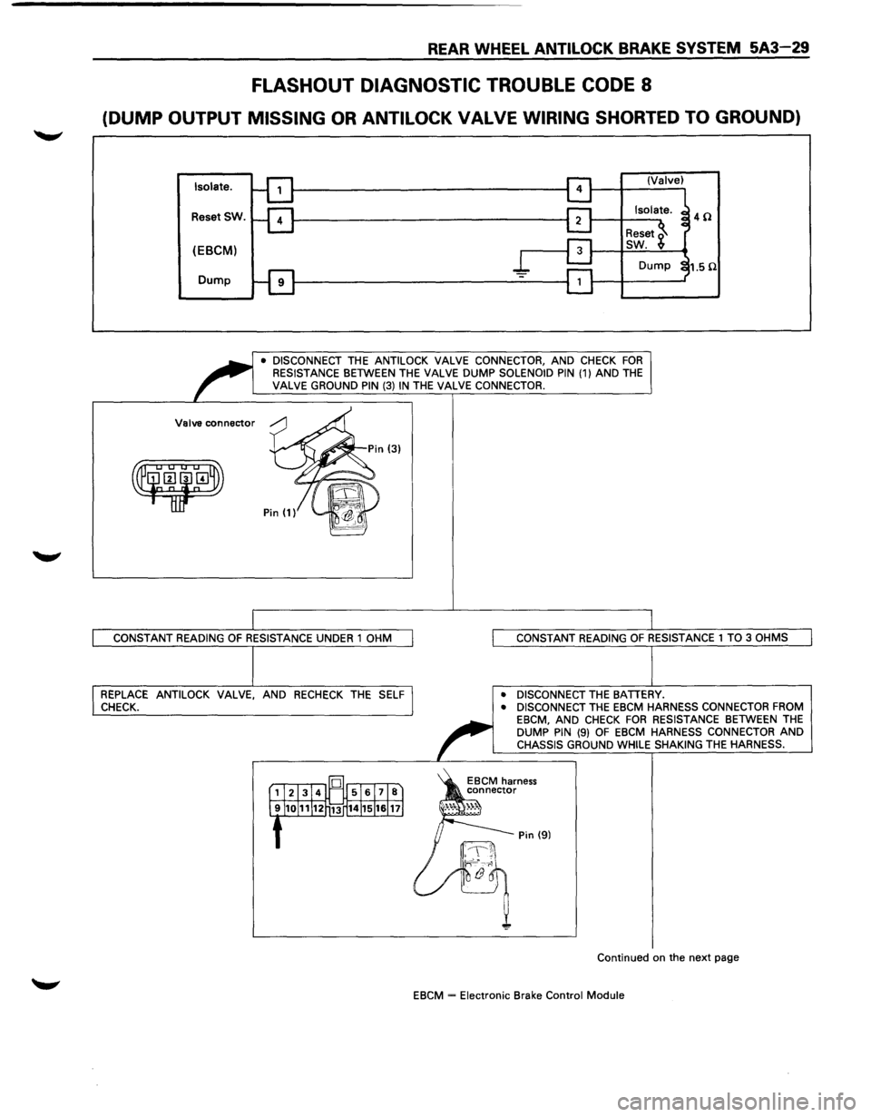
FLASHOUT DIAGNOSTIC TROUBLE CODE 8
(DUMP OUTPUT MISSING OR ANTILOCK VALVE WIRING SHORTED TO GROUND)
Isolate.
Reset SW.
(EBCM)
Dump
• DISCONNECT THE ANTILOCK VALVE CONNECTOR, AND CHECK FOR RESISTANCE BETWEEN THE VALVE DUMP SOLENOID PIN (1) AND THE VALVE GROUND PIN (3) IN THE VALVE CONNECTOR.
Valve
connector
CONSTANT READING OF RESISTANCE UNDER 1 OHM
REPLACE ANTILOCK VALVE, AND RECHECK THE SELF CHECK.
CONSTANT READING OF RESISTANCE 1 TO 3 OHMS
• DISCONNECT
THE BATIERY.
• DISCONNECT THE EBCM HARNESS CONNECTOR FROM EBCM, AND CHECK FOR RESISTANCE BETWEEN THE
DUMP PIN (9) OF EBCM HARNESS CONNECTOR AND CHASSIS GROUND WHILE SHAKING THE HARNESS.
Pin (9)
Continued on the
next page
EBCM
-Electronic Brake Control Module
Page 416 of 1928
5A4-6 4-WHEEL ANTILOCK BRAKE SYSTEM (ABS)
If only rear wheels are rotated using jacks or
drum tester, the system will diagnose a speed
sensor
malfunction and the "ABS" warning
light will illuminate. But actually no trouble
exists. After inspection stop the engine once
and re-start it,
then make sure that the "ABS"
warning light does not illuminate.
If the battery has been discharged
The engine may stall if the battery has been
completely discharged and the engine is started via
a
jumper cable. This is because the Antilock Brake
System (ABS) requires a
large quantity of
electricity. In this case, wait until the battery is
recharged,
or set the ABS to a non-operative state
by removing the fuse for the ABS (40A). After the
battery has been recharged, stop the engine and
install the ABS fuse. Start the engine again, and
confirm that the ABS warning light does not light.
NOTE ON INTERMITTENTS
As with virtually any electronic system, it is difficult
to identify an intermittent failure. In such a case
duplicating the system malfunction during a test
drive
or a good description of vehicle behavior from
the customer may be helpful in locating a "most
likely" failed component or circuit. The symptom
diagnosis chart may also be useful in isolating the
failure. Most intermittent problems are caused by
faulty electrical connections or wiring. When an
intermittent failure is encountered, check suspect
circuits for:
Suspected harness damage.
• Poor mating of connector halves or terminals
not fully seated in the connector body (backed
out).
Improperly formed or damaged terminals.
TEST DRIVING ABS COMPLAINT
VEHICLES
In case that there has been an abnormality in the
lighting pattern of "ABS" warning light, the fault
can be located in accordance with the "DIAGNOSIS
BY 'ABS' WARNING LIGHT ILLUMINATION
PATTERN". In case of such trouble as can be
detected
by the driver as a vehicle symptom,
however, it is necessary to give a test drive
following the test procedure mentioned below,
thereby reproducing the symptom for trouble
diagnosis on a symptom basis:
1. Start the engine and make sure that the "ABS"
W/L goes OFF. If the W/L remains ON, it
means that the Diagnostic Trouble Code (DTC)
is stored. Therefore, read the code and
locate
the fault.
2. Start the vehicle and accelerate to 30 km/h (19
mph) or more.
3. Slowly brake and stop the vehicle completely.
4. Then restart the vehicle and accelerate to 40
km/h (25 mph) or more.
5. Brake at a time so as to actuate the ABS and ... ~
stop the vehicle.
6. Be cautious of abnormality during the test. If
theW/Lis actuated while driving, read the DTC
and locate the fault.
7. If the abnormality is not reproduced by the
test, make best efforts
to reproduce the
situation reported
by the customer.
8. If the abnormality has been detected, repair in
accordance
with the "SYMPTOM DIAGNOSIS".
NOTE:
Be sure to give a test drive on a wide, even
road
with a small traffic.
If an abnormality is detected, be sure to
suspend the test and start
trouble diagnosis at
once.
II ABS" WARNING LIGHT
When ABS trouble occurs to actuate "ABS"
warning light, the trouble code corresponding to
the trouble is stored in the EBCM. Only ordinary
brake is available with ABS being unactuated. Even
when "ABS" warning light is actuated, if the starter
switch is set
ON after setting it OFF once, the EBCM
checks
up on the entire system and, if there is no
abnormality, judges ABS to work currently and the
warning light is lit normally even though the
trouble code is stored.
NOTE:
Illumination of the "ABS" warning light
indicates that antilock braking is no longer
available. Power assisted braking without
antilock control is still available.
NORMAL OPERATION
II ABS" WARNING LIGHT
When the ignition is first moved from "OFF" to
"RUN", the amber "ABS" warning light will turn
"ON". The "ABS" warning light will turn "ON"
during engine starting and will usually stay "ON"
for approximately three seconds after the ignition
switch is returned to the "ON" position. The
warning light should remain "OFF" at all other
times.
•
Page 440 of 1928
5A4-30 4-WHEEL ANTILOCK BRAKE SYSTEM (ABS)
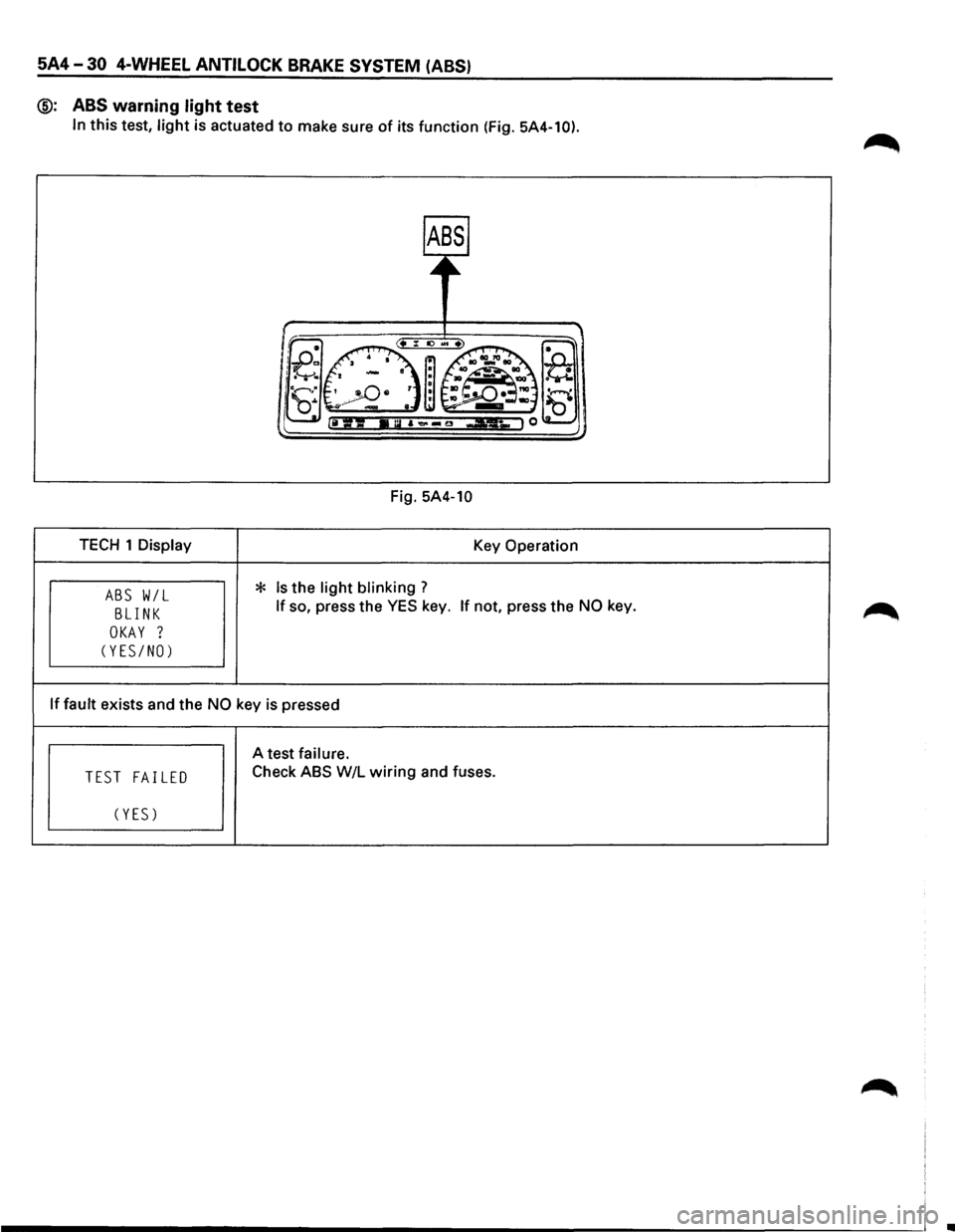
@: ABS
warning light test
In this test, light is actuated to make sure of its function (Fig. 5A4-10).
Fig. 5A4-10
TECH 1 Display
Key Operation
Is the light blinking ? ABS W/L * BLINK If so, press the YES key. If not, press the NO key.
OKAY ?
(YES/NO)
If
fault exists and the NO key is pressed
A test failure.
TEST FAILED Check ABS W/L wiring and
fuses.
(YES)
i _______________________________________________________________________ \
! •
Page 459 of 1928
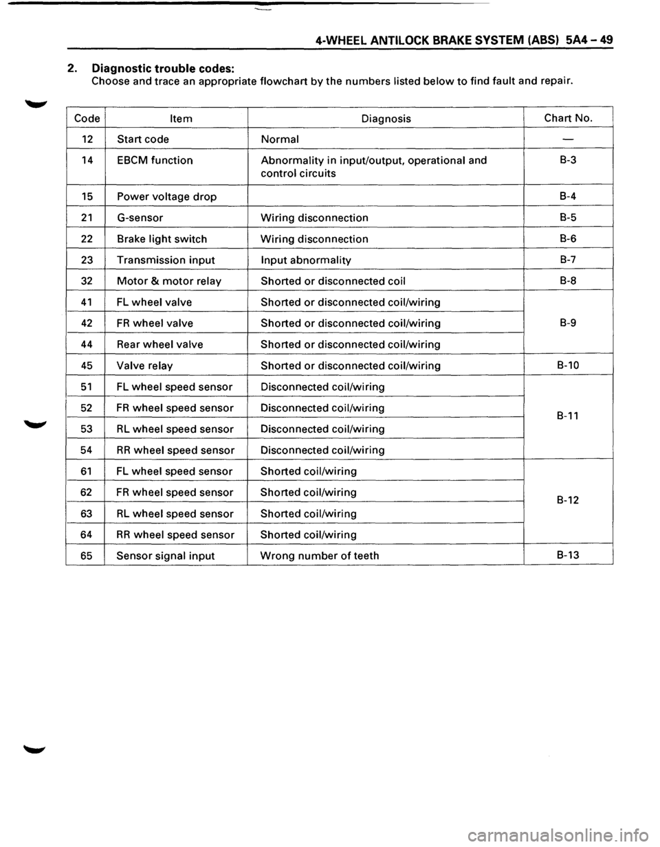
4-WHEEL ANTILOCK BRAKE SYSTEM (ABS) 5A4-49
2. Diagnostic trouble codes:
Choose and trace an appropriate flowchart by the numbers listed below to find fault and repair.
Code
Item Diagnosis Chart
No.
12 Start code Normal -
14 EBCM function Abnormality in input/output, operational and B-3
control circuits
15 Power voltage drop B-4
21 G-sensor Wiring disconnection B-5
22 Brake light switch Wiring disconnection B-6
23 Transmission input Input abnormality B-7
32 Motor & motor relay
Shorted or disconnected coil B-8
41 FL wheel valve
Shorted or disconnected coil/wiring
42 FR wheel valve
Shorted or disconnected coil/wiring B-9
44 Rear wheel valve Shorted or disconnected coil/wiring
45 Valve relay Shorted or disconnected coil/wiring B-10
51 FL wheel speed sensor Disconnected coil/wiring
52 FR wheel speed sensor Disconnected coil/wiring B-11
53 RL wheel speed sensor Disconnected coil/wiring
54
RR wheel speed sensor Disconnected coil/wiring
61 FL wheel speed sensor Shorted coil/wiring
62 FR wheel speed sensor Shorted coil/wiring B-12
63 RL wheel speed sensor Shorted coil/wiring
64 RR wheel speed sensor Shorted coil/wiring
65 Sensor signal input Wrong number of teeth B-13
Page 485 of 1928
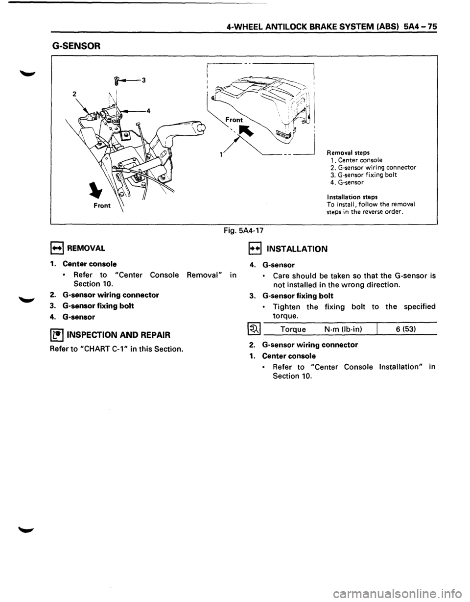
G-SENSOR
, .... ,REMOVAL
1. Center console
4-WHEEL ANTILOCK BRAKE SYSTEM (ABS) 5A4-75
Fig. 5A4-17
Removal steps 1. Center console 2. G-sensor wiring connector 3. G·sensor fixing bolt 4. G-sensor
Installation steps To install, follow the removal steps in the reverse order.
, .. .,, INSTALLATION
4. G-sensor
• Refer to "Center Console Removal" in • Care should be taken so that the G-sensor is
not installed in the wrong direction.
Section 10.
2. G-sensor wiring connector
3. G-sensor fixing bolt
4. G-sensor
IL•ItNSPECTION AND REPAIR
Refer to "CHART
C-1" in this Section.
3. G-sensor fixing bolt
• Tighten the fixing bolt to the specified
torque.
I~I ____ T_o_rq~u~e ____ N~·-m~(lb_·_in~)--~ ___ 6_(_53~) __ __
2. G-sensor wiring connector
1. Center console
• Refer to "Center Console Installation" in
Section
10.