wiring ISUZU TROOPER 1995 Service Manual
[x] Cancel search | Manufacturer: ISUZU, Model Year: 1995, Model line: TROOPER, Model: ISUZU TROOPER 1995Pages: 1928
Page 725 of 1928
DRIVEABILITY AND EMISSIONS 6E2-29
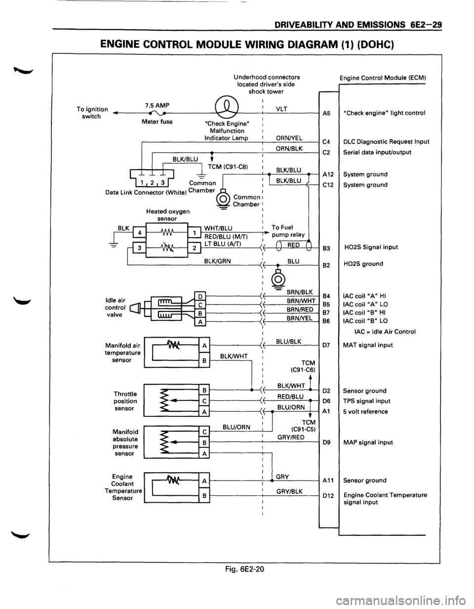
ENGINE CONTROL MODULE WIRING DIAGRAM (1) (DOHC)
Underhood connectors
located driver's side
shock
tower
To ignition
switch 7.5AMP ,.... ~ ®
I
I
Meter fuse I "Check Engine" I Malfunction I Indicator Lamp I
I
'
I 8LK/8LU I
D
I l TCM (C91-C8) 1
~ 1 2 ~ ~ co.;;mo~~ : ata Link Connector (White) Chamber 1 0 Common1 Chamber 1 Heated oxygen -= I
rg
=F
leair s ontrol C] alve
ld c v
M
te anifold
air
mperature sensor
Throttle position sensor
Manifold absolute pressure sensor
Engine
Coolant
T emperature
Sensor
sensor I
I
-A/IN-1:'1 WHT/8LU I
~ RED/8LU (M/TI I
~ ""21 L T 8LU (A/TI II ....::....1 ,1,
8LK/GRN :,
I
I
I
I
cam l:
I
I
Au A )I y"-\1 r--
8 8LK/WHT I I
I
I
I
8 ~ 1--II
~ r£ \ 'I A ,1,
8LU/ORN I
r£ ~ I
8 ~ f--I A I
I
I
_A& a A I y"-I r--I 8 I
I
I
Fig. 6E2-20
VLT
ORNNEL
ORN/8LK
8LK/8LU
I 8LK/8LU
To Fuel
pump relay
( ) RED ( v v
8LU
~ -8RN/8LK
8RN/WHT
8RN/RED
8RNNEL
8LU/8LK
TCM (C91-C6)
8LK/WHT !
RED/8LU
8LU/ORN
TCtM
(C91-C5)
GRY/RED
GRY
GRY/8LK Engine
Control
Module (ECMI
.-----
AS "Check engine" light control
C4 DLC Diagnostic Request lnpu
C2 Serial data input/output
A12 System ground
C12 System ground
83
H02S Signal input
82 H02S ground
84
lAC coil "A" HI
85 lAC coil "A" LO
87 lAC coil "8" HI
86 lAC coil "8" LO
lAC = Idle Air Control
D7 MAT signal input
D2 Sensor ground
D6 TPS signal input
A1 5 volt reference
D9 MAP signal input
A11 Sensor ground
D12 Engine Coolant Temperatur e signal input
......__
Page 726 of 1928
6E2-30 DRIVEABILITY AND EMISSIONS
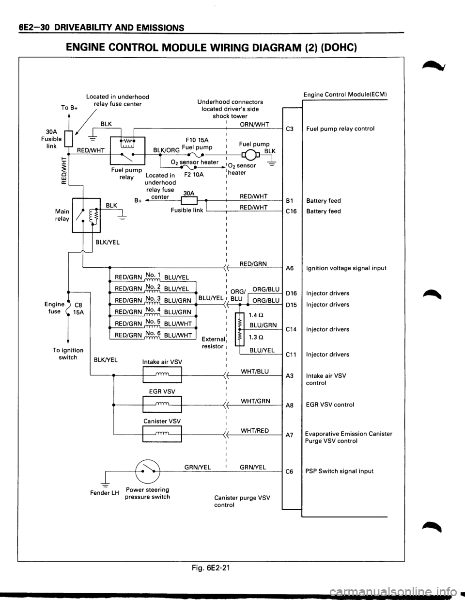
ENGINE CONTROL MODULE WIRING DIAGRAM (2) (DOHC)
Located in underhood Engine Control Module(ECM)
T B relay
fuse center Underhood connectors
o + located
driver's side r--. / shock tower
/ I BLK.---+-I_: ~==-----------+-: __ O_R_N...:./W_H_T_--1 C3 Fuel pump relay control
Fusible
= tti F10 15A 1
30A
I' k I 1 Fuel pump In REO/WHT BLK/ORG Fu:.._pu~
~ ~-T 02 sensor heater :
0 _ ~ I ~ 2 sensor -<. Fuel pump ~ lh @ relay Located in F2 10A 1 eater
a:'---underhood
relay fuse I
BLK 30A
1 B+ _..;c:..::ec:..:n-=.:te:.:..r_-1 REO/WHT B1 Battery
feed
Fusible link
lL---,--1 _ _:.:R:.=E-==O'-'fW:..:..:....:H-=-T---i C16 Battery feed Main relay
BLK/YEL I
I
I
I
I
I
I
L---~--------------<)1 REO/GRN ,1, A6
Engine ') CB fuse 15A
To ignition switch
REO/GRN No. 1
BLU/YEL I
REO/GRN No.2 BLU/YEL : ORG/ ORG/BLU 016
015
REO/GRN No.3 BLU/GRN
BLU/YEL }1 BLU l ORG/BLU L....::-=-=.:...=.:._.._ __ -<
REO/GRN No.4
BLU/GRN \'
REO/GRN No. 5
BLU/WHT
REO/GRN No. 6 BLU/WHT I
I
External1 resistor 1 I
1.4 n
t-+--B_L-'U/_G_R_N--1 C
14
1.3Q
'---=B:..::L:..::U_:_IY;_:E:.:L~ C 11 BLK/YEL Intake air VSV I
I
l
I I t.__-1~-----< t--...:...W:..:.H.:....:.T.:...::/B:..::Lc::.U_-1 A
3
I
I
I
EGRVSV
'---111 ____ -<' (-_...:...W.:....:.H.:....:.T.:...c/G=-R_N_-1 AB
Canister VSV 1
I 1
/ WHT/REO I '---1~-----<,f--,--"------1 A7 ~------~ I I I I
~r---G~RN~/Y~E_L __ 1 __ G~R_N...:.!Y_EL_~ C 6
Fender
LH Power steering
pressure switch Canister purge VSV
control
Fig. 6E2-21
Ignition voltage signal input
Injector drivers
Injector drivers
Injector drivers
Injector drivers
Intake air VSV
control
EGR VSV control
Evaporative Emission Canister
Purge VSV control
PSP Switch signal input
1111
Page 727 of 1928
DRIVEABILITV AND EMISSIONS 6E2-31
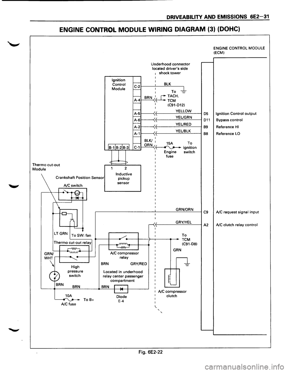
ENGINE CONTROL MODULE WIRING DIAGRAM (3) (DOHC)
Thermo cut-out Module Ignition
Control
Module
J
Underhood connector located driver's side 1 shock tower I
~r---~: ___ B~L=K~--~
I-: To -d::-1--A-4 I-
BRN I, r--TACH. \~TCM I (C91-D12) I
~1-----\(. f-------...:.Y.=.E:::LL:.:O:..:W:..:._--1 OS
~L-----'~
11---\-{' t----Y:..::E~LJ:..:::B.:::LK~--l BB f.---I BLK/ I f.---ORN 15A To C-1 "\~ ignition
Engine switch
fuse
2
Inductive pickup
sensor
Crankshaft
Position Sensor
NC switch
I ~~ l '--------J
\'r-----.
High
BRN
BRN
]_OA ~ ToB+ A/C fuse
BRN
NC compressor relay
GRY/RED
Located in underhood relay center passenger compartment
BRN I I I "' I
Diode E-4
I
I
-<( ,1,
I
I
GRN/ORN
GRY!YEL
To
TCM (C91-D8l
GRN
n
l
NC compressor clutch
' '
Fig. 6E2-22
C9
A2
ENGINE CONTROL MODULE (ECM)
Ignition Control output
Bypass control
Reference HI
Reference LO
NC request signal input
NC clutch relay control
Page 728 of 1928
6E2-32 DRIVEABILITY AND EMISSIONS
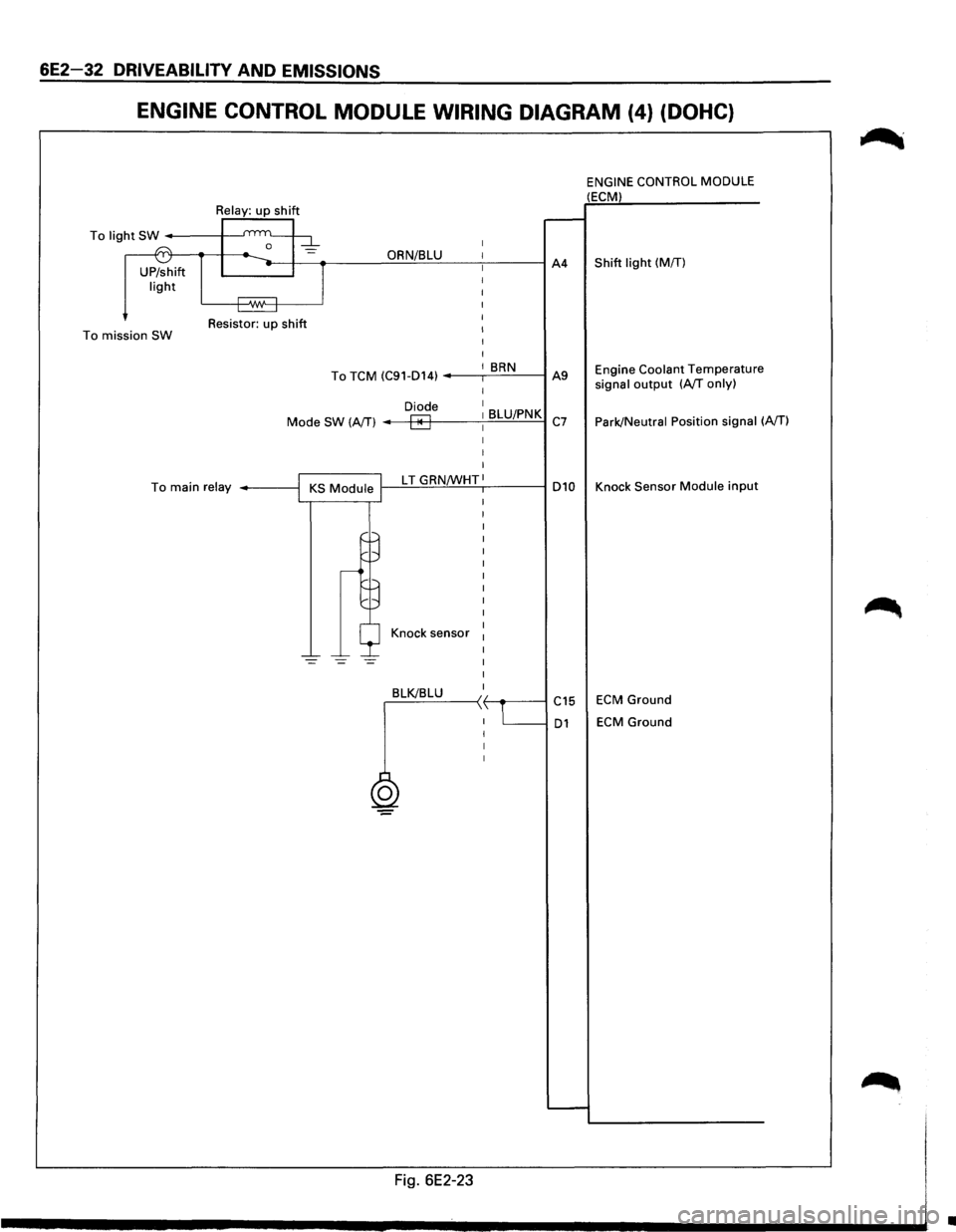
ENGINE CONTROL MODULE WIRING DIAGRAM (4} (DOHC}
ENGINE CONTROL MODULE (ECM)
To light SW ------+---'
= i---(ST-ijl...._ __ -l---=--.---_gO!!R~N/~B~LU~-~---J A4 Shift light (MIT) UP/shift light
To mission SW Resistor: up shift
I
I BRN To TCM (C91-D14) ---.--=:.:.cc....:...._--t A9 Engine Coolant Temperature
signal output (A/T only)
Park/Neutral Position signal
(A/T) Diode I
I BLU/PNK C7 Mode SW (A/T)
I
To main relay ------l 1--=L T-'-=G-'-'-R'-"N/W'-'--'-"H.:....:T,1------i D10 Knock Sensor Module input
Knock sensor
=
,_BL_K!-'-B_L_U_--< ~~----1 C15 ECM Ground
D1 ECM Ground
0
Fig. 6E2-23
•
Page 733 of 1928
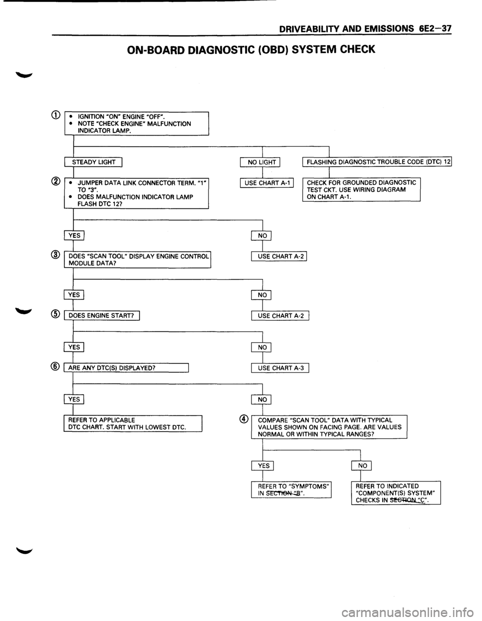
DRIVEABILITY AND EMISSIONS 6E2-37
ON-BOARD DIAGNOSTIC (OBD) SYSTEM CHECK
(j) • IGNITION "ON" ENGINE "OFF".
• NOTE "CHECK ENGINE" MALFUNCTION INDICATOR LAMP.
STEADY LIGHT
@ • JUMPER DATA LINK CONNECTOR TERM. "1" TO "3".
• DOES MALFUNCTION INDICATOR LAMP FLASH DTC 127
@ DOES "SCAN TOOL" DISPLAY ENGINE CONTROL MODULE DATA?
REFER TO APPLICABLE DTC CHART. START WITH LOWEST DTC.
CHECK FOR GROUNDED DIAGNOSTIC TEST CKT. USE WIRING DIAGRAM ON CHART A-1.
@ COMPARE "SCAN TOOL" DATA WITH TYPICAL VALUES SHOWN ON FACING PAGE. ARE VALUES NORMAL OR WITHIN TYPICAL RANGES?
REFER TO INDICATED "COMPONENT(S) SYSTEM" CHECKS IN~·.
Page 736 of 1928
6E2-40 DRIVEABILITY AND EMISSIONS
CHART A-2
NO DATA LINK CONNECTOR (DLC) DATA OR
WILL NOT FLASH DIAGNOSTIC TROUBLE CODE (DTC) 12
"CHECK ENGINE" MALFUNCTION INDICATOR LAMP (MIL) "ON" STEADY
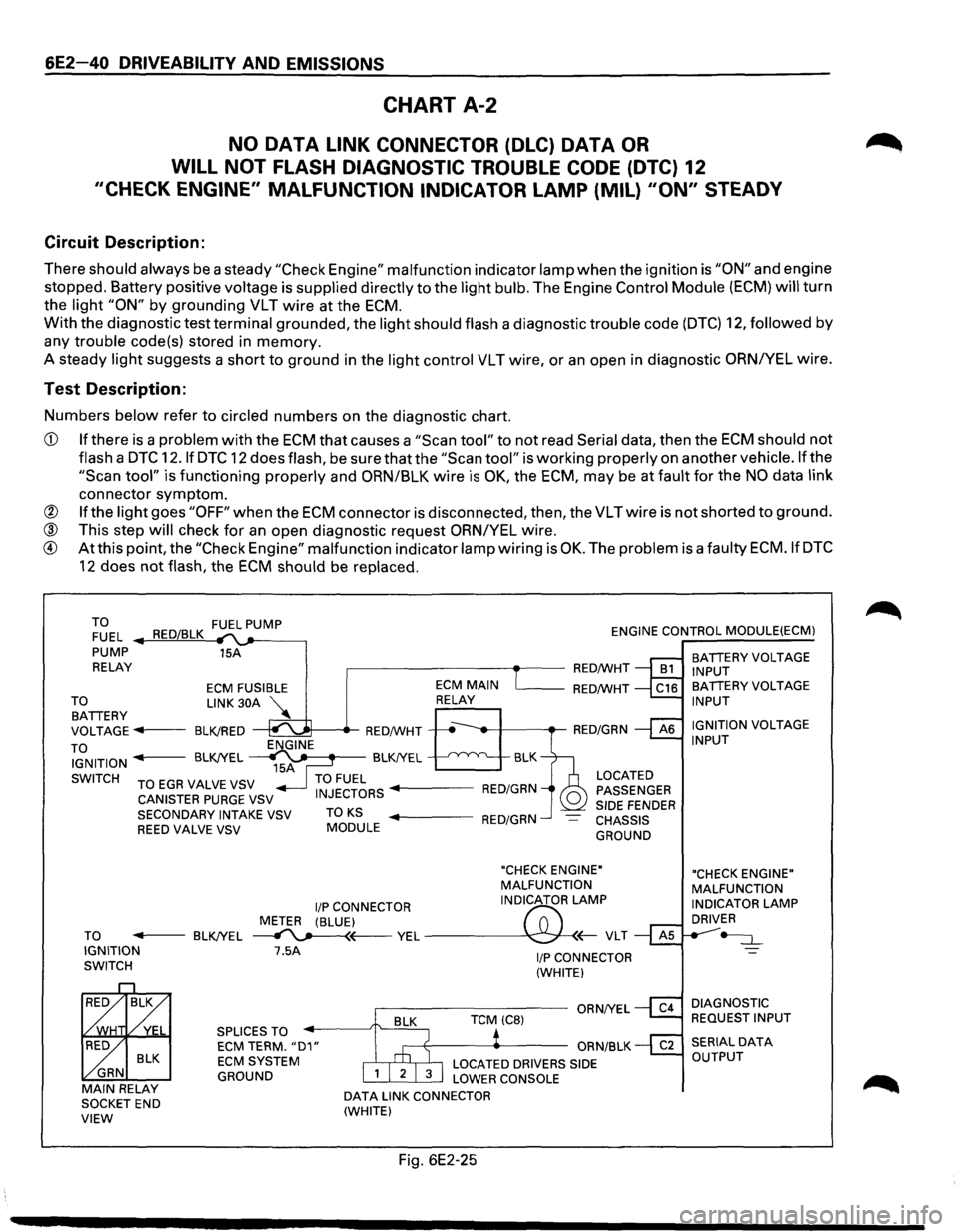
Circuit Description:
There should always be a steady "Check Engine" malfunction indicator lamp when the ignition is "ON" and engine
stopped. Battery positive
voltage is supplied directly to the light bulb. The Engine Control Module (ECM) will turn
the
light "ON" by grounding VLT wire at the ECM.
With the diagnostic test terminal grounded, the light should flash a diagnostic trouble code (DTC) 12, followed by
any trouble code(s) stored in memory.
A steady
light suggests a short to ground in the light control VLT wire, or an open in diagnostic ORNIYEL wire.
Test Description:
Numbers below refer to circled numbers on the diagnostic chart.
CD If there is a problem with the ECM that causes a "Scan tool" to not read Serial data, then the ECM should not
flash a DTC 12.1f DTC 12 does flash, be sure that the "Scan tool" is working properly on anothervehicle.lfthe
"Scan tool" is functioning properly and ORN/BLK wire is OK, the ECM, may be at fault for the NO data link
connector symptom.
@ If the light goes "OFF" when the ECM connector is disconnected, then, the VLTwire is not shorted to ground.
® This step will check for an open diagnostic request ORN/YEL wire.
® At this point, the "Check Engine" malfunction indicator lamp wiring is OK. The problem is a faulty ECM.IfDTC
12 does not flash, the ECM should be replaced.
TO FUEL PUMP
FUEL RED/BLK ENGINE CONTROL MODULE(ECM)
PUMP 15A
RELAY
,.-------------.--RED/WHT
TO BATTERY
ECM FUSIBLE
LINK 30A
VOLTAGE
...,. .. 1---BLK!RED
TO IGNITION
SWITCH ENGINE
15A
'------RED/WHT
BLK
BLK!YEL
~ BLK!YEL
TO EGA VALVE VSV TO FUEL CANISTER PURGE VSV INJECTORS ..._ ___ RED/GRN
LOCATED
PASSENGER
SIDE
FENDER CHASSIS
GROUND
SECONDARY
INTAKE VSV TO KS ..._ ___ RED/GRN REED VALVE VSV MODULE
"CHECK ENGINE"
MALFUNCTION
liP CONNECTOR INDICATOR
LAMP
METER (BLUE)
f'7:'
TO -----BLK!YEL ~~ YEL ---\C:;J-
BLK
GRN
MAIN RELAY SOCKET END VIEW
7.5A
SPLICES TO ECM TERM. "D1" ECM SYSTEM
GROUND
DATA LINK CONNECTOR
(WHITE)
Fig. 6E2-25
I/P CONNECTOR
(WHITE)
BATTERY VOLTAGE
INPUT
BATTERY VOLTAGE
INPUT
IGNITION
VOLTAGE INPUT
"CHECK ENGINE"
MALFUNCTION
INDICATOR
LAMP DRIVER
~
DIAGNOSTIC
REQUEST INPUT
Page 738 of 1928
6E2-42 DRIVEABILITV AND EMISSIONS
CHART A-3
(Page 1 of 3)
ENGINE CRANKS BUT WILL NOT RUN
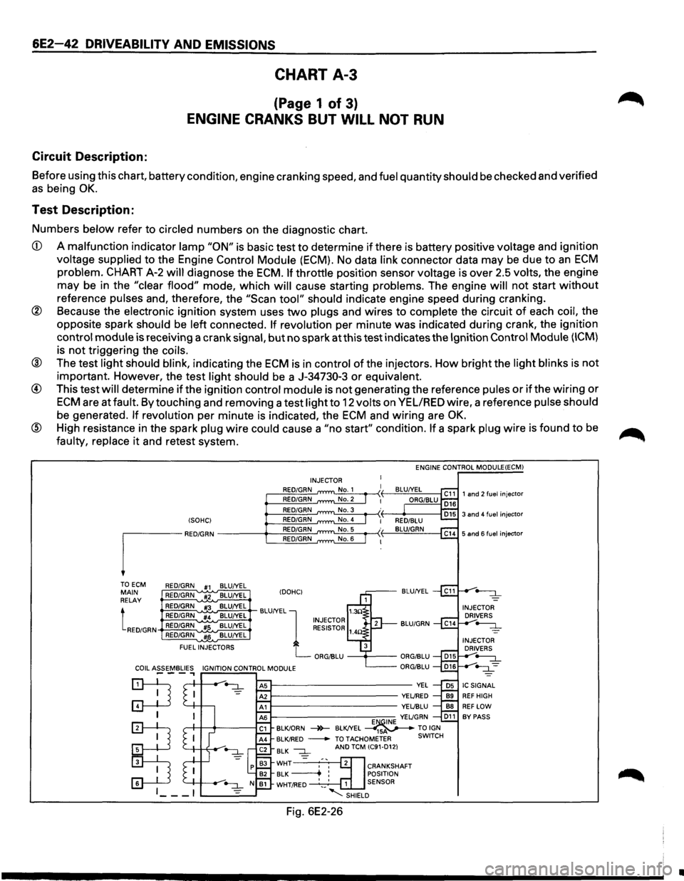
Circuit Description:
Before using this chart, battery condition, engine cranking speed, and fuel quantity should be checked and verified
as being OK.
Test Description:
Numbers below refer to circled numbers on the diagnostic chart.
CD A malfunction indicator lamp "ON" is basic test to determine if there is battery positive voltage and ignition
voltage supplied to the Engine Control Module (ECM). No data link connector data may be due to an ECM
problem. CHART A-2 will diagnose the ECM. If throttle position sensor voltage is over 2.5 volts, the engine
may be in the
"clear flood" mode, which will cause starting problems. The engine will not start without
reference pulses and, therefore, the "Scan tool" should indicate engine speed during cranking.
@ Because the electronic ignition system uses two plugs and wires to complete the circuit of each coil, the
opposite spark
should be left connected. If revolution per minute was indicated during crank, the ignition
control module is receiving a crank signal, but no spark at this test indicates the Ignition Control Module (ICM)
is not triggering the coils.
® The test light should blink, indicating the ECM is in control of the injectors. How bright the light blinks is not
important. However, the test light should be a J-34730-3 or equivalent.
@ This test will determine if the ignition control module is not generating the reference pules or if the wiring or
ECM are at fault. By touching and removing a test light to 12 volts on VEL/RED wire, a reference pulse should
be generated. If revolution per minute is indicated, the ECM and wiring are OK.
® High resistance in the spark plug wire could cause a "no start" condition. If a spark plug wire is found to be
faulty, replace it and retest system.
(SOHC)
I"M"
TOECM RED/GRN #1 BLU/YEL MAIN RED/GRN #2 BLU/YEL
RELAY
tRED/GRN
RED/GRN #3 BLU/YEL
RED/GRN #4 BLU/YEL
RED/GRN
#5 BLU/YEL
RED/GRN
#6 BLU/YEL
FUEL
INJECTORS ENGINE
CONTROL MODULE(ECM)
INJECTOR
RED/GRN
RED/GRN
RED/GRN
RED/GRN
RED/GRN
RED/GRN
IDOHCI BLU/YEL
BLU/YEL
l 1.3!l INJECTOR RESISTOR 1_
ORG/BLU
--+----
E~INE YEL/GRN D11 BLK/ORN -4>-BLK/YEL ----41sv---TO IGN BLK/RED -TOTACHOMETER SWITCH
BLK --:::L =
AND TCM (C91-D12)
CRANKSHAFT
POSITION
1 SENSOR
-........:::SHIELD
Fig. 6E2-26
•
Page 744 of 1928
6E2-48 DRIVEABILITY AND EMISSIONS
CHART A-5
FUEL PUMP RELAY CIRCUIT
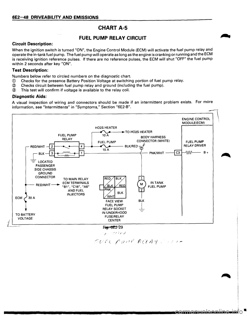
Circuit Description:
When the ignition switch is turned "ON", the Engine Control Module (ECM) will activate the ft:Jel pump relay and
operate the in-tank
fuel pump. The fuel pump will operate as long as the engine is cranking or running and the ECM
is receiving ignition reference pulses. If there are no reference pulses, the ECM will shut "OFF" the fuel pump
within 2 seconds after key
"ON".
Test Description:
Numbers below refer to circled numbers on the diagnostic chart.
CD Checks for the presence Battery Position Voltage at switching portion of fuel pump relay.
® Checks circuit between fuel pump relay and ground (including the fuel pump).
® This test will confirm if voltage is available to the relay coil.
Diagnostic Aids:
A visual inspection of wiring and connectors should be made if an intermittent problem exists. For more
information, see
"lntermittents" in "Symptoms," Section "6E2-B".
ECM
FUEL PUMP
RELAY
H02S HEATER _. ___ .,.TO H02S HEATER
10 A BODY HARNESS CONNECTOR (WHITE)
RED/WHT 1---_.__.., '"..._.. __ BLK!RED...J
_[BLK
-= LOCATED PASSENGER SIDE CHASSIS
GROUND
CONNECTOR
TO MAIN RELAY
RED/WHT---+-ECM TERMINALS "81", "C16", 11A6" AND FUEL INJECTORS
FACE VIEW FUEL PUMP RELAY SOCKET
BLK
j__
IN TANK FUEL PUMP
TO BATIERY IN UNDERHOOD ENGINE
CONTRO:-- MODULE(ECM) ·.
FUEL PUMP RELAY DRIVER
8+
VOLTAGE
FUSE/RELAY
i L---------------------------C-EN_T_E_R _______________________ ~
lL---f~. 6E2=29
/
'"·:c·t( (7.::!11t.~ l<(/1) 1/. i-
•
Page 754 of 1928
6E2-58 DRIVEABILITY AND EMISSIONS
Circuit Description:
DIAGNOSTIC TROUBLE CODE (DTC) 13
HEATED OXYGEN SENSOR (H02S) CIRCUIT
(OPEN/GROUNDED CIRCUIT)
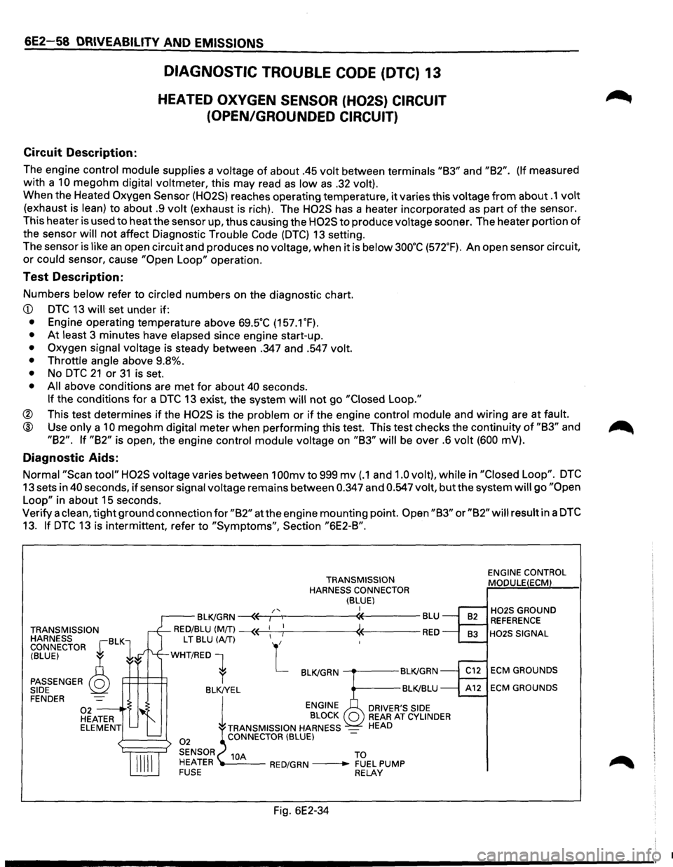
The engine control module supplies a voltage of about .45 volt between terminals "83" and "82". (If measured
with a
10 megohm digital voltmeter, this may read as low as .32 volt).
When the Heated Oxygen Sensor (H02S) reaches operating temperature, it varies this voltage from about .1 volt
(exhaust is lean) to about .9 volt (exhaust is rich). The H02S has a heater incorporated as part of the sensor.
This heater is used to
heatthe sensor up, thus causing the H02S to produce voltage sooner. The heater portion of
the sensor
will not affect Diagnostic Trouble Code (DTC) 13 setting.
The sensor
is like an open circuit and produces no voltage, when it is below 3oo·c (572.F). An open sensor circuit,
or could sensor, cause "Open Loop" operation.
Test Description:
Numbers below refer to circled numbers on the diagnostic chart.
• At least 3 minutes have elapsed since engine start-up.
• Oxygen signal voltage is steady between .347 and .547 volt.
• Throttle angle
above 9.8%.
• No DTC 21 or 31 is set.
• All above conditions are met for about 40 seconds.
If the conditions for a DTC 13 exist, the system will not go "Closed Loop."
® This test determines if the H02S is the problem or if the engine control module and wiring are at fault.
@ Use only a 10 megohm digital meter when performing this test. This test checks the continuity of "83" and
"82". If "82" is open, the engine control module voltage on "83" will be over .6 volt (600 mV).
Diagnostic Aids:
Normal "Scan tool" H02S voltage varies between 1 OOmv to 999 mv (.1 and 1.0 volt), while in "Closed Loop". DTC
13 sets in 40 seconds, if sensor signal voltage remains between 0.347 and 0.547 volt, but the system will go "Open
Loop"
in about 15 seconds.
Verify a
clean, tight ground connection for "82" at the engine mounting point. Open "83" or "82" will result in a DTC
13. If DTC 13 is intermittent, refer to "Symptoms", Section "6E2-8".
TRANSMISSION
HARNESS BLK CONNECTOR r 1
TRANSMISSION
HARNESS CONNECTOR
(BLUE) I /'< r--BLK/GRN ~~,---.,------«----BLU
RED/BLU (MIT) --« ! « RED
(BLUE) ~
PASSENGER Q SIDE
L T BLU (A/T) L
WHT/RED 1
P=H=~ r BLK/GRN ---.---BLK!GRN
BLK!YEL BLK!BLU FENDER
02 -----·'$ HEATER ELEMENT
02
l
ENGINE
BLOCK
TRANSMISSION HARNESS
-CONNECTOR (BLUE)
DRIVER'S SIDE REAR AT CYLINDER HEAD
SENSOR 10A TO
HEATER ---RED/GRN --• FUEL PUMP FUSE RELAY
Fig. 6E2-34
ENGINE CONTROL
MODULE(ECM)
H02S GROUND REFERENCE
H02S SIGNAL
ECM GROUNDS
ECM GROUNDS
•
Page 756 of 1928
6E2-60 DRIVEABILITY AND EMISSIONS
DIAGNOSTIC TROUBLE CODE (DTC) 14A
ENGINE COOLANT TEMPERATURE (ECT) SENSOR CIRCUIT
(HIGH
TEMPERATURE INDICATED)
Circuit Description:
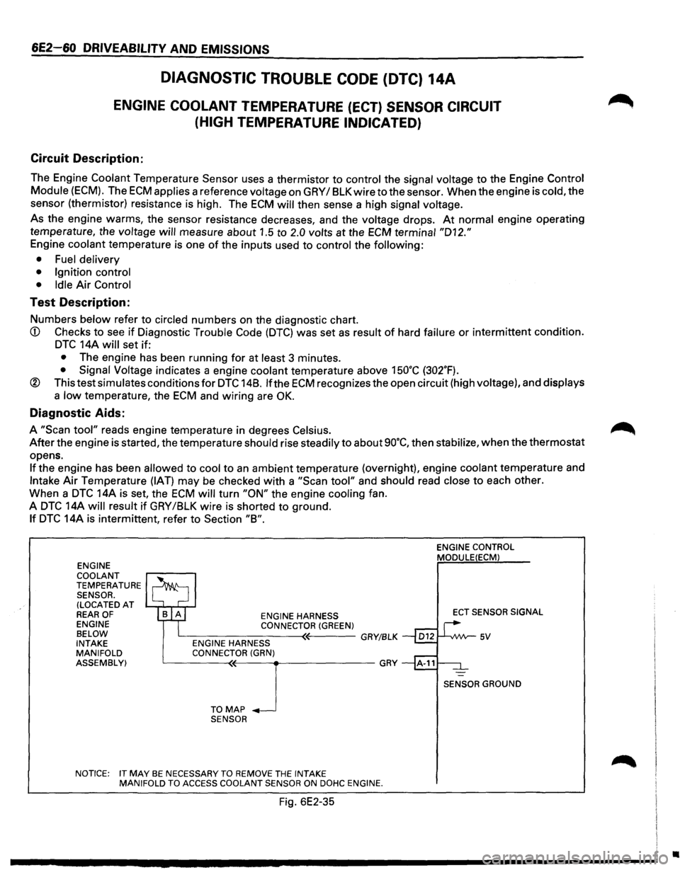
The Engine Coolant Temperature Sensor uses a thermistor to control the signal voltage to the Engine Control
Module
(ECM). The ECM applies a reference voltage on GRY I 8LK wire to the sensor. When the engine is cold, the
sensor (thermistor) resistance is high. The
ECM will then sense a high signal voltage.
As the engine warms, the sensor resistance decreases, and the voltage drops. At normal engine operating
temperature, the
voltage will measure about 1.5 to 2.0 volts at the ECM terminal "D12."
Engine coolant temperature is one of the inputs used to control the following:
• Fuel delivery
• Ignition control
• Idle
Air Control
Test Description:
Numbers below refer to circled numbers on the diagnostic chart.
CD Checks to see if Diagnostic Trouble Code (DTC) was set as result of hard failure or intermittent condition.
DTC 14A will set if:
• The engine has been running for at least 3 minutes.
• Signal Voltage indicates a engine coolant temperature above 15o•c (302.F).
® This test simulates conditions for DTC 148. lfthe ECM recognizes the open circuit (high voltage), and displays
a low temperature, the ECM and wiring are OK.
Diagnostic Aids:
A "Scan tool" reads engine temperature in degrees Celsius.
After the engine is started, the temperature should rise steadily to about so·c, then stabilize, when the thermostat
opens.
If the engine has been allowed to cool to an ambient temperature (overnight), engine coolant temperature and
Intake Air Temperature (IAT) may be checked with a "Scan tool" and should read close to each other.
When a
DTC 14A is set, the ECM will turn "ON" the engine cooling fan.
A
DTC 14A will result if GRY /8LK wire is shorted to ground.
If DTC 14A is intermittent, refer to Section "8".
ENGINE
COOLANT
TEMPERATURE SENSOR. (LOCATED AT REAR OF ENGINE
BELOW
INTAKE
MANIFOLD
ASSEMBLY) ENGINE
HARNESS CONNECTOR(GREEN) L----------<~---GRY/BLK ENGINE HARNESS
CONNECTOR (GRN)
L__ ___ T_O~M(~A-P-~-~-------GRY
SENSOR
NOTICE: IT
MAY BE NECESSARY TO REMOVE THE INTAKE
MANIFOLD TO ACCESS COOLANT SENSOR ON DOHC ENGINE.
Fig. 6E2-35
ENGINE CONTROL MODULE(ECM)
ECT SENSOR SIGNAL
SENSOR GROUND
•