wiring ISUZU TROOPER 1995 Owner's Manual
[x] Cancel search | Manufacturer: ISUZU, Model Year: 1995, Model line: TROOPER, Model: ISUZU TROOPER 1995Pages: 1928
Page 648 of 1928
6C-6 ENGINE FUEL
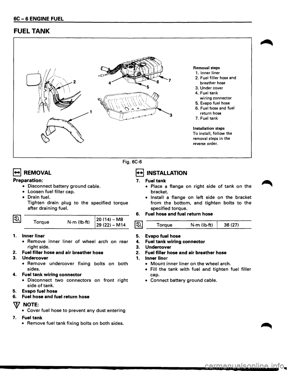
FUEL TANK
7
1 3
Removal steps
1.1nnerliner
2. Fuel filler hose and
breather hose
3. Under cover
4.
Fuel tank
wiring connector
5. Evapo fuel hose
6.
Fuel hose and fuel
return hose
7. Fuel tank
Installation steps
To
install, follow the
removal steps in the
reverse order.
Fig. 6C-6
B REMOVAL
Preparation:
• Disconnect battery ground cable.
•
Loosen fuel filler cap.
• Drain fuel.
Tighten drain plug to the specified torque
after draining fuel.
Torque
1. Inner liner
N·m (lb·ft) 20 (14)-M8
29 (22)-M14
• Remove
inner liner of wheel arch on rear
right side.
2.
Fuel filler hose and air breather hose
3.
Undercover
• Remove undercover fixing bolts on both
sides.
4. Fuel tank wiring connector
• Disconnect two connectors on front right
side of tank.
5. Evapo fuel hose
6. Fuel hose and fuel return hose
W NOTE:
• Cover fuel hose to prevent any dust entering
7. Fuel tank
• Remove fuel tank fixing bolts on both sides.
I!!] INSTALLATION
7.
6.
Fuel tank
• Place a flange on right side of tank on the
bracket.
• Install a flange on left side on the bracket
from the bottom, and tighten bolts to the
specified torque.
Fuel hose and fuel return hose
Torque N·m Ob·ft) 36 (27)
5. Evapo fuel hose
4. Fuel tank wiring connector
3. Undercover
2. Fuel filler hose and air breather hose
1. Inner liner
• Mount inner liner on the wheel arch.
• Fill the tank with fuel and tighten fuel filler
cap.
• Connect battery ground cable.
Page 649 of 1928
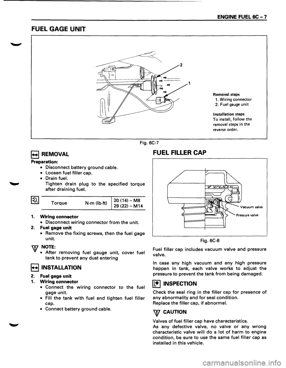
FUEL GAGE UNIT
1
ENGINE FUEL 6C - 7
Removal steps
1. Wiring connector
2. Fuel gauge unit
Installation steps
To
install, follow the
removal steps in the
reverse order.
Fig. 6C-7
E3REMOVAL ~F_U_E_L_F_IL_L_ER __ C_A_P ____________ ~
Preparation:
• Disconnect battery ground cable.
•
Loosen fuel filler cap.
• Drain fuel.
Tighten drain plug to the specified torque
after draining fuel.
Torque
1. Wiring connector
N-m (lb·ft) 20 (14)-M8
29 (22)-M14
• Disconnect wiring connector from the unit.
2. Fuel
gage unit
• Remove the fixing screws, then the fuel gage
unit.
w NOTE:
• After removing fuel gauge unit, cover fuel
tank to prevent any dust entering
B INSTALLATION
2. Fuel gage unit
1. Wiring connector
• Connect the wiring connector to the fuel
gage unit.
• Fill the tank with fuel and tighten fuel filler
cap.
• Connect battery ground cable.
Vacuum valve
Pressure valve
Fig. 6C-8
Fuel filler cap includes vacuum valve and pressure
valve.
In
case any high vacuum and any high pressure
happen in tank, each
valve works to adjust the
pressure to prevent the tank from being damaged.
(1!] INSPECTION
Check the seal ring in the filler cap for presence of
any abnormality and for seal condition.
Replace the filler cap, if abnormal.
\f CAUTION
Valves of fuel filler cap have characteristics.
As any defective valve, no valve or any wrong
characteristic valve will do a lot of harm to engine
condition, be sure to use the same fuel filler cap as
installed in this vehicle.
Page 662 of 1928
602 - 4 CRANKING SYSTEM
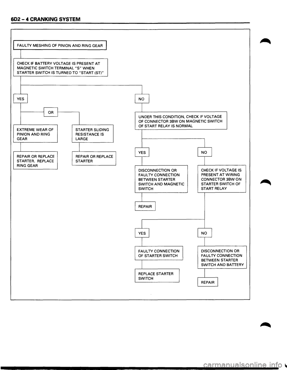
FAULTY MESHING OF PINION AND RING GEAR I
CHECK IF BATTERY VOLTAGE IS PRESENT AT MAGNETIC SWITCH TERMINAL "S" WHEN STARTER SWITCH IS TURNED TO "START (ST)"
YES
I NO I
I OR I I
I
UNDER THIS CONDITION, CHECK IF VOLTAGE OF CONNECTOR 3BW ON MAGNETIC SWITCH
OF START RELAY IS NORMAL EXTREME WEAR OF STARTER SLIDING
PINION AND RING RESISTANCE IS GEAR LARGE
I
I YES I NO I REPAIR OR REPLACE REPAIR OR REPLACE STARTER. REPLACE STARTER
RING GEAR
DISCONNECTION OR CHECK IF VOLTAGE IS
FAULTY CONNECTION PRESENT AT WIRING
BETWEEN STARTER
CONNECTOR 3BW ON
SWITCH
AND MAGNETIC STARTER
SWITCH OF
SWITCH START RELAY
REPAIR I
YES I NO I
FAULTY CONNECTION
DISCONNECTION OR
OF STARTER
SWITCH FAULTY CONNECTION BETWEEN STARTER
SWITCH AND BATTERY
REPLACE
STARTER
I SWITCH REPAIR l
Page 665 of 1928
CRANKING SYSTEM 602 -7
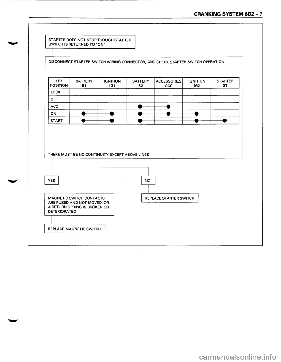
STARTER DOES NOT STOP THOUGH STARTER
SWITCH IS RETURNED TO "ON"
DISCONNECT STARTER SWITCH WIRING CONNECTOR, AND CHECK STARTER SWITCH OPERATION.
KEY
BATTERY IGNITION BATTERY ACCESSORIES IGNITION STARTER
POSITION B1 IG1 B2 ACC IG2 ST
LOCK
OFF
ACC
--- -ON ----------START ----------
THERE MUST BE NO CONTINUITY EXCEPT ABOVE LINES
I
YES I I NO
I
MAGNETIC SWITCH CONTACTS I REPLACE STARTER SWITCH J ARE FUSED AND NOT MOVED, OR A RETURN SPRING IS BROKEN OR DETERIORATED
REPLACE
MAGNETIC SWITCH I
Page 666 of 1928
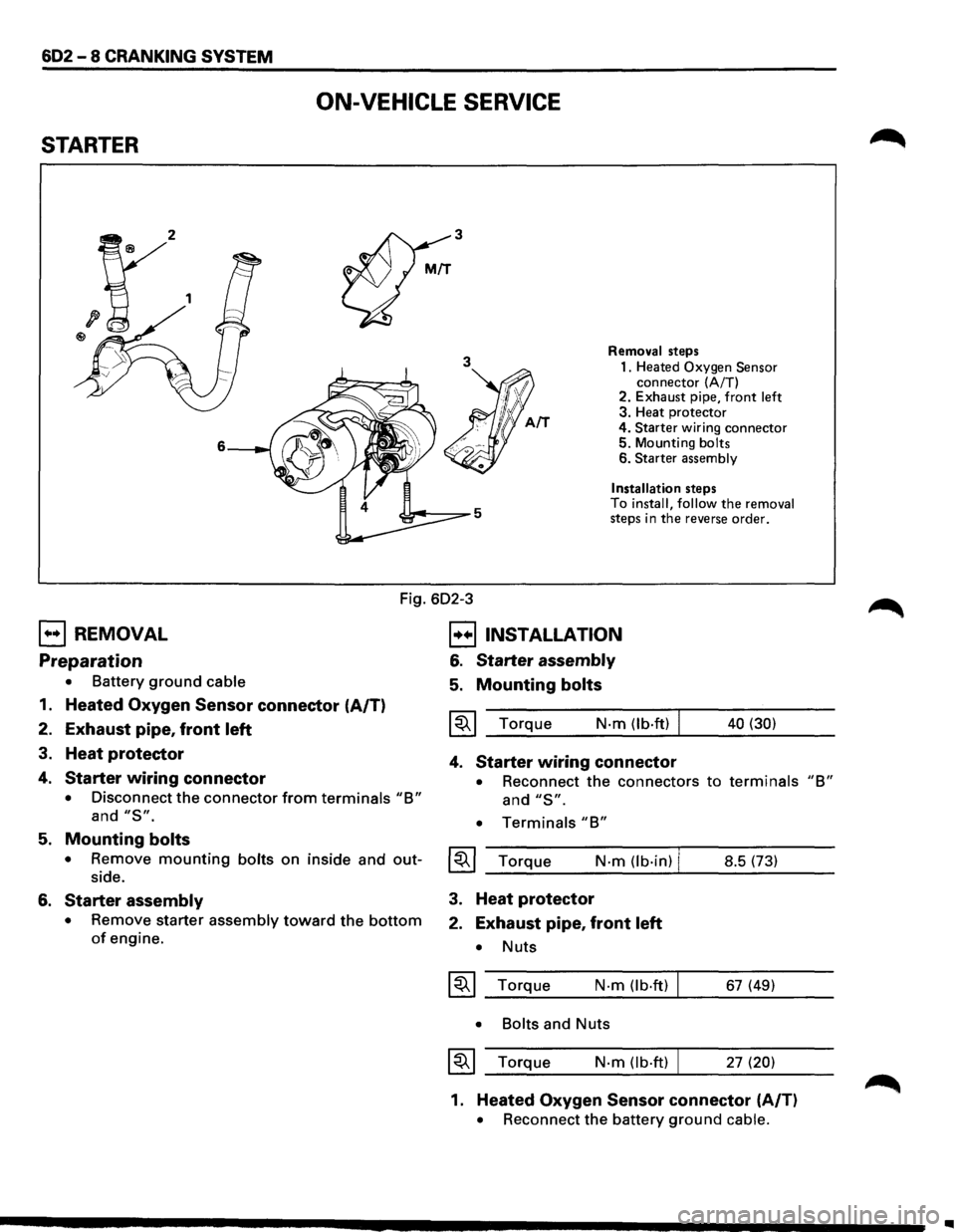
602-8 CRANKING SYSTEM
ON-VEHICLE SERVICE
STARTER
3
3
6
Removal steps
1. Heated
Oxygen Sensor connector (A/T)
2. Exhaust pipe, front left 3. Heat protector
4.
Starter wiring connector 5. Mounting bolts 6. Starter assembly
Installation
steps
To install, follow the removal steps in the reverse order.
Fig. 602-3
EJ REMOVAL
Preparation
• Battery ground cable
1. Heated Oxygen Sensor connector (A/T)
2. Exhaust pipe, front left
3. Heat protector
4. Starter wiring connector
• Disconnect the connector from terminals "B"
and "S".
B INSTALLATION
6. Starter assembly
5. Mounting bolts
~~~ Torque N·m (lb·ft) I
4. Starter wiring connector
40 (30)
• Reconnect the connectors to terminals "B"
and "S".
• Terminals "B"
5. Mounting bolts
• Remove mounting bolts on inside and out-~~~ Torque N·m (lb·in) I side. __ _;_ ______ -J.... ______ _ 8.5 (73)
6. Starter assembly
• Remove starter assembly toward the bottom
of engine.
3. Heat protector
2. Exhaust pipe, front left
• Nuts
~~~ Torque N·m (lb.ft)
• Bolts
and Nuts
~~~ Torque N·m (lb·ft) I
67 (49)
27
(20)
1. Heated Oxygen Sensor connector (A/T)
• Reconnect the battery ground cable.
..
Page 679 of 1928
CHARGING SYSTEM 603 -3
DIAGNOSIS
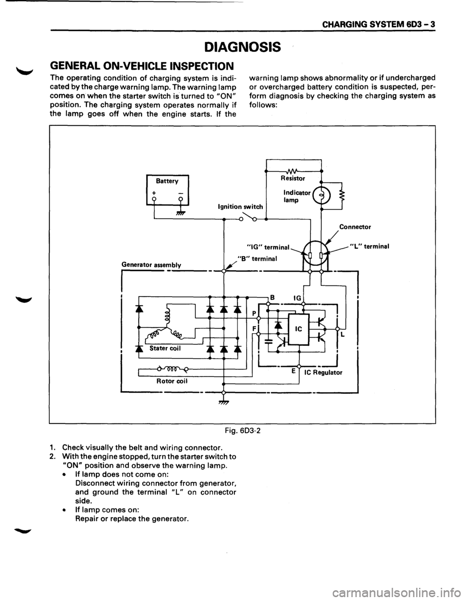
GENERAL ON-VEHICLE INSPECTION
The operating condition of charging system is indi
cated
by the charge warning lamp. The warning lamp
comes on when the starter switch is turned to "ON"
position. The charging system operates normally if
the lamp goes off when the engine starts. If the
Battery
+
warning lamp shows abnormality or if undercharged
or overcharged battery condition is suspected, per
form diagnosis by checking the charging system as
follows:
Resistor
Ignition switch
"B" terminal
Fig. 603-2
1. Check visually the belt and wiring connector.
2. With the engine stopped, turn the starter switch to
"ON" position and observe the warning lamp.
• If lamp does not come on:
Disconnect
wiring connector from generator,
and
ground the terminal "L" on connector
side.
• If lamp comes on:
Repair
or replace the generator.
Connector
"L" terminal
l
Page 680 of 1928
603 - 4 CHARGING SYSTEM
ON-VEHICLE SERVICE
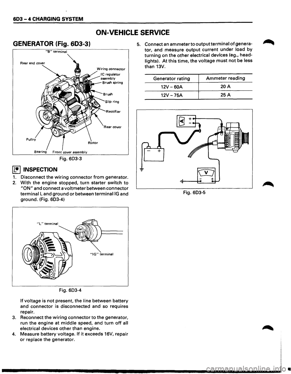
GENERATOR (fig. 603-3}
"B" terminal
Pullry
Fig. 603-3
~ INSPECTION
Wiring connector
I C regulator
assembly
Brush spring
ifier
Rear cover
1. Disconnect the wiring connector from generator.
2. With the engine stopped, turn starter switch to
"ON" and connect a voltmeter between connector
terminal Land ground or between terminaiiG and
ground. (Fig. 603-4)
"IG" terminal
Fig. 603-4
If voltage is not present, the line between battery
and
connector is disconnected and so requires
repair.
3. Reconnect the wiring connector to the generator,
run the
engine at middle speed, and turn off all
electrical
devices other than engine.
4. Measure battery voltage. If it exceeds 16V, repair
or replace the generator.
5. Connect an ammeter to outputterminal of genera
tor, and measure output current under load by
turning on the other electrical devices (eg., head
lights). At this time, the voltage must not be less
than 13V.
Generator rating
Ammeter reading
12V-60A 20A
12V -75A 25A
Fig. 603-5
•
Page 681 of 1928
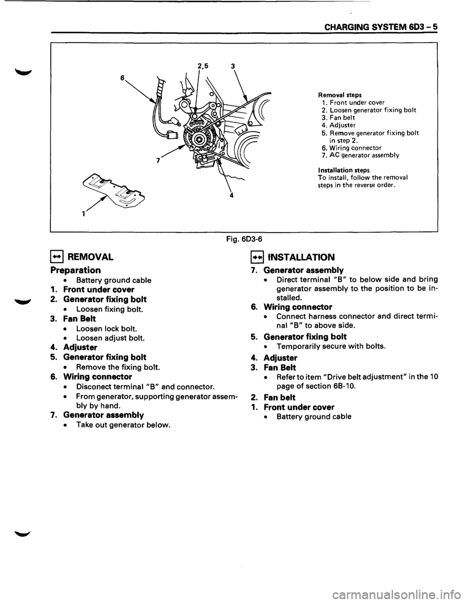
2,5 3
6 4
CHARGING SYSTEM 603 - 5
Removal steps
1. Front under cover
2. Loosen generator fixing bolt
3. Fan belt
4. Adjuster
5. Remove generator fixing bolt
in step 2. 6. Wiring connector
7. AC generator assembly
Installation steps To install, follow the removal
steps in
the reverse order.
Fig. 603-6
E] REMOVAL
Preparation
• Battery ground cable
1. Front under cover
2. Generator fixing bolt
• Loosen fixing bolt.
3. Fan Belt
• Loosen lock bolt.
•
Loosen adjust bolt.
4. Adjuster
5. Generator fixing bolt
• Remove the fixing bolt.
6. Wiring connector
• Disconect terminal "B" and connector.
• From generator, supporting generator assem
bly by hand.
7. Generator assembly
• Take out generator below.
EJ INSTALLATION
7. Generator assembly
• Direct terminal "B" to below side and bring
generator assembly to the position to be in
stalled.
6. Wiring connector
• Connect harness connector and direct termi
nal "B" to above side.
5. Generator fixing bolt
• Temporarily secure with bolts.
4. Adjuster
3. Fan Belt
• Refer to item "Drive belt adjustment" in the 10
page of section 6B-1 0.
2. Fan belt
1. Front under cover
• Battery ground cable
Page 693 of 1928
[!!) INSTALLATION
2. Spark plugs
• Tighten spark plugs to the specified torque.
1. Spark plug wires
• Connect high tension cables to correct termi
nals respectively.
~~~ Torque N·m (lb·ft) I
ELECTRONIC IGNITION (EI)
ASSEMBLY
EJ REMOVAL
Preparation
• Disconnect battery ground cable
1. Spark plug wires
2. Wiring connectors
18 (13)
• Disconnect connectors on Engine Control
Module (ECM), power supply and crank angle
sensor.
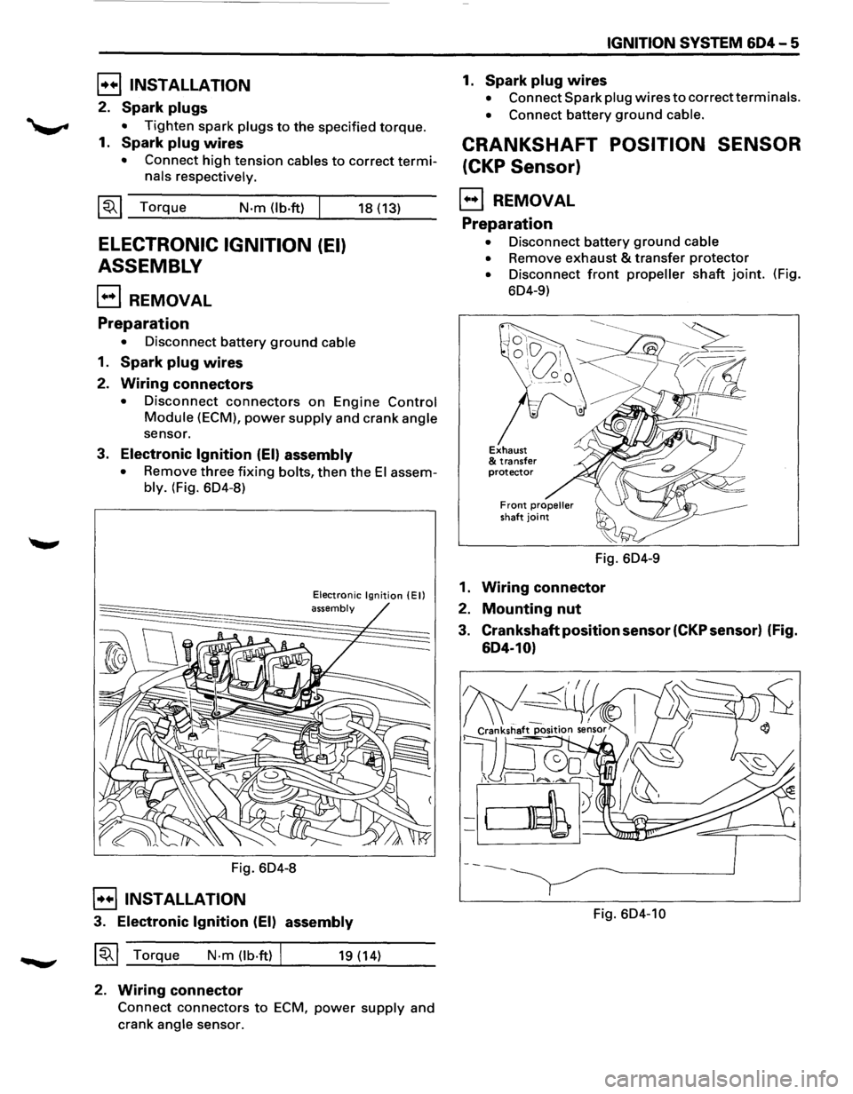
3. Electronic Ignition (EI) assembly
• Remove three fixing bolts, then the El assem
bly. (Fig. 6D4-8)
Fig. 6D4-8
E]INSTALLATION
Electronic Ignition (Ell assembly
3. Electronic Ignition (EI) assembly
~~~ Torque N·m (lb·ftl I 19 (14)
2. Wiring connector
Connect connectors to ECM, power supply and
crank
angle sensor.
IGNITION SYSTEM 604-5
1. Spark plug wires
• Connect Spark plug wires to correct terminals.
• Connect battery ground cable.
CRANKSHAFT POSITION SENSOR
(CKP Sensor)
E) REMOVAL
Preparation
• Disconnect battery ground cable
•
Remove exhaust & transfer protector
• Disconnect front propeller shaft joint. (Fig.
6D4-9)
Fig. 6D4-9
1. Wiring connector
2. Mounting nut
3. Crankshaft position sensor (CKP sensor) (Fig.
604-10)
Fig. 6D4-10
Page 694 of 1928
604-6 IGNITION SYSTEM
B INSTALLATION
3. Crankshaft Position Sensor (CKP sensor)
• Install crankshaft position sensor into the cyl
inder block.
1~1 Before installation, apply small amount of en
gine oil to the 0-ring.
~~~ Torque N-m (lb-in) I 10 (87)
2. Mounting bolt
• Tighten the bolt to the specified torque.
~~~ Torque N-m (lb·ft) I 63 (46)
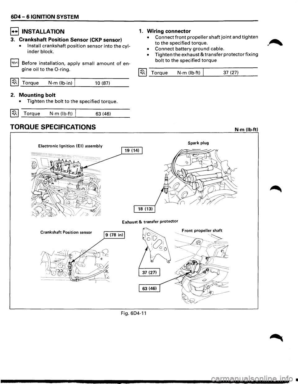
TORQUE SPECIFICATIONS
Electronic Ignition (EI) assembly
1. Wiring connector
• Connect front propeller shaft joint and tighten
to the specified torque.
• Connect battery ground cable.
•
Tighten the exhaust & transfer protector fixing
bolt to the specified torque
~~~ Torque N-m (lb·ft) 37 (27)
N·m (lb·ftl
Spark plug
Exhaust & transfer protector
Crankshaft Position sensor
Fig. 604-11
•