ISUZU TROOPER 1995 Workshop Manual
Manufacturer: ISUZU, Model Year: 1995, Model line: TROOPER, Model: ISUZU TROOPER 1995Pages: 1928
Page 231 of 1928
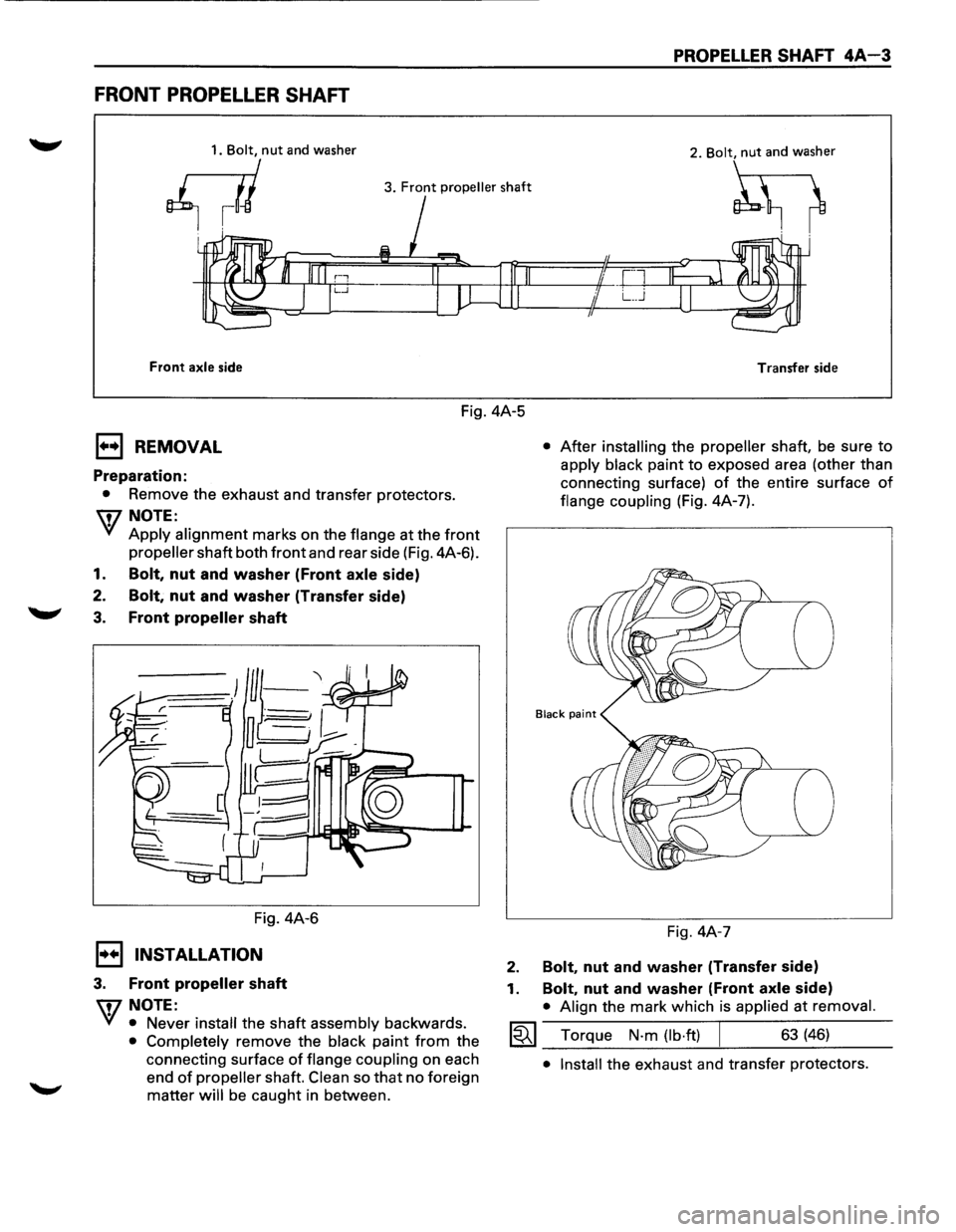
FRONT PROPELLER SHAFT
1. Bolt, nut and washer
Q
3. Front propeller shaft
Front axle side
Fig. 4A-5
1••1 REMOVAL
Preparation:
• Remove the exhaust and transfer protectors.
'\f7 NOTE:
Yf Apply alignment marks on the flange at the front
propeller shaft both front and rear side (Fig. 4A-6).
1. Bolt, nut and washer (Front axle side)
2.
Bolt, nut and washer (Transfer side)
3.
Front propeller shaft
Fig. 4A-6
1••1 INSTALLATION
3. Front propeller shaft
'\f7 NOTE:
2.
1.
PROPELLER SHAFT 4A-3
Transfer side
• After installing the propeller shaft, be sure to
apply black paint to exposed area (other than
connecting surface)
of the entire surface of
flange coupling (Fig. 4A-7).
Fig. 4A-7
Bolt, nut and washer (Transfer side)
Bolt, nut and washer (Front axle side)
• Align the mark which is applied at removal.
Yf • Never install the shaft assembly backwards.
• Completely remove the black paint from the
connecting surface
of flange coupling on each
end
of propeller shaft. Clean so that no foreign
matter
will be caught in between.
I~I_T_:o_rq.::.u....:e_N_·_m_(:__lb_·ft__:)___! ___ 6_3....:...(4_6_) __ _
• Install the exhaust and transfer protectors.
Page 232 of 1928
4A-4 PROPELLER SHAFT
UNIT REPAIR
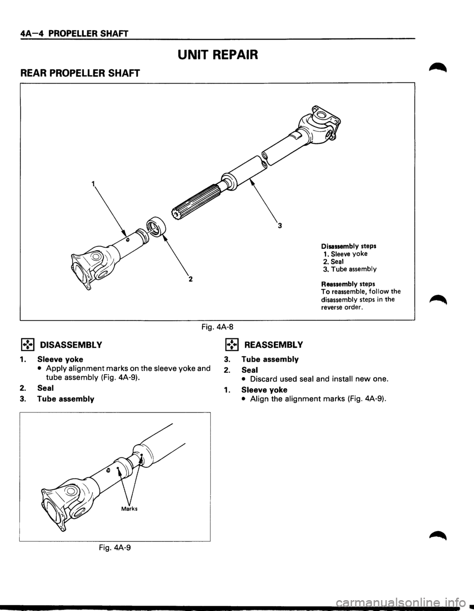
REAR PROPELLER SHAFT
1
2
Disassembly steps
1.
Sleeve yoke
2.
Seal 3. Tube assembly
Reassembly steps
To reassemble, follow the
disassembly steps
in the reverse order.
Fig. 4A-8
l•!•l DISASSEMBLY
1. Sleeve yoke
• Apply alignment marks on the sleeve yoke and
tube
assembly (Fig. 4A-9).
2. Seal
3. Tube assembly
Fig. 4A-9
l•!•l REASSEMBLY
3. Tube assembly
2. Seal
• Discard used seal and install new one.
1. Sleeve yoke
• Align the alignment marks (Fig. 4A-9).
•
Page 233 of 1928
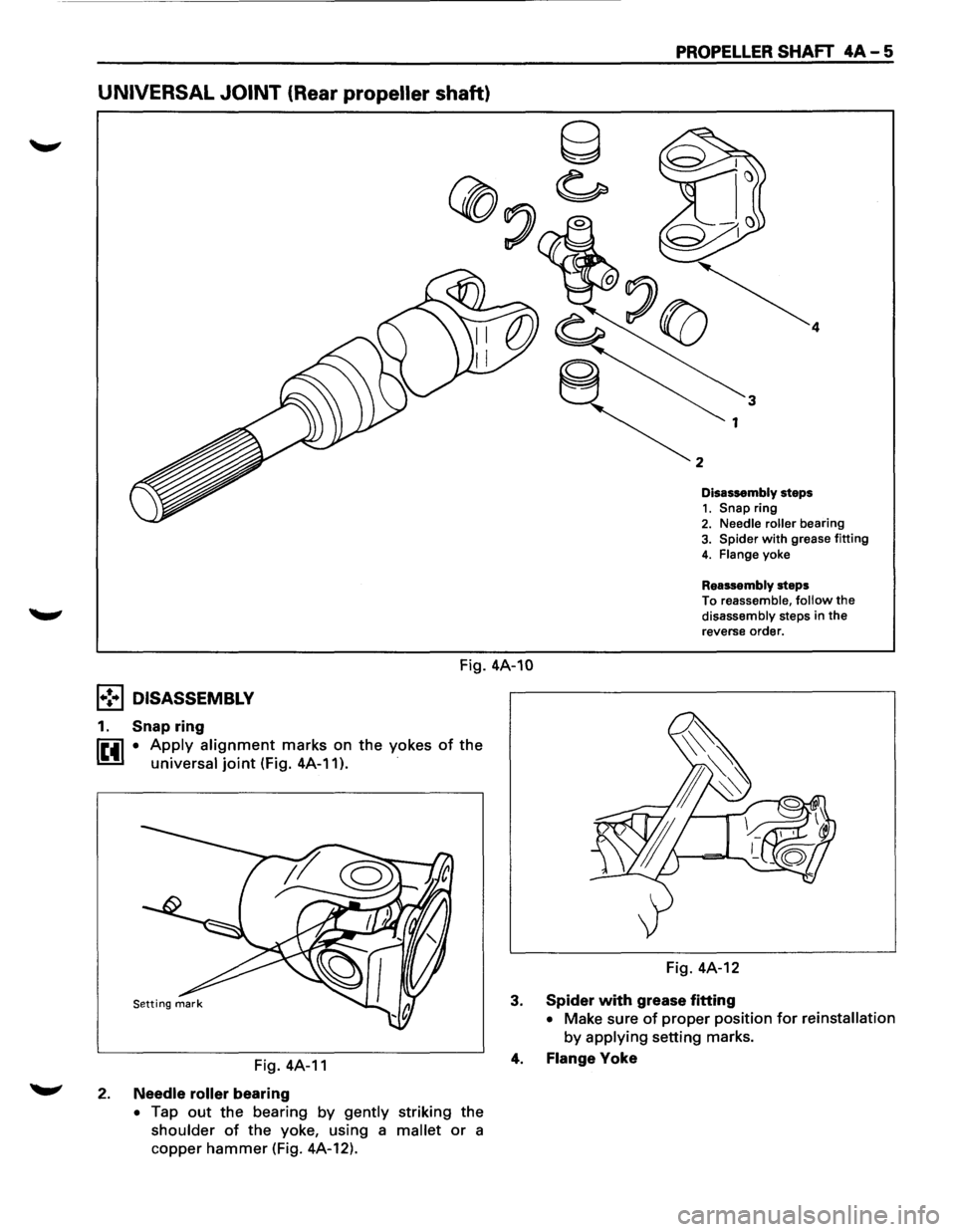
UNIVERSAL JOINT (Rear propeller shaft)
PROPELLER SHAFT 4A-5
2
Disassembly steps 1. Snap ring 2. Needle roller bearing 3. Spider with grease fitting
4. Flange yoke
Reassembly steps
To reassemble, follow the
disassembly steps in the
reverse order.
Fig. 4A-10
l•!•l DISASSEMBLY
1. Snap ring
lttl • Apply alignment marks on the yokes of the
universal joint (Fig. 4A-11 ). ·
Fig. 4A-11
2. Needle roller bearing
• Tap out the bearing by gently striking the
shoulder of the yoke, using a mallet or a
copper
hammer (Fig. 4A-12). Fig.
4A-12
3.
Spider with grease fitting
• Make sure of proper position for reinstallation
by applying setting marks.
4. Flange Yoke
Page 234 of 1928
4A-6 PROPELLER SHAFT
IL•IINSPECTION
AND REPAIR
Make necessary correction or parts replacement if
wear, damage,corrosion or any other abnormal
condition is found through inspection.
NOTE:
When any part of the journal assembly (spider,
needle roller bearing, grease fitting) requires
replacement, be sure to replace the entire assembly.
Visual check
Check the following parts for wear, damage, noise or
any other abnormal conditions.
• Spider
• Needle roller bearing
• Yoke
• Flange
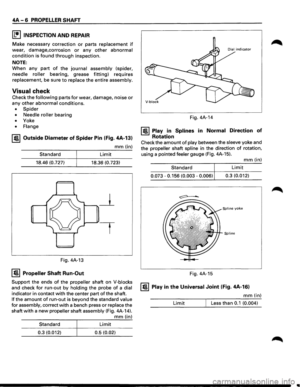
I til Outside Diameter of Spider Pin (fig. 4A-13)
mm (in)
Standard
18.46 (0.727)
Fig. 4A-13
I tJ I Propeller Shaft Run-Out
Limit
18.36 (0.723)
Support the ends
of the propeller shaft on V-blocks
and check for run-out by holding the probe of a dial
indicator in contact with the center part of the shaft.
If the amount of run-out is beyond the standard value
for assembly, correct with a bench press or replace the
shaft
with a new propeller shaft assembly (Fig. 4A-14).
mm (in)
Standard
Limit
0.3 (0.012) 0.5 (0.02) Fig.
4A-14
ltil Play in Splines in Normal Direction of
Rotation
Check the amount of play between the sleeve yoke and
the
propeller shaft spline in the direction of rotation,
using a pointed
feeler gauge (Fig. 4A-15).
mm(in)
Standard Limit
0.073 -0.156 (0.003 -0.006) 0.3
(0.012)
Spline yoke
Spline
Fig. 4A-15
I til Play in the Universal Joint (fig. 4A-16)
mm (in)
Limit Less than 0.1 (0.004)
..
Page 235 of 1928
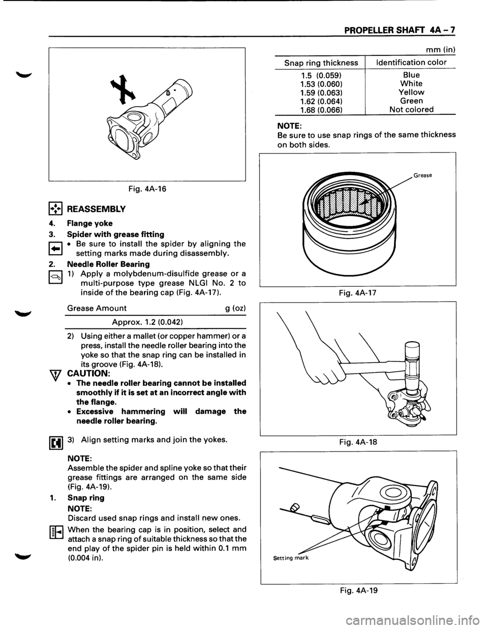
Fig. 4A-16
l•!•l REASSEMBLY
4. Flange yoke
3. Spider with grease fitting
r:::1 • Be sure to install the spider by aligning the
t.=.l setting marks made during disassembly.
2. Needle Roller Bearing
c=::l 1) Apply a molybdenum-disulfide grease or a
D multi-purpose type grease NLGI No. 2 to
inside of the bearing cap (Fig. 4A-17).
Grease
Amount g (oz)
Approx. 1.2 (0.042)
2) Using either a mallet (or copper hammer) or a
press,
install the needle roller bearing into the
yoke so
that the snap ring can be installed in
its groove (Fig. 4A-18).
CAUTION:
• The needle roller bearing cannot be installed
smoothly
if it is set at an incorrect angle with
the
flange.
•
Excessive hammering will damage the
needle roller bearing.
IE41 3) Align setting marks and join the yokes.
NOTE:
Assemble the spider and spline yoke so that their
grease fittings are arranged on the same side
(Fig. 4A-19).
1. Snap ring
NOTE:
Discard used snap rings and install new ones.
I§EI When the bearing cap is in position, select and
- attach a snap ring
of suitable thickness so that the
end play
of the spider pin is held within 0.1 mm
(0.004 in).
PROPELLER SHAFT 4A-7
mm (in)
Snap ring thickness Identification
color
1.5 (0.059)
1.53 (0.060)
1.59 (0.063)
1.62 (0.064)
1.68 (0.066)
NOTE:
Blue
White
Yellow
Green
Not colored
Be sure
to use snap rings of the same thickness
on both sides.
Grease
Fig. 4A-17
Fig. 4A-18
Fig. 4A-19
Page 236 of 1928
4A-8 PROPELLER SHAFT
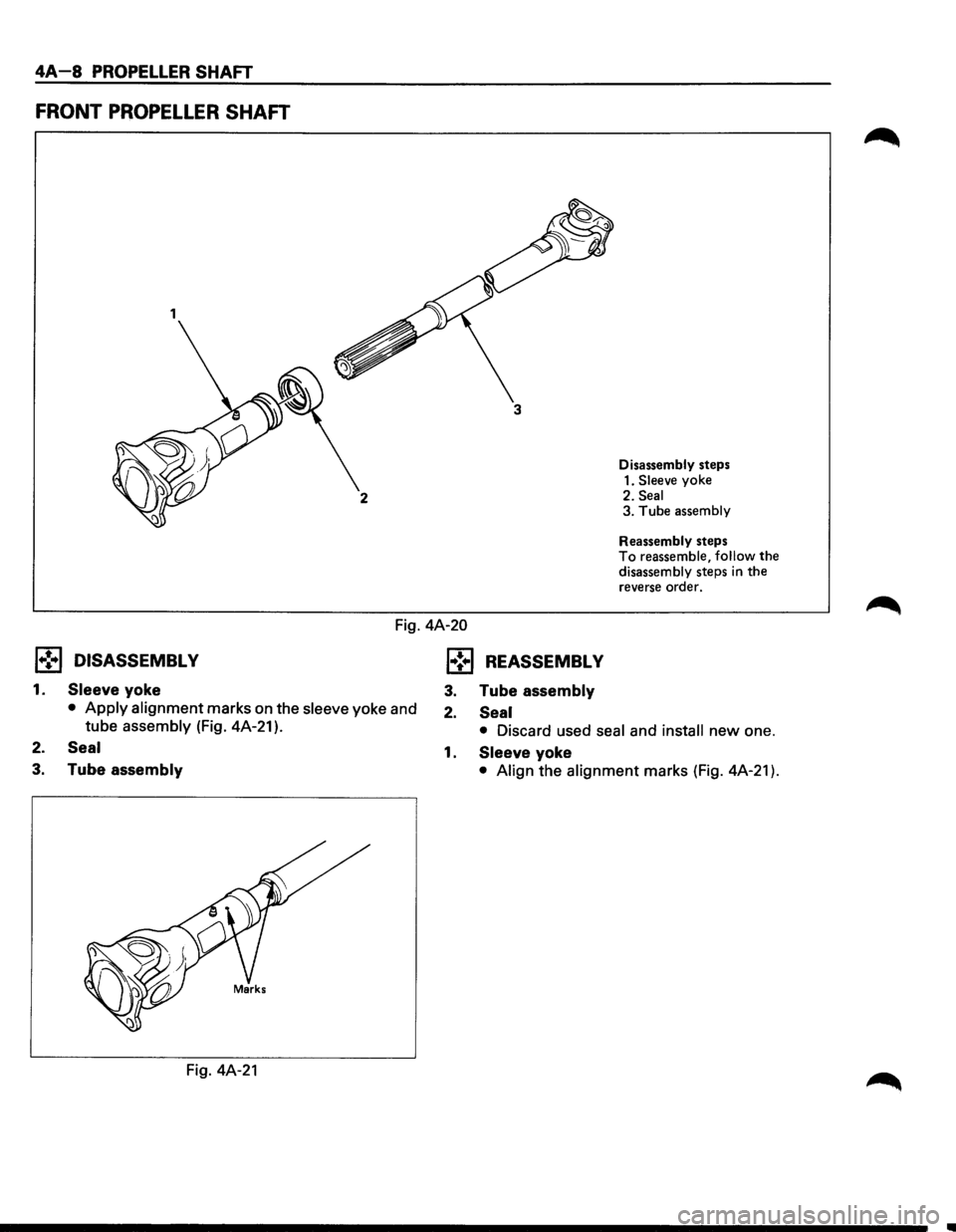
FRONT PROPELLER SHAFT
1
3
2
Disassembly steps
1.
Sleeve yoke
2. Seal 3. Tube assembly
Reassembly
steps To reassemble, follow the disassembly steps in the reverse order.
Fig. 4A-20
l•!•l DISASSEMBLY
1. Sleeve yoke
• Apply alignment marks on the sleeve yoke and
tube
assembly (Fig. 4A-21 ).
2. Seal
3. Tube assembly
Fig. 4A-21
l•!•l REASSEMBLY
3. Tube assembly
2. Seal
• Discard used seal and install new one.
1. Sleeve yoke
• Align the alignment marks (Fig. 4A-21 ).
Page 237 of 1928
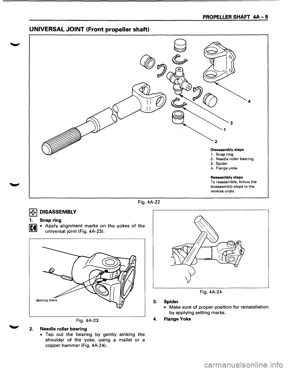
UNIVERSAL JOINT (Front propeller shaft)
PROPELLER SHAFT 4A-9
4
Disassembly steps
1. Snap ring 2. Needle roller bearing
3. Spider 4. Flange yoke
Reassembly steps
To reassemble, follow the
disassembly steps in the
reverse order.
Fig. 4A-22
l•!•l DISASSEMBLY
1. Snap ring
~ • Apply alignment marks on the yokes of the
~ universal joint (Fig. 4A-23).
Fig. 4A-23
2. Needle roller bearing
• Tap out the bearing by gently striking the
shoulder of the yoke, using a mallet or a
copper
hammer (Fig. 4A-24). Fig.
4A-24
3. Spider
• Make sure of proper position for reinstallation
by applying setting marks.
4. Flange
Yoke
Page 238 of 1928
4A -10 PROPELLER SHAFT
I L•IINSPECTION AND REPAIR
Make necessary correction or parts replacement if
wear, damage,corrosion or any other abnormal
condition is found through inspection.
NOTE:
When any part of the journal assembly (spider,
needle roller bearing) requires replacement, be sure
to replace the entire assembly.
Visual Check
Check the following parts for wear, damage, noise or
any other abnormal conditions.
• Spider
• Needle roller bearing
• Yoke
• Flange
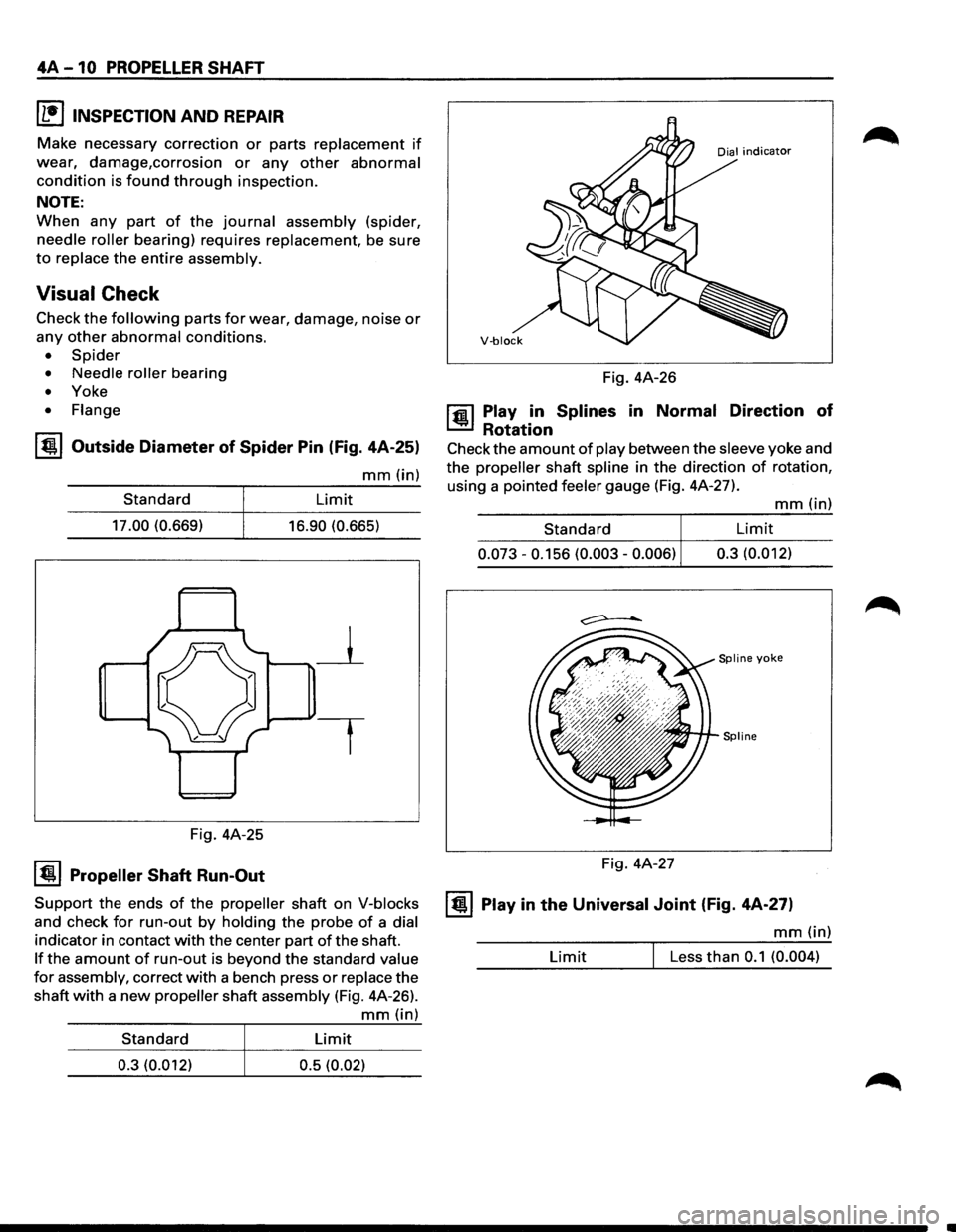
I til!, I Outside Diameter of Spider Pin (Fig. 4A-25)
mm(in)
Standard
17.00 (0.669)
Fig. 4A-25
I til!. I Propeller Shaft Run-Out
Limit
16.90 (0.665)
Support the ends of the propeller shaft on V-blocks
and check for run-out by holding the probe of a dial
indicator in contact with the center part of the shaft.
If the amount of run-out is beyond the standard value
for assembly, correct with a bench press or replace the
shaft
with a new propeller shaft assembly (Fig. 4A-26).
mm(in)
Standard Limit
0.3 (0.012)
0.5 (0.02)
V·block
Fig. 4A-26
1 til!, 1 Play in Splines in Normal Direction of
Rotation
Check the amount of play between the sleeve yoke and
the
propeller shaft spline in the direction of rotation,
using a pointed
feeler gauge (Fig. 4A-27).
mm (in)
Standard
Limit
0.073 - 0.156 (0.003 -0.006) 0.3 (0.012)
Spline yoke
Fig.
4A-27
ltil!.l Play in the Universal Joint (Fig. 4A-27)
mm (in)
Limit Less than 0.1 (0.004)
Page 239 of 1928
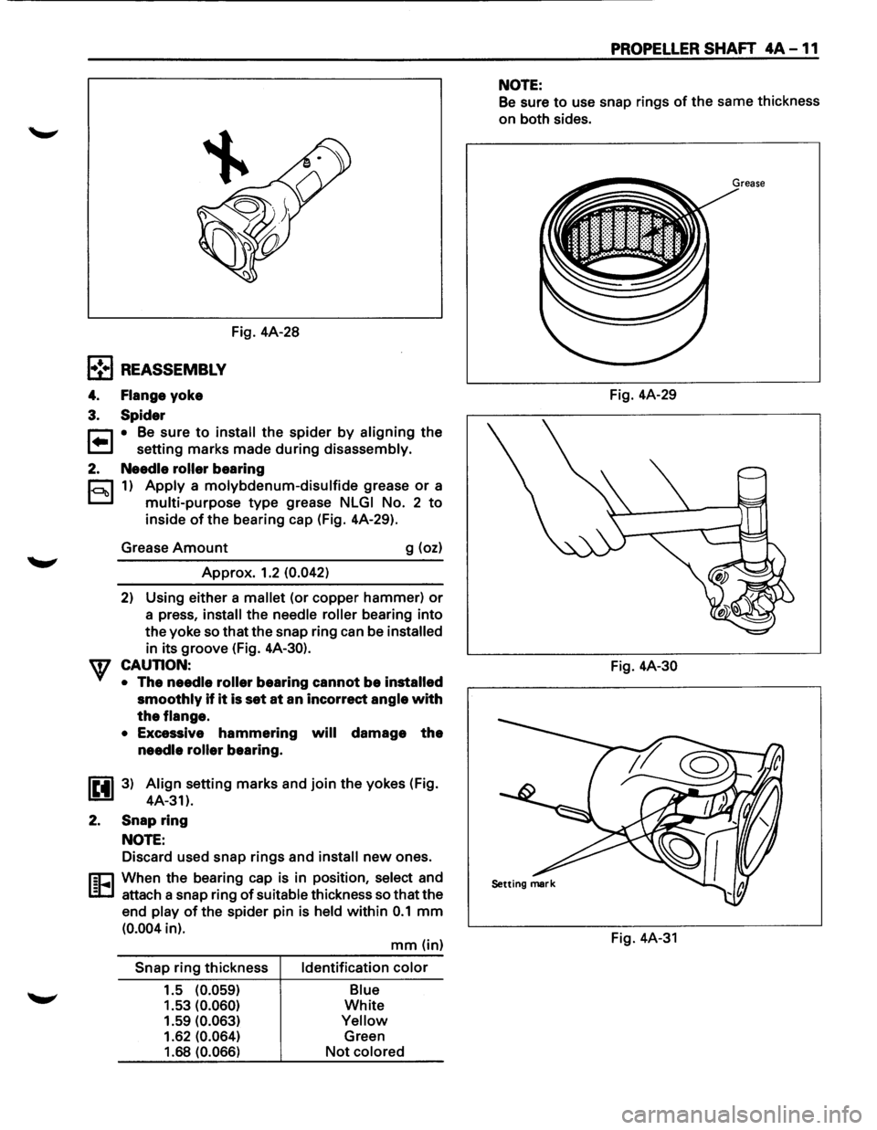
l•!•l REASSEMBLY
4. Flange yoke
3. Spider
Fig. 4A-28
r::1 • Be sure to install the spider by aligning the
t=J setting marks made during disassembly.
2. Needle roller bearing
c::::1 1) Apply a molybdenum-disulfide grease or a
D multi-purpose type grease NLGI No. 2 to
inside of the bearing cap (Fig. 4A-29).
Grease
Amount g (oz)
Approx. 1.2 (0.042)
2) Using either a mallet (or copper hammer) or
a press, install the needle roller bearing into
the yoke so that the snap ring can be installed
in its groove (Fig. 4A-30).
CAUTION: •
The needle roller bearing cannot be installed
smoothly if it is set at an incorrect angle with
the flange.
•
Excessive hammering will damage the
needle roller bearing.
IP.il 3) Align setting marks and join the yokes (Fig.
1!!!.1 4A-31).
2.
Snap ring
NOTE:
Discard used snap rings and install new ones.
rn:1 When the bearing cap is in position, select and
l:cJ attach a snap ring of suitable thickness so that the
end
play of the spider pin is held within 0.1 mm
(0.004 in).
Snap ring thickness
1.5
(0.059)
1.53 (0.060)
1.59 (0.063)
1.62 (0.064)
1.68 (0.066)
mm (in)
Identification color
Blue
White
Yellow
Green
Not colored
PROPELLER SHAFT 4A -11
NOTE:
Be sure to use snap rings of the same thickness
on both sides.
Fig. 4A-29
Fig.
4A-30
Fig. 4A-31
Page 240 of 1928
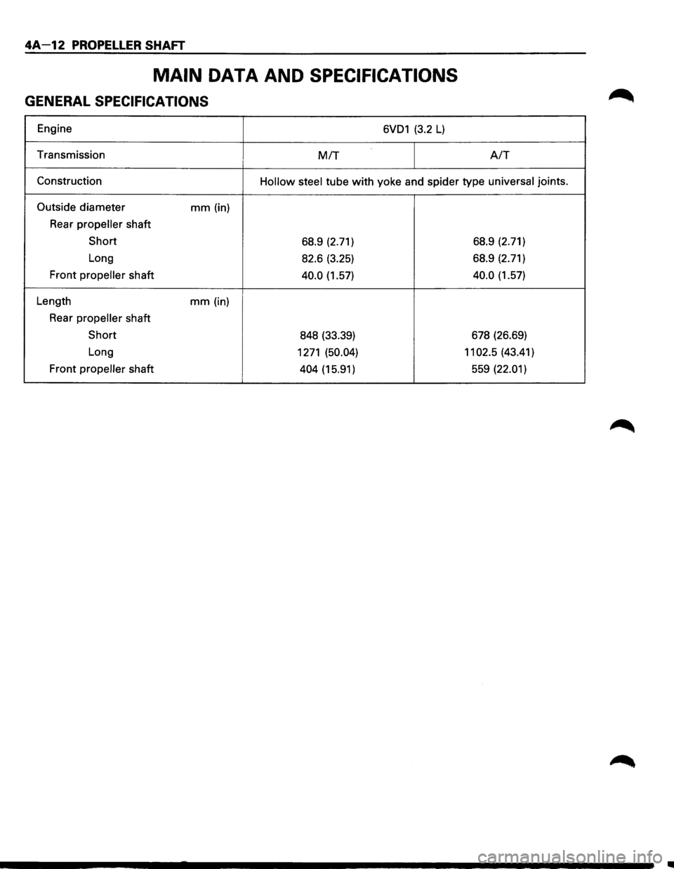
4A-12 PROPELLER SHAFT
MAIN DATA AND SPECIFICATIONS
GENERAL SPECIFICATIONS
Engine 6VD1 (3.2 L)
Transmission MIT A/T
Construction Hollow steel tube with yoke and spider type universal joints.
Outside diameter mm (in)
Rear
propeller shaft
Short 68.9 (2.71) 68.9
(2.71)
Long 82.6 (3.25) 68.9
(2.71)
Front
propeller shaft 40.0 (1.57) 40.0 (1.57)
Length
mm (in)
Rear
propeller shaft
Short 848 (33.39) 678
(26.69)
Long
1271 (50.04) 11 02.5 (43.41)
Front
propeller shaft 404 (15.91) 559 (22.01)
..