sensor ISUZU TROOPER 1995 Workshop Manual
[x] Cancel search | Manufacturer: ISUZU, Model Year: 1995, Model line: TROOPER, Model: ISUZU TROOPER 1995Pages: 1928
Page 883 of 1928

AUTOMATIC TRANSMISSION (4L30-E) 7 A-11
FUNCTIONS OF INPUT /OUTPUT COMPONENTS
Components Function
Speed sensor
Senses rotation
of output shaft and feeds the data to Transmission
(fixed
to transmission (T/M)) Control Module (TCM)
Throttle Senses the extent of throttle valve opening and the speed of the throttle
position sensor (TPS) valve lever motion to open the valve and feeds the data to TCM (fed to
(fixed to engine)
Engine Control Module (ECM) also)
I
Brake Switch (SW) Senses whether the driver has pressed the brake pedal or not and feeds
N (fixed
to brake pedal) the
information to TCM
p Kick-down SW (fixed to Senses whether the driver has pushed the accelerator pedal fully or not
u accelerator pedal) and feeds the information to TCM
T Mode
SW (fixed to T/M) Senses the select lever position and feeds the information to TCM
s Power drive SW Senses whether the driver has selected the power mode and feeds the
I (fixed to front console) information to TCM
G T/M
oil temp. sensor
Senses the T/M oil temperature and feeds the data to TCM
N Engine
coolant Senses the engine cooling water temperature and feeds the data to TCM
A temperature
SW (feeds the signal from ECM)
L
Engine speed
signal Feeds the signals monitoring engine speed to TCM from Ignition Control
Module
(fed to ECM also)
Air conditioning Senses whether the air conditioner has been switched on or not and
information feeds the information
to TCM
On-board diagnostic
input By monitoring the Ground (GND), the location of failure is shown on the
T/M
monitor lamp ("CHECK TRANS") by flashing the diagnostic trouble
code
Winter switch
Senses whether the driver has selected the winter mode, and feeds the
(fixed
to front console) information to TCM
Cruise
controller Downshift takes place when Overdrive OFF signal is received from auto
(Overdrive
OFF signal) cruise control unit
Shift
solenoid Selects shift point and gear position suited to the vehicle running con-s 1-2/3-4, 2-3
dition on the basis of TCM output 0 Band apply solenoid
Controls oil flow suited to the vehicle running condition on the basis of L
E TCM output
0 N
Torque
Converter Controls clutch engagement/disengagement suited to the vehicle
u 0 Clutch solenoid running condition on the basis of TCM output
T I Force motor Adjusts the oil pump delivery pressure to line pressure suited to the p D
(Pressure regulator vehicle running condition on the basis of TCM output u valve) T
Power drive mode lamp
Informs the driver whether the vehicle is in power mode or not
s Winter drive mode lamp Informs the driver whether the vehicle is in winter mode or not
I T/M monitor lamp Informs the driver of failure in the system. It also displays the self diagnosis
G
("CHECK TRANS") code.
N Data Link Connector
(DLC) When connected with TECH 1 or tester, can communicate the data for A
L function
check, etc. (fed to ECM also). When TECH 1 is not connected, can
communicate the
signal for torque management with ECM.
Self-diagnosis connector
When short-circuited with the bipolar connector, the T/M monitor lamp
displays
a failure by code.
ATF warning
lamp Lights when ATF oil temperature rises.
ABS signal When the select lever is at "Reverse" or "L" range, sends a signal to the
ABS controller as one of the ABS control conditions.
Page 905 of 1928
AUTOMATIC TRANSMISSION (4L30·E) 7 A-33
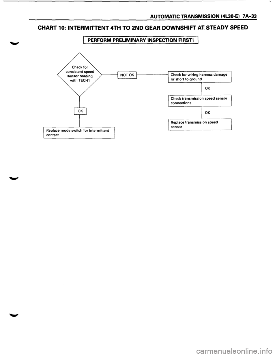
CHART 10: INTERMITTENT 4TH TO 2ND GEAR DOWNSHIFT AT. STEADY SPEED
PERFORM PRELIMINARY INSPECTION FIRST!
Check for consistent speed
sensor reading
with TECH1
Replace mode switch for intermittent
contact
1-------1 Check for wiring harness damage L...------1 or short to ground
OK
Check transmission speed sensor
connections
OK
Replace transmission speed
sensor
Page 909 of 1928
w CJ s: a: w Cl)
w ..... CJ :E w > I z 0
AUTOMATIC TRANSMISSION (4L30..E) 7 A-37
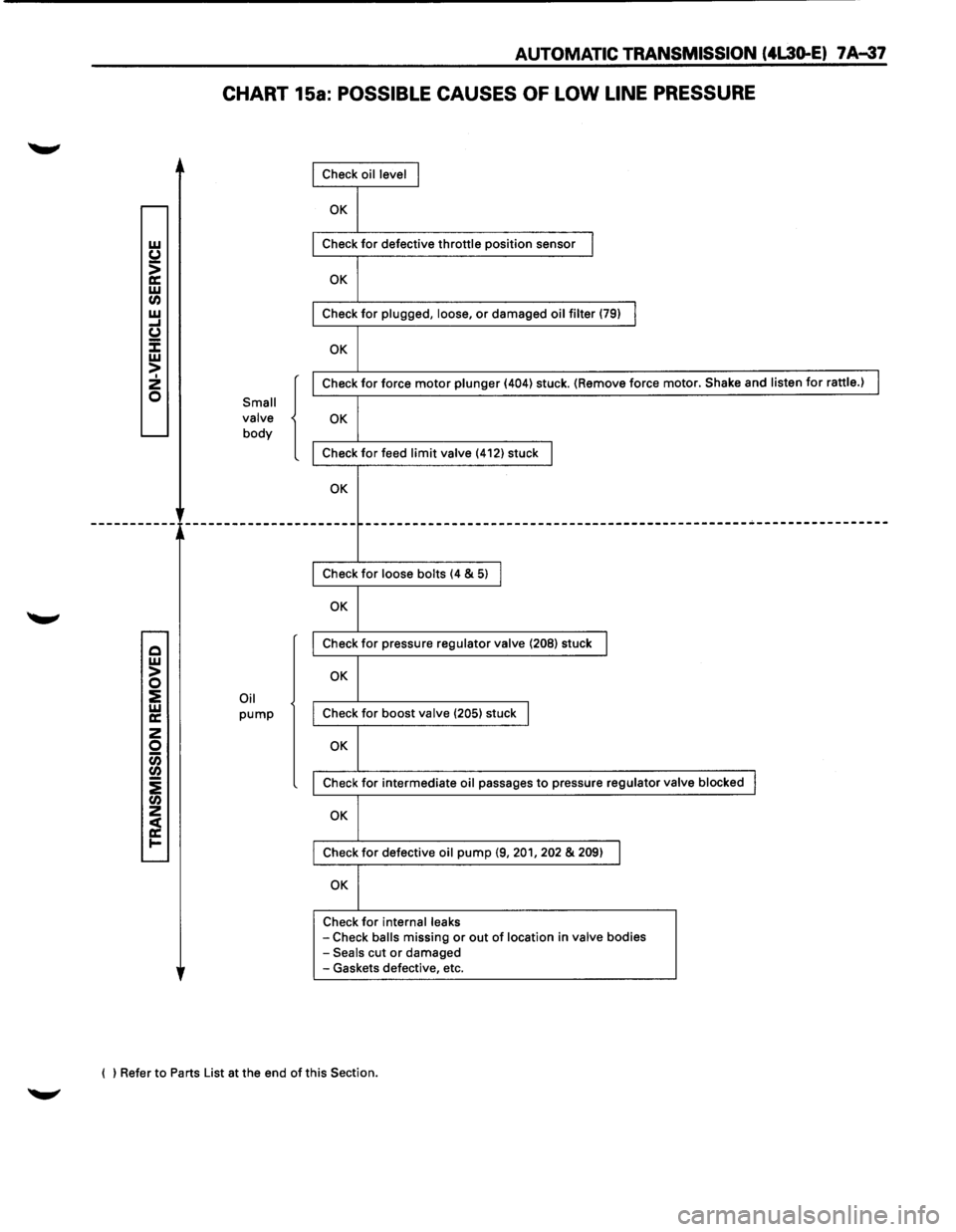
CHART 15a: POSSIBLE CAUSES OF LOW LINE PRESSURE
Small
valve
body
Oil pump
{
Check oil level I
OK
Check for defective throttle position sensor I
OK
Check for plugged, loose, or damaged oil filter (79) I
OK
Check for force motor plunger (404) stuck. (Remove force motor. Shake and listen for rattle.) I
OK
Check for feed limit valve (412) stuck I
OK
------------------------------------------------------------------------
Check for loose bolts (4 & 5) I
OK
Check for pressure regulator valve (208) stuck I
OK
Check for boost valve (205) stuck I
OK
Check for intermediate oil passages to pressure regulator valve blocked I
OK
Check for defective oil pump (9, 201, 202 & 209) I
OK
Check for internal leaks -Check balls missing or out of location in valve bodies -Seals cut or damaged
-Gaskets defective, etc.
( ) Refer to Parts List at the end
of this Section.
Page 910 of 1928
7 A-38 AUTOMATIC TRANSMISSION (4L30-E)
w (J
> a: w (I) w .... u :E w > I 2 0
Q w > 0 ::E w a:
2 0 CiS (I)
i (I) 2
~ .....
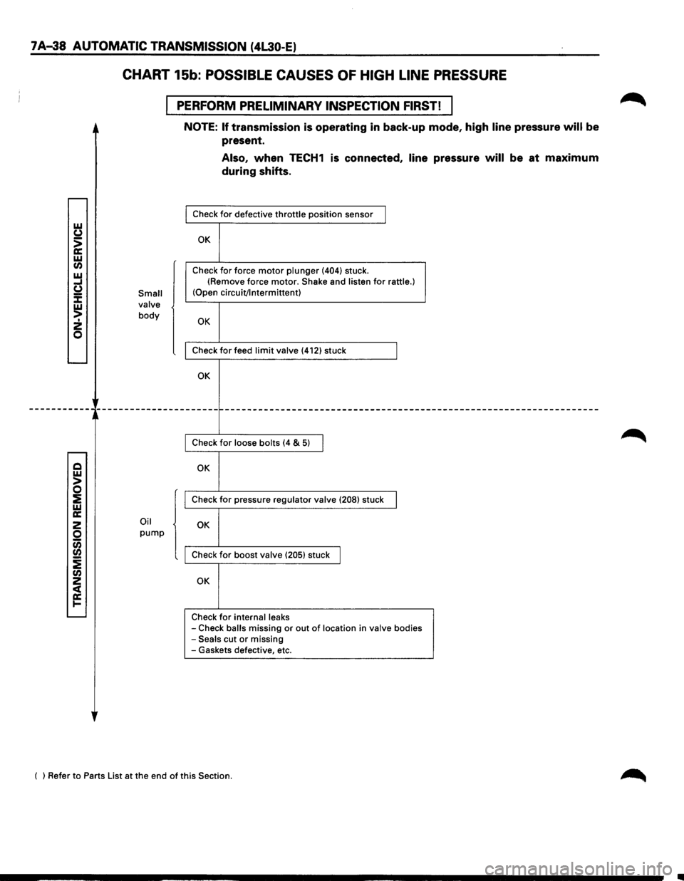
CHART 15b: POSSIBLE CAUSES OF HIGH LINE PRESSURE
PERFORM PRELIMINARY INSPECTION FIRST! I
Small
valve
body
Oil
pump
NOTE: If transmission is operating in back-up mode, high line pressure will be
present.
Also, when TECH1 is connected, line pressure will be at maximum
during shifts.
Check for defective throttle position sensor I
OK
Check for force motor plunger (404) stuck.
(Remove force motor. Shake and listen for rattle.) (Open circuit/Intermittent)
OK
Check for feed limit valve (412) stuck I
OK
--------------------------------------------
Check for loose bolts (4 & 5) I
OK
Check for pressure regulator valve (208) stuck I
OK
Check for boost valve (205) stuck I
OK
Check for internal leaks
-Check balls missing or out of location in valve bodies -Seals cut or missing
-Gaskets defective, etc.
( ) Refer to Parts List at the end
of this Section.
Page 912 of 1928
7 A-40 AUTOMATIC TRANSMISSION (4L30-E)
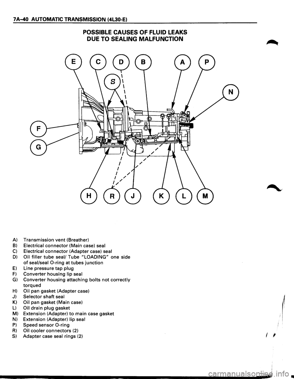
POSSIBLE CAUSES OF FLUID LEAKS
DUE
TO SEALING MALFUNCTION
A) Transmission vent (Breather)
B) Electrical connector (Main case) seal
C) Electrical connector (Adapter case) seal
D) Oil filler tube seal/ Tube "LOADING" one side
of seal/seal 0-ring at tubes junction
E) Line pressure tap plug
F) Converter housing lip seal
G) Converter housing attaching bolts not correctly
torqued
H) Oil pan gasket (Adapter case)
J) Selector shaft seal
Kl
Oil pan gasket (Main case)
L) Oil drain plug gasket
M) Extension (Adapter)
to main case gasket
Nl Extension (Adapter) lip seal
P) Speed sensor 0-ring
R) Oil cooler connectors (2)
S) Adapter case seal rings (2)
~·
I '
..
Page 919 of 1928
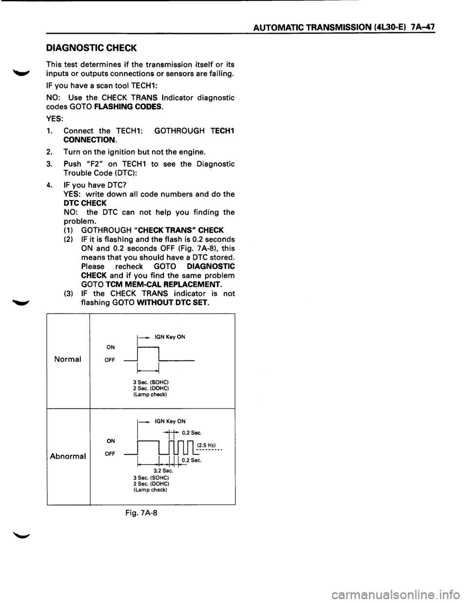
DIAGNOSTIC CHECK
This test determines if the transmission itself or its
~ inputs or outputs connections or sensors are failing.
IF you have a scan tool TECH1:
NO: Use the CHECK TRANS Indicator diagnostic
codes
GOTO FLASHING CODES.
YES:
1. Connect the TECH1: GOTHROUGH TECH1
CONNECTION.
2. Turn on the ignition but not the engine.
3. Push "F2" on TECH1 to see the Diagnostic
Trouble Code (OTC):
4. IF you have DTC?
YES: write down all code numbers and do the
DTCCHECK
NO: the DTC can not help you finding the
problem.
(1) GOTHROUGH "CHECK TRANS" CHECK
(2) IF it is flashing and the flash is 0.2 seconds
ON and 0.2 seconds OFF (Fig. 7A-8), this
means that you
should have a DTC stored.
Please recheck GOTO DIAGNOSTIC
CHECK and if you find the same problem
GOTO
TCM MEM-CAL REPLACEMENT.
(3) IF the CHECK TRANS indicator is not
........,. flashing GOTO WITHOUT DTC SET.
ON
~-IGNKeyON
__fL__ Normal OFF
w
3 Sec. (SOHC) 2 Sec. (DOHC} (Lamp check)
~-IGNKeyON
ON
~~ 0.2Sec.
~~~5-~=~--
Abnormal OFF
I. I Ill 0.2 Sec. I I I I I 3.2 Sec. 3 Sec. (SOHC) 2 Sec. (DOHC) (Lamp check}
Fig. 7A-8
AUTOMATIC TRANSMISSION (4L30-E) 7 A-47
Page 925 of 1928
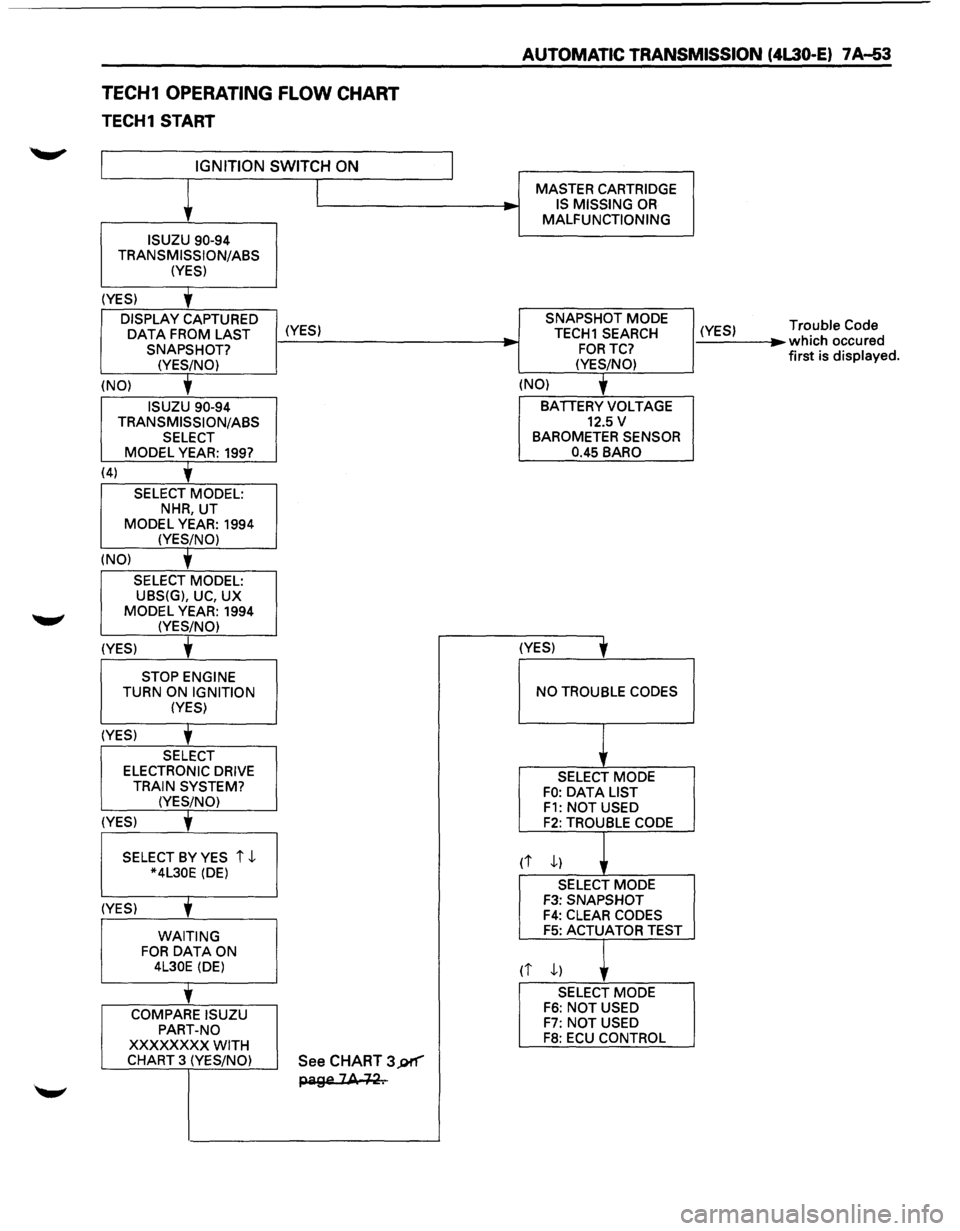
TECH1 OPERATING FLOW CHART
TECH1 START
IGNITION SWITCH ON
ISUZU 90-94
TRANSMISSION/ASS (YES)
(YES)
'
DISPLAY CAPTURED
OAT A FROM LAST (YES) SNAPSHOT?
(YES/NO)
(NO)
'
ISUZU 90-94
TRANSMISSION/ASS SELECT MODEL YEAR: 199?
(4)
'
SELECT MODEL: NHR, UT
MODEL YEAR: 1994 (YES/NO)
(NO)
'
SELECT MODEL: UBS(G), UC, UX
MODEL YEAR: 1994 (YES/NO)
(YES) t
STOP ENGINE TURN ON IGNITION (YES)
(YES)
'
SELECT ELECTRONIC DRIVE
TRAIN SYSTEM? (YES/NO)
(YES)
' SELECT BY YES i ,J.. *4L30E (DE)
(YES)
' WAITING FOR DATA ON 4L30E (DE)
'
COMPARE ISUZU
PART-NO
XXXXXXXX WITH CHART 3 (YES/NO) See CHART 3J)f"'"'"
page 2A +~.
__, -
AUTOMATIC TRANSMISSION (4L30-E) 7 A-53
MASTER CARTRIDGE
IS MISSING OR MALFUNCTIONING
SNAPSHOT MODE
TECH1 SEARCH
FORTC?
(YES/NO)
(NO)
'
BATIERY VOLTAGE 12.5 v BAROMETER SENSOR
0.45 BARO
(YES)
' NO TROUBLE CODES
SELECT MODE FO: OAT A LIST F1: NOT USED F2: TROUBLE CODE
rt ,J..)
SELECT MODE F3: SNAPSHOT F4: CLEAR CODES F5: ACTUATOR TEST
(i ,J..) ,
SELECT MODE F6: NOT USED F7: NOT USED F8: ECU CONTROL
(YES) ...
Trouble Code which occured
first is displayed.
Page 926 of 1928
7A-54 AUTOMATIC TRANSMISSION (4L30-E)
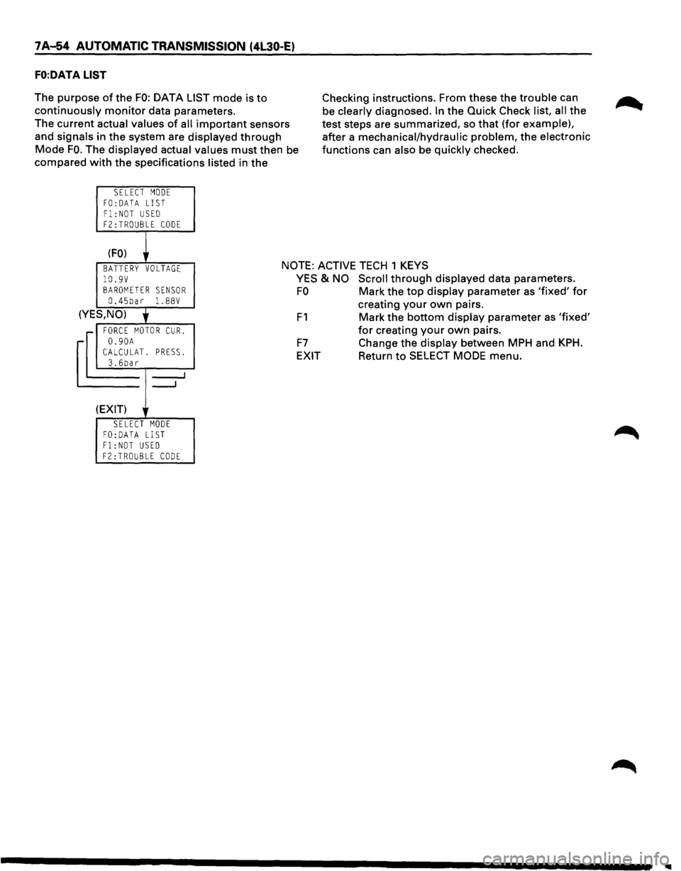
FO:DATA LIST
The purpose of the FO: DATA LIST mode is to
continuously monitor data parameters.
The current actual values
of all important sensors
and signals in the system are displayed
through
Mode FO. The displayed actual values must then be
compared
with the specifications listed in the
SELECT MODE
FO: DATA LIST Fl:NOT USED F2:TROUBLE CODE
(FO) r
Checking instructions. From these the trouble can
be clearly diagnosed.
In the Quick Check list, all the
test steps are summarized, so
that (for example),
after a mechanical/hydraulic problem, the electronic
functions can also be quickly checked.
BATTERY VOLTAGE NOTE: ACTIVE TECH 1 KEYS
10.9V BAROMETER SENSOR 0.45bar 1. 88V
(YES,NO)
' r FORCE MOTOR CUR.
-0.90A CALCULAT. PRESS. 3.6bar
_....J
---'
(EXIT)
SELECT MODE FO:DATA LIST Fl:NOT USED F2:TROUBLE CODE
YES & NO Scroll through displayed data parameters.
FO Mark the top display parameter as 'fixed' for
F1
F7
EXIT
creating your own pairs.
Mark the bottom display parameter as 'fixed'
for creating your own pairs.
Change the display between MPH and
KPH.
Return to SELECT MODE menu.
Page 929 of 1928
AUTOMATIC TRANSMISSION (4l30·E) 7 A-57
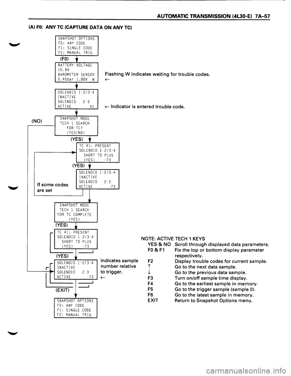
(A) FO: ANY TC (CAPTURE DATA ON ANY TC)
SNAPSHOT OPTIONS FO: ANY CODE
F1: SINGLE CODE F2: MANUAL TRIG
(FO) + BATTERY VOLTAGE 10.9V
BAROMETER SENSOR Flash in g W indicates waiting for trouble codes.
0.45bar l.BBV w ~
'
SOLENOID 1-2/3-4
INACTIVE SOLENOID 2-3 ACTIVE 41 ~lndi cator is entered trouble code.
+
(NO) SNAPSHOT MODE TECH 1 SEARCH FOR TC? (YES/NO)
(YES)
'
TC 41: PRESENT SOLENOID 1-2/3-4 SHORT TO PLUS (YES) -73
(YES) y
SOLENOID 1-2/3-4 INACTIVE
If some codes SOLENOID 2-3 ACT! VE -73 are set I
SNAPSHOT MODE
TECH 1 SEARCH FOR TC COMPLETE (YES)
(YES)
• TC 41: PRESENT SOLENOID 1-2/3-4
SHORT TO PLUS (YES) -73
(YES)
.[ SOLENOID 1-2/3-4 Indicates sample
relative
r. r INACTIVE number
~0
2-3 to trigge
E -73 ~
_J (EXIT) lr
SNAPSHOT OPTIONS FO: ANY CODE F1: SINGLE CODE F2: MANUAL TRIG
NOTE: ACTIVE TECH 1 KEYS
YES
& NO Scroll through displayed data parameters.
FO & F1 Fix the top or bottom display parameter
F2
i j,
F3
F4
FS
F6
EXIT respectively.
Display trouble
codes for current sample.
Go to the next data sample.
Go to the previous data sample.
Turn on/off sample time display.
Go to the earliest sample in memory.
Go to the trigger sample (sample 0).
Go to the latest sample in memory.
Return to Snapshot Options menu.
Page 931 of 1928
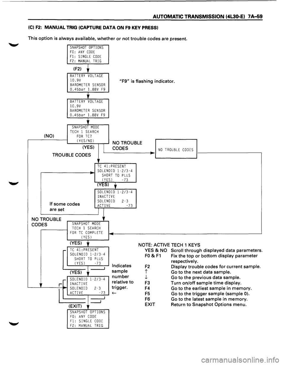
AUTOMATIC TRANSMISSION (4l30-E) 7A-59
(C) F2: MANUAL TRIG (CAPTURE DATA ON F9 KEY PRESS)
This option is always available, whether or not trouble codes are present.
SNAPSHOT OPTIONS FO: ANY CODE Fl: SINGLE CODE F2: MANUAL TRIG
(F2)
BATTERY VOLTAGE
10.9V BAROMETER SENSOR 0.45bar 1.88V F9
"F9" is flashing indicator.
'
BATTERY VOLTAGE 10.9V BAROMETER SENSOR 0.45bar 1.88V F9
j_
SNAPSHOT MODE TECH 1 SEARCH (NO) FOR TC?
CYES/NOl
(YES)
TROUBLE CODES
NO TROUBLE
CODES
TC 41:PRESENT
.----------~· SOLENOID 1-2/3-4 SHORT TO PLUS
CYESl -73
(YES) y
SOLENOID 1-2/3-4
INACTIVE
If some codes
are set SOLENOID 2-3 ACTIVE -73
NO TROUBLE
CODES SNAPSHOT MODE
TECH 1 SEARCH FOR TC COMPLETE CYESl
NO TROUBLE CODES ..
(YES) j NOTE: ACTIVE TECH 1 KEYS r-TC 41: PRESENT SOLENOID 1-2/3-4
SHORT TO PLUS CYESl -73 I Indicates
(YES)
sample
r--~~:--":'"~~ number
r[ i~~g~0~ 1 -2
/3
-4 relative
to
'---...L----=--
1
~ soLEN~ I-D r-------l-2 _-~...;.7.;;..3 1
__, ~gger.
(EXIT)
SNAPSHOT OPTIONS FO: ANY CODE Fl: SINGLE CODE F2: MANUAL TRIG
YES & NO Scroll through displayed data parameters.
FO & F1 Fix the top or bottom display parameter
F2
I
J,
F3
F4
F5
F6
EXIT
respectively.
Display trouble codes for current sample.
Go to the next data sample.
Go to the previous data sample.
Turn
on/off sample time display.
Go to the earliest sample in memory.
Go to the trigger sample (sample 0).
Go to the latest sample in memory.
Return to Snapshot Options menu.