sensor ISUZU TROOPER 1995 Workshop Manual
[x] Cancel search | Manufacturer: ISUZU, Model Year: 1995, Model line: TROOPER, Model: ISUZU TROOPER 1995Pages: 1928
Page 1047 of 1928
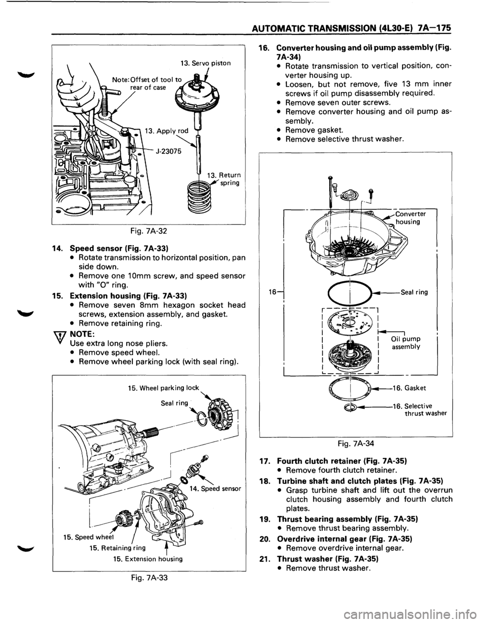
13. Servo piston
Fig. 7A-32
14. Speed sensor (Fig. 7A-33)
• Rotate transmission to horizontal position, pan
side down.
• Remove one 1 Omm screw, and speed sensor
with "0" ring.
15. Extension housing (Fig. 7 A-33)
• Remove seven 8mm hexagon socket head
screws, extension assembly, and gasket.
• Remove retaining ring.
\fl NOTE:
V Use extra long nose pliers.
• Remove speed wheel.
• Remove wheel parking lock (with seal ring).
15. Wheel parking lock
Seal:~
15. Retaining ring
15. Extension housing
Fig. 7A-33
AUTOMATIC TRANSMISSION (4L30-E) 7A-175
16. Converter housing and oil pump assembly (Fig.
7A-34)
16
• Rotate transmission to vertical position, con
verter housing up.
• Loosen, but not remove, five 13 mm inner
screws
if oil pump disassembly required.
• Remove seven outer screws.
• Remove converter housing and oil pump as
sembly.
• Remove gasket.
• Remove selective thrust washer.
~---16. Selective thrust washer
Fig. 7A-34
17. Fourth clutch retainer (Fig. 7A-35)
• Remove fourth clutch retainer.
18. Turbine shaft and clutch plates (Fig. 7A-35)
• Grasp turbine shaft and lift out the overrun
clutch housing assembly and fourth
clutch
plates.
19. Thrust bearing assembly (Fig. 7A-35)
• Remove thrust bearing assembly.
20. Overdrive internal gear (Fig. 7A-35)
• Remove overdrive internal gear.
21. Thrust washer (Fig. 7A-35)
• Remove thrust washer.
Page 1057 of 1928
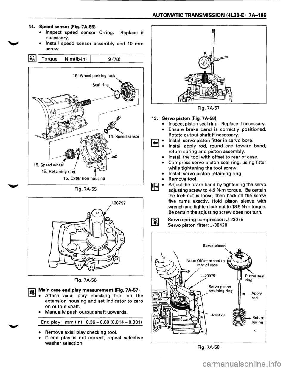
14. Speed sensor (Fig. 7A-55)
• Inspect speed sensor 0-ring. Replace if
necessary.
~ • Install speed sensor assembly and 10 mm
screw.
~~~ Torque N-m(lb-in) 9 (78)
15. Wheel parking lock
15. Retaining ring
15. Extension housing
Fig. 7A-55
J-36797
Fig. 7A-56
rfil Main case end play measurement (Fig. 7A-57)
~ • Attach axial play checking tool on the
extension housing and set indicator to zero
on
output shaft.
• Manually push output shaft upwards.
End play mm (in) 10.36-0.80 (0.014-0.031)
• Remove axial play checking tool.
• If end play is not correct, repeat selective
washer selection.
AUTOMATIC TRANSMISSION (4l30-E) 7A-185
Fig. 7A-57
13. Servo piston (Fig. 7A-58)
•
•
8:
•
•
•
•
[E•
Inspect piston seal ring. Replace if necessary .
Ensure brake band is correctly
positioned .
Rotate
output shaft if necessary.
Install servo piston fitter in servo bore.
Install apply rod, round end toward band,
return
spring and piston assembly.
Install the tool with offset to rear of case .
Compress servo
piston seal ring, using fitter
while tightening the tool screw.
Install servo piston retaining ring .
Remove
tool.
Adjust the brake band by tightening the servo
adjusting screw
to 4.5 N-m torque. Be certain
the lock nut
is loose, then back-off the screw
five turns exactly. Hold piston sleeve with
wrench and tighten lock nut to
18.5 N-m torque.
Be certain the adjusting screw does not turn.
Servo
spring compressor: J-23075
Servo piston fitter: J-38428
Servo piston
Note: Offset
of tool to rear of case
Servo piston
retaining ring
J-38428
Fig. 7A-58
~~--Return spring
Page 1086 of 1928
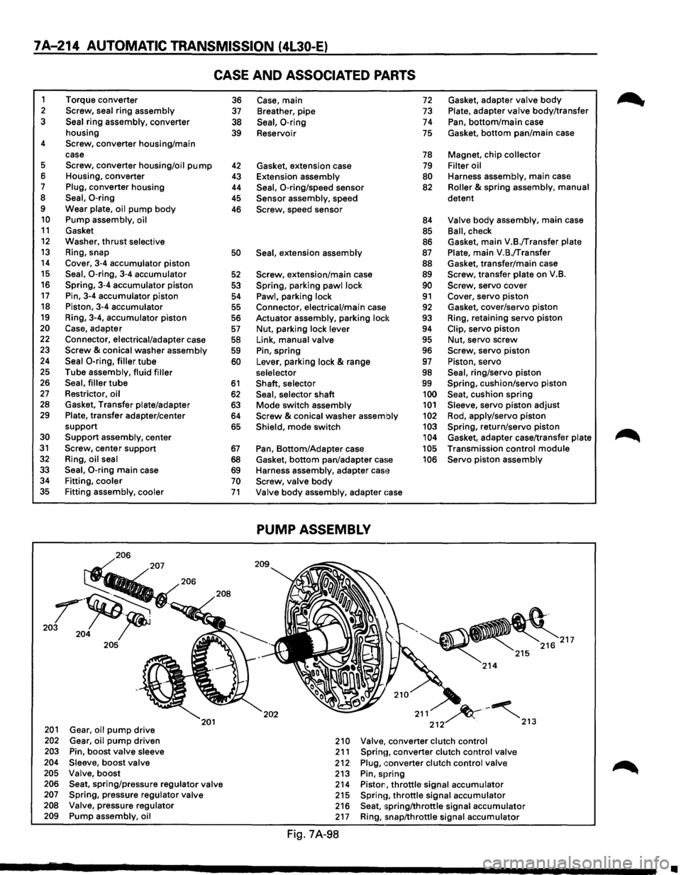
7A-214 AUTOMATIC TRANSMISSION (4L30-E)
CASE AND ASSOCIATED PARTS
1 Torque converter 2 Screw, seal ring assembly 3 Seal ring assembly, converter
housing
4 Screw, converter housing/main
case
5 Screw, converter housing/oil pump 6 Housing, converter 7 Plug, converter housing 8 Seal, 0-ring 9 Wear plate, oil pump body 10 Pump assembly, oil 11 Gasket 12 Washer, thrust selective 13 Ring, snap 14 Cover, 3-4 accumulator piston 15 Seal, 0-ring, 3-4 accumulator 16 Spring, 3-4 accumulator piston 17 Pin, 3-4 accumulator piston 18 Piston, 3-4 accumulator 19 Ring, 3-4, accumulator piston 20 Case, adapter 22 Connector, electrical/adapter case 23 Screw & conical washer assembly 24 Seal 0-ring, filler tube 25 Tube assembly, fluid filler 26 Seal, filler tube 27 Restrictor, oil 28 Gasket, Transfer plate/adapter 29 Plate, transfer adapter/center
support
30 Support assembly, center 31 Screw, center support 32 Ring, oil seal
33 Seal, 0-ring main case 34 Fitting, cooler 35 Fitting assembly, cooler
206
201 Gear, oil pump drive 202 Gear, oil pump driven 203 Pin, boost valve sleeve 204 Sleeve, boost valve 205 Valve, boost
201
206 Seat, spring/pressure regulator valve 207 Spring, pressure regulator valve 208 Valve, pressure regulator 209 Pump assembly, oil
36 37
38
39
42 43
44
45
46
50
52
53
54
55
56
57
58 59
60
61
62 63 64
65
67
68 69 70 71
Case, main 72 Gasket, adapter valve body
Breather, pipe 73 Plate, adapter valve body/transfer
Seal, 0-ring 74 Pan, bottom/main case
Reservoir
75 Gasket, bottom pan/main case
78 Magnet, chip collector
Gasket, extension case
79 Filter oil
Extension assembly
80 Harness assembly, main case
Seal, 0-ring/speed sensor 82 Roller & spring assembly, manual
Sensor assembly, speed detent Screw, speed
sensor 84 Valve body assembly, main case
85 Ball, check
86 Gasket, main V.B./Transfer plate
Seal, extension assembly 87 Plate, main V.B./Transfer
88 Gasket, transfer/main case
Screw, extension/main case 89 Screw, transfer plate on V.B.
Spring, parking pawl lock 90 Screw, servo cover
Pawl, parking lock 91 Cover, servo piston Connector, electrical/main case 92 Gasket, cover/servo piston
Actuator assembly, parking lock
93 Ring, retaining servo piston
Nut, parking lock lever 94 Clip, servo piston
Link, manual valve 95 Nut, servo screw
Pin, spring 96 Screw, servo piston
Lever, parking lock
& range 97 Piston, servo
selelector 98 Seal, ring/servo piston
Shaft, selector 99 Spring, cushion/servo piston
Seal, selector shaft 100 Seat, cushion spring
Mode switch assembly 101 Sleeve, servo piston adjust
Screw & conical washer assembly 102 Rod, apply/servo piston
Shield, mode switch 103 Spring, return/servo piston 104 Gasket, adapter case/transfer plate
Pan, Bottom/Adapter case 105 Transmission control module
Gasket,
bottom pan/adapter ca!~e 106 Servo piston assembly
Harness assembly, adapter
cas'~ Screw, valve body
Valve body assembly, adapter ~:ase
PUMP ASSEMBLY
202 211 ~-~ 212 . 213
210 Valve, converter clutch control 211 Sprinn, converter clutch control valve 212 Plug, converter clutch control valve 213 Pin, spring 214 Piston, throttle signal accumulator 215 Sprinn, throttle signal accumulator 216 Seat, 1;pring/throttle signal accumulator 217 Ring, snap/throttle signal accumulator
Fig. 7A-98
~
•
Page 1095 of 1928
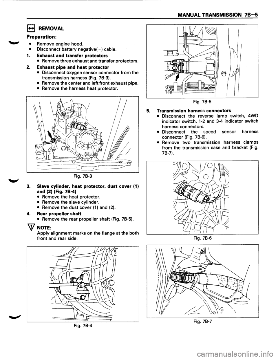
EJ REMOVAL
Preparation:
'--"' • Remove engine hood.
• Disconnect battery negative(-) cable.
1. Exhaust and transfer protectors
• Remove three exhaust and transfer protectors.
2. Exhaust pipe and heat protector
3.
• Disconnect oxygen sensor connector from the
transmission harness (Fig. 78-3).
• Remove the center and left front exhaust pipe.
• Remove the harness heat protector.
lj
Fig. 78-3
Slave cylinder, heat protector, dust cover (1)
and (2) (Fig. 78-4)
• Remove the heat protector.
• Remove the slave cylinder.
•
Remove the dust cover (1) and (2).
4. Rear propeller shaft
• Remove the rear propeller shaft (Fig. 78-5).
W NOTE:
Apply alignment marks on the flange at the both
front and rear side.
Fig. 78-4
MANUAL TRANSMISSION 78-5
Fig. 78-5
5. Transmission harness connectors
• Disconnect the reverse lamp switch, 4WD
indicator switch,
1-2 and 3-4 indicator switch
harness connectors.
• Disconnect the speed sensor harness
connector (Fig. 78-6).
• Remove two transmission harness clamps
from the transmission case and bracket (Fig.
78-7).
Fig. 78-6
Fig. 78-7
Page 1099 of 1928
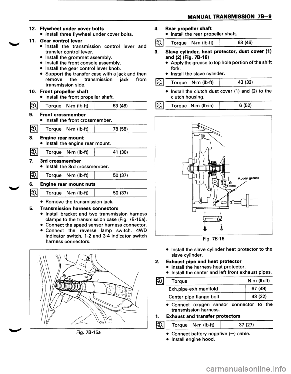
12. Flywheel under cover bolts
• Install
three flywheel under cover bolts.
11. Gear control lever
• Install
the transmission control lever and
transfer
control lever.
• Install
the grommet assembly.
• Install
the front console assembly.
• Install
the gear control lever knob.
• Support the transfer case with a jack and then
remove the transmission jack
from
transmission side.
10. Front propeller shaft
• Install the front propeller shaft.
~~~ Torque N·m (lb·ft) 63 (46)
9. Front crossmember
• Install the front crossmember.
~~~ Torque N·m (lb·ft) 78 (58)
8. Engine rear mount
• Install the engine rear mount.
~~~ Torque N·m (lb·ft) 41 (30)
7. 3rd crossmember
• Install the 3rd crossmember.
1~1 Torque N-m (lb·ft) 50 (37)
6. Engine rear mount nuts
~~~ Torque N-m (lb·ft) 50 (37)
• Remove the transmission jack.
5. Transmission harness connectors
• Install bracket and two transmission harness
clamps to the transmission case (Fig. 78-15a).
• Connect the speed sensor harness connector.
• Connect the reverse lamp switch, 4WD
indicator
switch, 1-2 and 3-4 indicator switch
harness connectors.
Fig. 78-15a
MANUAL TRANSMISSION 78-9
4. Rear propeller shaft
• Install the rear propeller shaft.
I~I __ T_o_rq~u_e __ N_·m~(_lb_·ft~)~ _____ 6_3~(_46~) ____ _
3. Slave cylinder. heat protector. dust cover (1)
and (2) (Fig. 78-16)
• Apply the grease to top hole portion of the shift
fork.
• Install the slave cylinder.
~~~ Torque N·m (lb·ft) I 43 (32) _..:....__~----
• Install the clutch dust cover (1) and (2) to the
clutch housing.
~~~ Torque N·m (lb·in) 6 (52)
Apply grease
Fig. 78-16
• Install the slave cylinder heat protector to the
slave cylinder.
2. Exhaust pipe and heat protector
• Install the harness heat protector.
• Install the center and left front exhaust pipes.
~~~ Torque
Exh.pipe-exh.manifold
Center pipe
flange bolt N·m
(lb·ft)
67 (49)
43 (32)
• Connect oxygen sensor connector to the
transmission harness.
1. Exhaust and transfer protectors
~~~ Torque N·m (lb·ft) 37 (27)
• Connect battery negative (-) cable.
• Install
engine hood.
Page 1102 of 1928
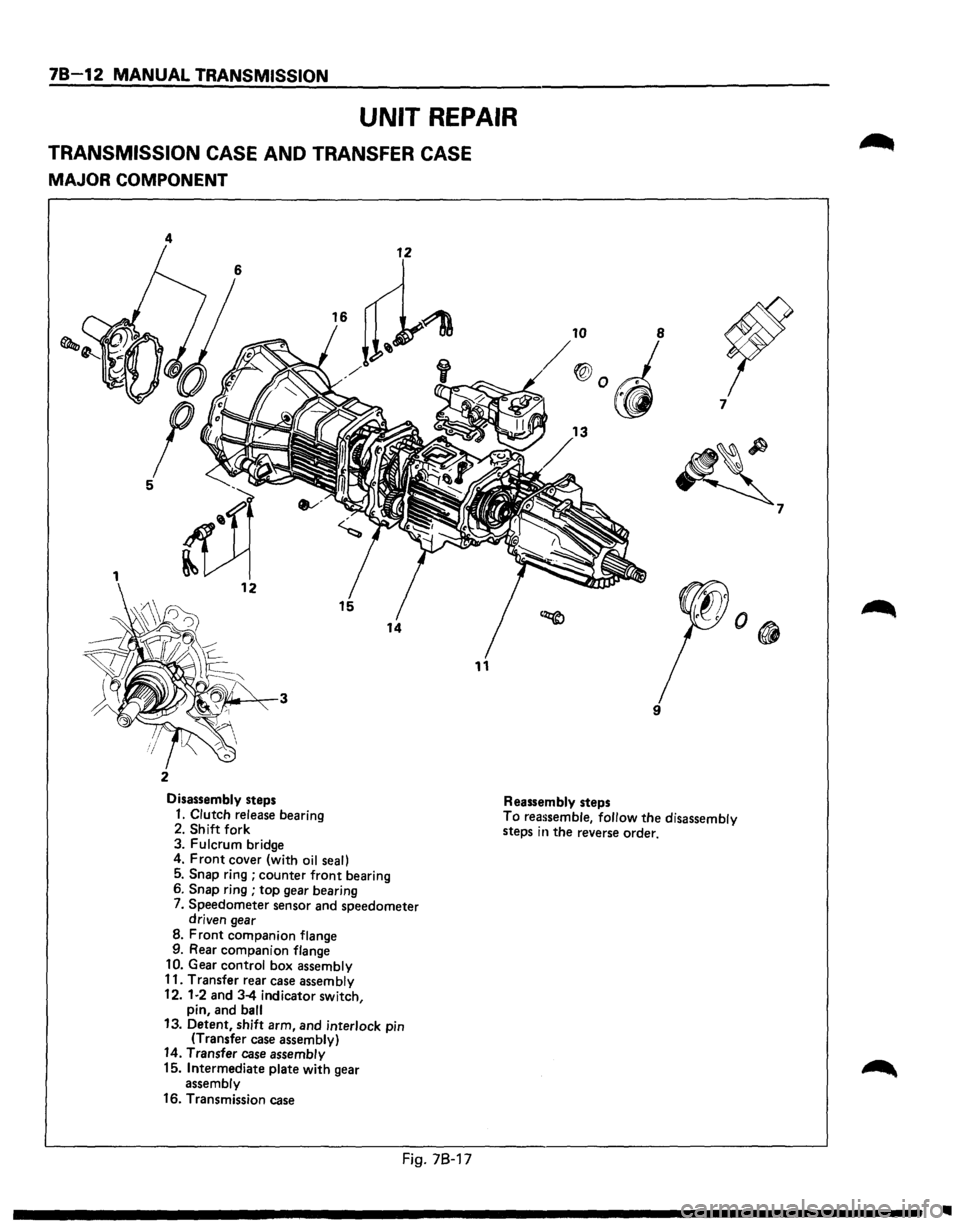
78-12 MANUAL TRANSMISSION
UNIT REPAIR
TRANSMISSION CASE AND TRANSFER CASE
MAJOR COMPONENT
4
11
2
Disassembly steps Reassembly steps 7
~
9
1. Clutch release
bearing 2. Shift fork
3. Fulcrum bridge To reassemble, follow the disassembly
steps in the reverse order.
4.
Front cover (with oil seal)
5. Snap ring ; counter front bearing
6. Snap ring ; top gear bearing
7. Speedometer sensor and speedometer
driven gear
8. Front companion flange
9. Rear companion flange
10. Gear control box assembly
11. Transfer rear case assembly
12.
1·2 and 3-4 indicator switch,
pin, and ball 13. Detent, shift arm, and interlock pin
(Transfer case assembly) 14. Transfer case assembly
15. Intermediate plate with gear
assembly
16. Transmission case
Fig. 78-17
7
Ill
Page 1103 of 1928
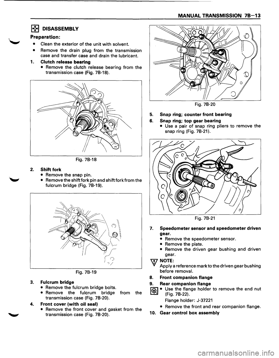
1•!,.1 DISASSEMBLY
Preparation:
• Clean the exterior of the unit with solvent.
•
Remove the drain plug from the transmission
case and transfer case and drain the
lubricant.
1. Clutch release bearing
• Remove the clutch release bearing from the
transmission case (Fig.
78-18).
Fig. 78-18
2. Shift fork
• Remove the snap pin.
''-" • Remove the shift fork pin and shift fork from the
fulcrum bridge (Fig. 78-19).
Fig. 78-19
3. Fulcrum bridge
• Remove the fulcrum bridge bolts.
•
Remove the fulcrum bridge from the
transmission case (Fig.
78-20).
4. Front cover (with oil seal)
• Remove the front cover and gasket from the
transmission case (Fig.
78-20).
MANUAL TRANSMISSION 78-13
Fig. 78-20
5. Snap ring; counter front bearing
6. Snap ring; top gear bearing
• Use a pair of snap ring pliers to remove the
snap ring (Fig.
78-21 ).
Fig. 78-21
1. Speedometer sensor and speedometer driven
gear.
• Remove the speedometer sensor.
• Remove the plate.
•
Remove the driven gear bushing and driven
gear.
'\fl NOTE:
VI Apply a reference mark to the driven gear bushing
before
removal.
8. Front companion flange
9. Rear companion flange
l'ia\1 • Use the flange holder to remove the end nut
~ (Fig. 78-22).
Flange holder: J-37221
• Remove the front and rear companion flange.
10. Gear control box assembly
Page 1106 of 1928
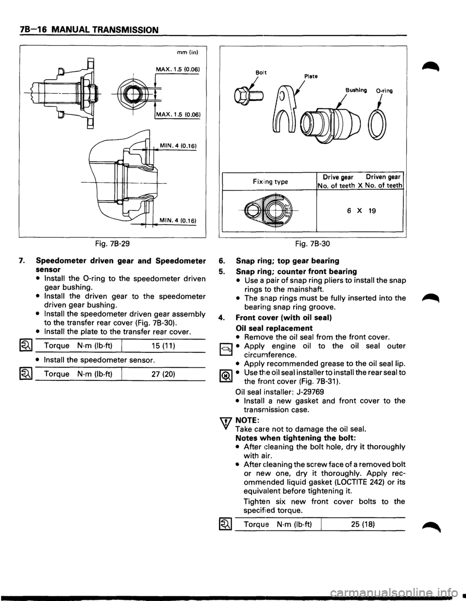
78-16 MANUAL TRANSMISSION
7.
mm{in)
MAX. 1.5 (0.06)
MAX. 1.5 10.06)
MIN. 4 (0.16)
MIN. 4 (0.16)
Fig. 78-29
Speedometer driven gear and Speedometer
sensor
• Install the 0-ring to the speedometer driven
gear bushing.
• Install the driven gear to the speedometer
driven gear bushing.
• Install the speedometer driven gear assembly
to the transfer rear cover (Fig. 78-30).
• Install the plate to the transfer rear cover.
l"i't I Torque N·m (lb·ft) ~ _...:.____---~... ___ _ 15 (11)
• Install the speedometer sensor.
I~I_T_o_rq...;_u_e_N_·_m_(_lb_·ft_l----~. ___ 2_7_(2_0_) __ _
Plate Bolt
~
Fix1ing type Drive gear Driven gear
No. of teeth
X No. of teeth
6 X 19
Fig. 78-30
6. Snap ring; top gear bearing
5. Snap ring; counter front bearing
• Use a pair of snap ring pliers to install the snap
rings to the mainshaft.
• The snap rings must be fully inserted into the
bearing snap ring groove.
4. Front cover (with oil seal)
Oil seal
replacement
• Remove the oil seal from the front cover.
c:::;J • Apply engine oil to the oil seal outer
D circumference.
• Apply recommended grease to the oil seal lip.
1®.1• Use the oil seal installer to install the rear seal to
the
front cover (Fig. 78-31 ).
Oil seal installer: J-29769
• Install a new gasket and front cover to the
transmission case.
'\f7 NOTE:
"+({ Take care not to damage the oil seal.
Notes when tightening the bolt:
• After Gleaning the bolt hole, dry it thoroughly
with air.
• After Gleaning the screw face of a removed bolt
or new one, dry it thoroughly. Apply rec
omme~nded liquid gasket (LOCTITE 242) or its
equivalent before tightening it.
Tighten six
new front cover bolts to the
specified torque.
1~1 Torque N·m (lb·ft) 25 (18)
..
Page 1161 of 1928
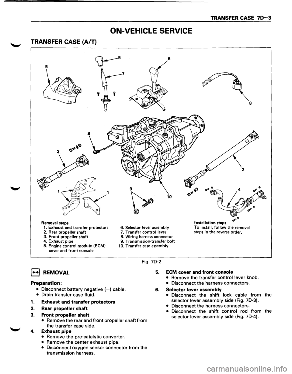
TRANSFER CASE 70-3
ON-VEHICLE SERVICE
TRANSFER CASE (A/T)
5
<;J---5 6
7
' 8
9
~
10
Removal steps Installation steps
1. Exhaust and transfer protectors 6. Selector lever
assembly To
install, follow the removal
steps in the reverse order.
2. Rear propeller shaft 7.
Transfer control lever
3. Front propeller shaft 8.
Wiring harness connector
4. Exhaust pipe 9. Transmission-transfer bolt
5. Engine control module
(ECM)
cover and front console 10.
Transfer case assembly
Fig. 7D-2
l••l REMOVAL
Preparation:
• Disconnect battery negative (-) cable.
•
Drain transfer case fluid.
1. Exhaust and transfer protectors
2. Rear propeller shaft
3. Front propeller shaft
• Remove the rear and front propeller shaft from
the transfer case side.
4. Exhaust pipe
• Remove the pre-catalytic converter.
• Remove the center exhaust pipe.
• Disconnect oxygen sensor connector from the
transmission harness.
5. ECM cover and front console
• Remove the transfer control lever knob.
• Disconnect the harness connectors.
6. Selector lever assembly
• Disconnect the shift lock cable from the
selector lever assembly side (Fig. 7D-3).
• Disconnect the harness connectors.
• Disconnect the shift control rod from the
selector lever assembly side (Fig. 7D-4).
Page 1162 of 1928
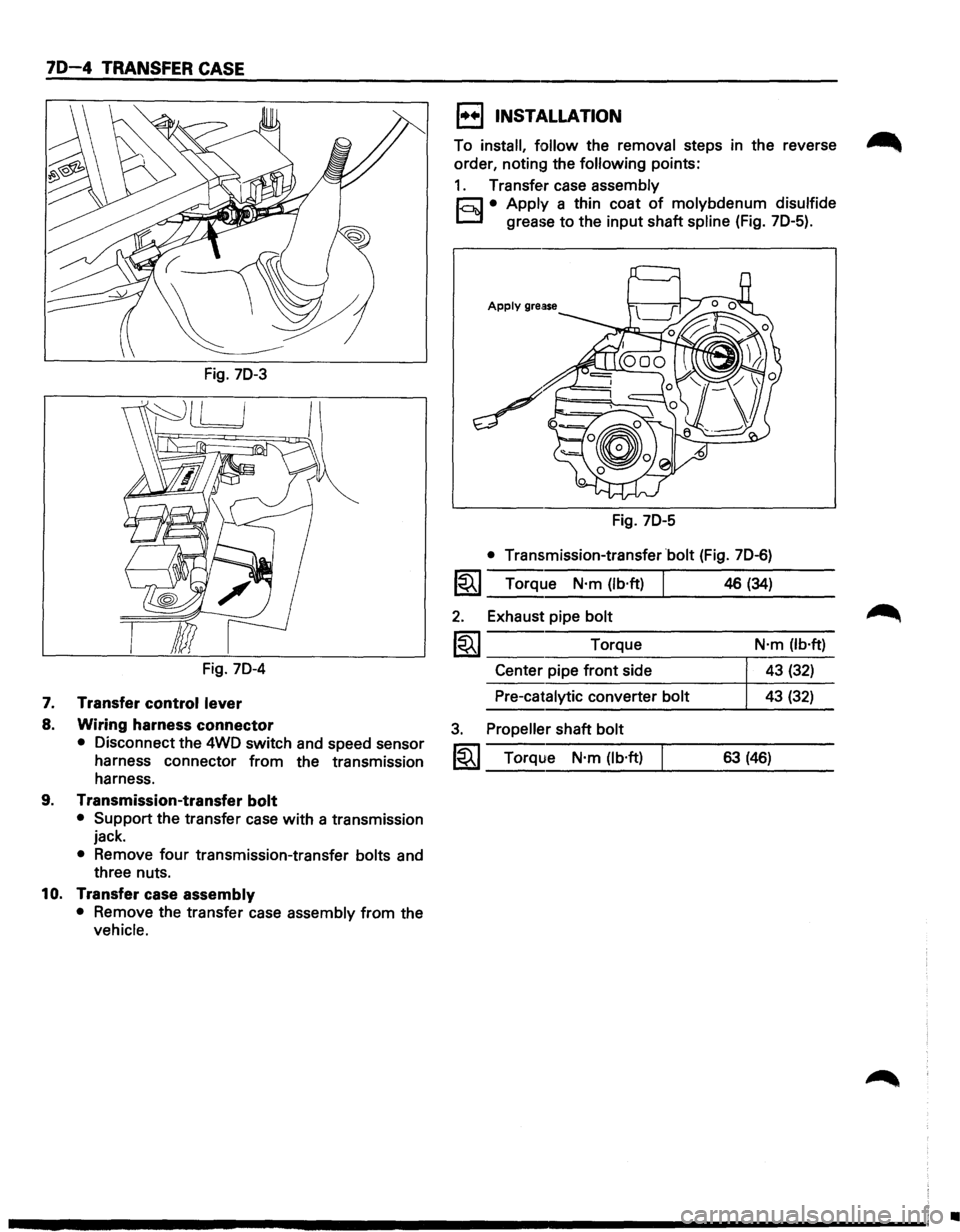
70-4 TRANSFER CASE
Fig. 70-3
Fig. 70-4
7. Transfer control lever
8. Wiring harness connector
• Disconnect the 4WD switch and speed sensor
harness connector from the transmission
harness.
9. Transmission-transfer bolt
• Support the transfer case with a transmission
jack.
• Remove four transmission-transfer bolts and
three nuts.
10. Transfer case assembly
• Remove the transfer case assembly from the
vehicle.
1••1 INSTALLATION
To install, follow the removal steps in the reverse ~
order, noting the following points:
1. Transfer case assembly
r;:;J • Apply a thin coat of molybdenum disulfide
D grease to the input shaft spline (Fig. 70-5).
Fig. 70-5
• Transmission-transfer bolt (Fig. 70-6)
1~1 Torque N·m (lb·ft)
2. Exhaust pipe bolt
1~1 Torque
Center pipe front side
Pre-catalytic converter bolt
3. Propeller shaft bolt
1~1 Torque N·m (lb·ft)
46 (34)
N·m (lb·ft)
43 (32)
43 (32)
63 (46)
•