sensor ISUZU TROOPER 1995 Workshop Manual
[x] Cancel search | Manufacturer: ISUZU, Model Year: 1995, Model line: TROOPER, Model: ISUZU TROOPER 1995Pages: 1928
Page 844 of 1928
6E2-148 DRIVEABILITY AND EMISSIONS
CHART C-5
KNOCK SENSOR (KS) SYSTEM CHECK
(ENGINE KNOCK, POOR PERFORMANCE, OR POOR ECONOMY)
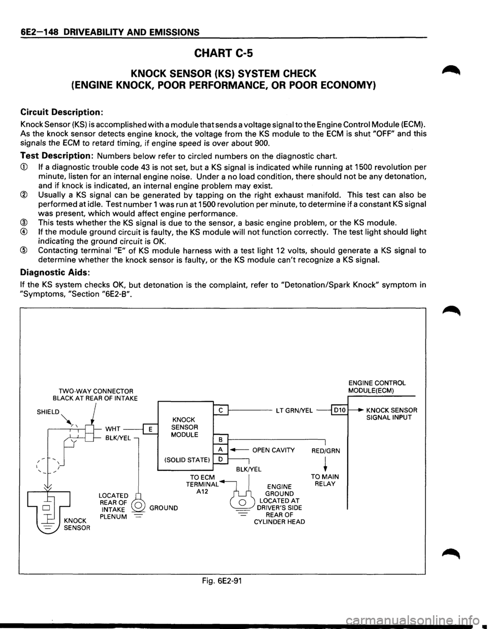
Circuit Description:
Knock Sensor (KS) is accomplished with a module that sends a voltage signal to the Engine Control Module {ECM).
As the knock sensor detects engine knock, the
voltage from the KS module to the ECM is shut "OFF" and this
signals the ECM to retard timing, if engine speed is over about 900.
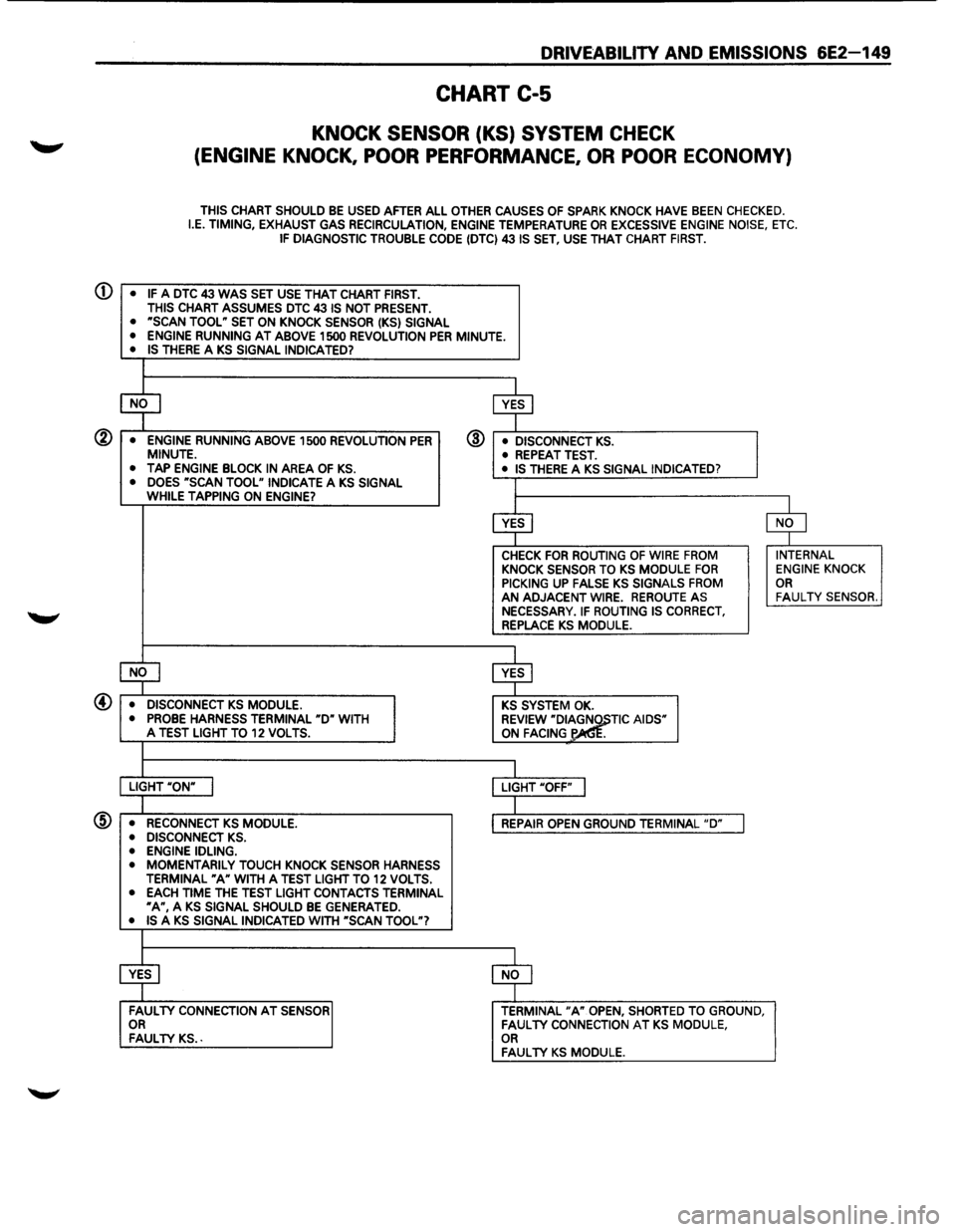
Test Description: Numbers below refer to circled numbers on the diagnostic chart.
CD If a diagnostic trouble code 43 is not set, but a KS signal is indicated while running at 1500 revolution per
minute,
listen for an internal engine noise. Under a no load condition, there should not be any detonation,
and
if knock is indicated, an internal engine problem may exist.
@ Usually a KS signal can be generated by tapping on the right exhaust manifold. This test can also be
performed at idle. Test number 1 was run at 1500 revolution per minute, to determine if a constant KS signal
was present, which would affect engine performance.
® This tests whether the KS signal is due to the sensor, a basic engine problem, or the KS module.
@ If the module ground circuit is faulty, the KS module will not function correctly. The test light should light
indicating the ground circuit is OK.
@ Contacting terminal "E" of KS module harness with a test light 12 volts, should generate a KS signal to
determine whether the knock sensor is faulty, or the KS module can't recognize a KS signal.
Diagnostic Aids:
If the KS system checks OK, but detonation is the complaint, refer to "Detonation/Spark Knock" symptom in
"Symptoms, "Section "6E2-8".
/ I
'
TWO-WAY CONNECTOR BLACK AT REAR OF INTAKE
I
-WHT
BLK!YEL
LOCATED REAR OF 0 INTAKE PLENUM
1------LT GRN/YEL
KNOCK
SENSOR
MODULE
BLK!YEL
GROUND
TOECM~ TERMINAL ENGINE A12 GROUND
0 LOCATEDAT _ DRIVER'S SIDE REAR OF CYLINDER HEAD
Fig. 6E2-91
RED/GRN
+ TO MAIN RELAY
ENGINE CONTROL
MODULE(ECM)
KNOCK SENSOR
SIGNAL INPUT
..
Page 845 of 1928
DRIVEABILITV AND EMISSIONS 6E2-149
CHART C-5
KNOCK SENSOR (KS) SYSTEM CHECK
(ENGINE KNOCK, POOR PERFORMANCE, OR POOR ECONOMY)
THIS CHART SHOULD BE USED AFTER ALL OTHER CAUSES OF SPARK KNOCK HAVE BEEN CHECKED. I.E. TIMING, EXHAUST GAS RECIRCULATION, ENGINE TEMPERATURE OR EXCESSIVE ENGINE NOISE, ETC. IF DIAGNOSTIC TROUBLE CODE (DTC) 431S SET, USE THAT CHART FIRST.
$ $
• ENGINE RUNNING ABOVE 1500 REVOLUTION PER @ • DISCONNECT KS. MINUTE. • REPEAT TEST. • TAP ENGINE BLOCK IN AREA OF KS. • IS THERE A KS SIGNAL INDICATED? • DOES ~scAN TOOL" INDICATE A KS SIGNAL I WHILE TAPPING ON ENGINE?
$ $
CHECK FOR ROUTING OF WIRE FROM INTERNAL KNOCK SENSOR TO KS MODULE FOR ENGINE KNOCK PICKING UP FALSE KS SIGNALS FROM OR AN ADJACENT WIRE. REROUTE AS FAUL TV SENSOR. NECESSARY. IF ROUTING IS CORRECT, REPLACE KS MODULE.
l4J $
• DISCONNECT KS MODULE. KS SYSTEM OK. • PROBE HARNESS TERMINAL "D" WITH REVIEW "DI~TIC AIDS" A TEST LIGHT TO 12 VOLTS. ON FACING .
I LIGHT "ON" I LIGHT "OFF" I
I • RECONNECT KS MODULE. REPAIR OPEN GROUND TERMINAL "D" J • DISCONNECT KS.
@
• ENGINE IDLING. • MOMENTARILY TOUCH KNOCK SENSOR HARNESS TERMINAL "A" WITH A TEST LIGHT TO 12 VOLTS. • EACH TIME THE TEST LIGHT CONTACTS TERMINAL ~A", A KS SIGNAL SHOULD BE GENERATED. • IS A KS SIGNAL INDICATED WITH "SCAN TOOL"?
$ $
FAULTY CONNECTION AT SENSOR TERMINAL "A" OPEN, SHORTED TO GROUND, OR FAULTY CONNECTION AT KS MODULE, FAULTY KS .. OR FAUL TV KS MODULE.
Page 850 of 1928
6E2-154 DRIVEABILITY AND EMISSIONS
CHART C-7A
EXHAUST GAS RECIRCULATION (EGR) SYSTEM CHECK
Circuit Description:
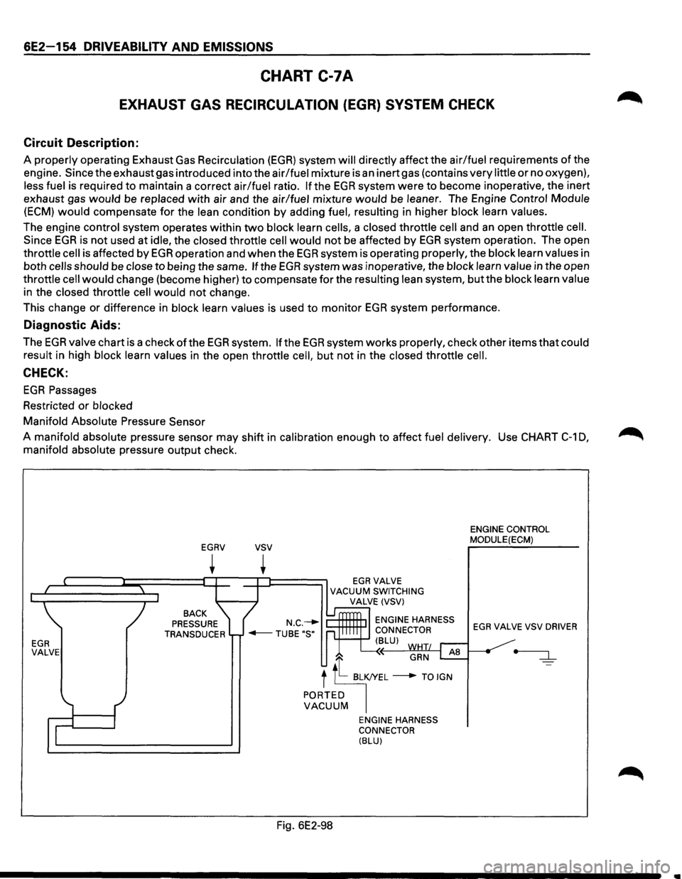
A properly operating Exhaust Gas Recirculation (EGR) system will directly affect the air/fuel requirements of the
engine. Since the exhaust gas introduced into the air/fuel mixture is
an inert gas (contains very little or no oxygen),
less fuel is required
to maintain a correct air/fuel ratio. If the EGR system were to become inoperative, the inert
exhaust gas
would be replaced with air and the air/fuel mixture would be leaner. The Engine Control Module
(ECM) would compensate for the lean condition by adding fuel, resulting in higher block learn values.
The engine control system operates within
two block learn cells, a closed throttle cell and an open throttle cell.
Since EGR is not used at idle, the closed throttle cell would not be affected by EGR system operation. The open
throttle
cell is affected by EGR operation and when the EGR system is operating properly, the block learn values in
both
cells should be close to being the same. If the EGR system was inoperative, the block learn value in the open
throttle
cell would change (become higher) to compensate for the resulting lean system, but the block learn value
in the closed throttle
cell would not change.
This change or difference in block learn values is used to monitor
EGR system performance.
Diagnostic Aids:
The EGR valve chart is a check of the EGR system. If the EGR system works properly, check other items that could
result in high block learn values in the open throttle
cell, but not in the closed throttle cell.
CHECK:
EGR Passages
Restricted
or blocked
Manifold Absolute Pressure Sensor
A manifold absolute pressure sensor may shift in calibration enough to affect fuel delivery. Use CHART
C-1 0,
manifold absolute pressure output check.
EGR VALVE
EGRV
+
BACK
PRESSURE
TRANSDUCER
vsv
+ EGRVALVE VACUUM SWITCHING
VALVE (VSV)
ENGINE HARNESS
CONNECTOR
'+--+-' ( BLU)
GRN AB
t tt BL~L ---+ TO IGN
PORTED VACUUM
Fig. 6E2-98
ENGINE HARNESS
CONNECTOR
(BLU)
ENGINE CONTROL
MODULE(ECM)
EGR VALVE VSV DRIVER
•
Page 853 of 1928
DRIVEABILITY AND EMISSIONS 6E2-157
SECTION C-8
SHIFT INDICATOR LIGHT (MIT ONLY)
CONTENTS
General Description . . . . . . . . . . . . . . . . . . . . . 6E2-157 Diagnosis ............................. 6E2-157
Purpose ............................ 6E2-157 Transmission Switch Functional Check ..... 6E2-157
Operation . . . . . . . . . . . . . . . . . . . . . . . . . . . 6E2-157 Clutch Switch Functional Check ........... 6E2-157
Chart C-8 Manual Transmission (M/T)
Shift Light ........................... 6E2-158
GENERAL DESCRIPTION
PURPOSE
The shift indicator light is a device which is installed in
the instrument
panel to urge the driver to up shiftatthe
proper moment. This insures operations for best fuel
economy.
OPERATION
It turns on as soon as vehicle conditions become
suitable for operation in the next higher gear, and turns
off as the clutch is released for up shift.
The engine parameters used
to activate the shift
indicator
light are engine speed, engine load and
engine
coolant temperature. The engine load is sensed
as a function of Throttle Body (TB) position by a sensor
built into the TB. The
shift indicator
light turns on when the following
conditions exist simultaneously:
1. Engine coolant temperature is hotter than -s·c.
2. TB is not in idle position.
3. The engine load, is not greater than the
predetermined
values.
4. The transmission gear is in any forward position
other then 5th, that is, either
of the two
transmission switches (1st-2nd switch and 3rd-
4th switch) is on. 1st-2nd switch turns on
when the
transmission is in 1st-2nd, and 3rd-4th switch
turns on when the transmission 3rd
or 4th.
5. The clutch is engaged (clutch switch is "ON").
The control system schematic is shown in CHART
C-8.
DIAGNOSIS
See CHART C-8.
TRANSMISSION SWITCH FUNCTIONAL
CHECK
1. Connector from the suspected faulty switch.
2. An ohmmeter across terminals of switch.
3. Operate gear shift.
4. Ohmmeter should indicate open (infinity) then
closed (00).
5. Replace switch if not operating as described.
CLUTCH SWITCH FUNCTIONAL CHECK
1. Remove clutch switch.
2. Ohmmeter to terminal of clutch switch.
3. Operate the clutch switch.
4. Ohmmeter should read "closed" (00) then
"open" (infinity) when clutch switch is pressed.
5. Replace switch if not operating as described.
Page 854 of 1928
6E2-158 DRIVEABILITV AND EMISSIONS
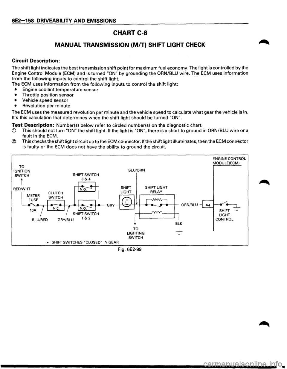
CHART C-8
MANUAL TRANSMISSION (M/T) SHIFT LIGHT CHECK
Circuit Description:
The shift light indicates the best transmission shift point for maximum fuel economy. The light is controlled by the
Engine Control Module
(ECM) and is turned "ON" by grounding the ORN/BLU wire. The ECM uses information
from the following inputs to control the shift light.
The
ECM uses information from the following inputs to control the shift light:
• Engine coolant temperature sensor
• Throttle position sensor
• Vehicle speed sensor
• Revolution per minute
The
ECM uses the measured revolution per minute and the vehicle speed to calculate what gear the vehicle is in.
It's this calculation that determines when the shift light should be turned "ON".
Test Description: Number(s) below refer to circled number(s) on the diagnostic chart.
ECM.
® This checks the shift light circuit up to the ECM connector .If the shift light illuminates, then the ECM connector
is faulty
or the ECM does not have the ability to ground the circuit.
TO
IGNITION SWITCH
t
BLU/RED GRY/BLU
•
SHIFT SWITCHES #CLOSED" IN GEAR
BLU/ORN
SHIFT SHIFT LIGHT
LIGHT
RELAY
TO
LIGHTING SWITCH
Fig. 6E2-99
ENGINE CONTROL
MODULE(ECMl
SHIFT
LIGHT
CONTROL
Page 866 of 1928
&F-4 ENGINE EXHAUST (V6 3.2L)
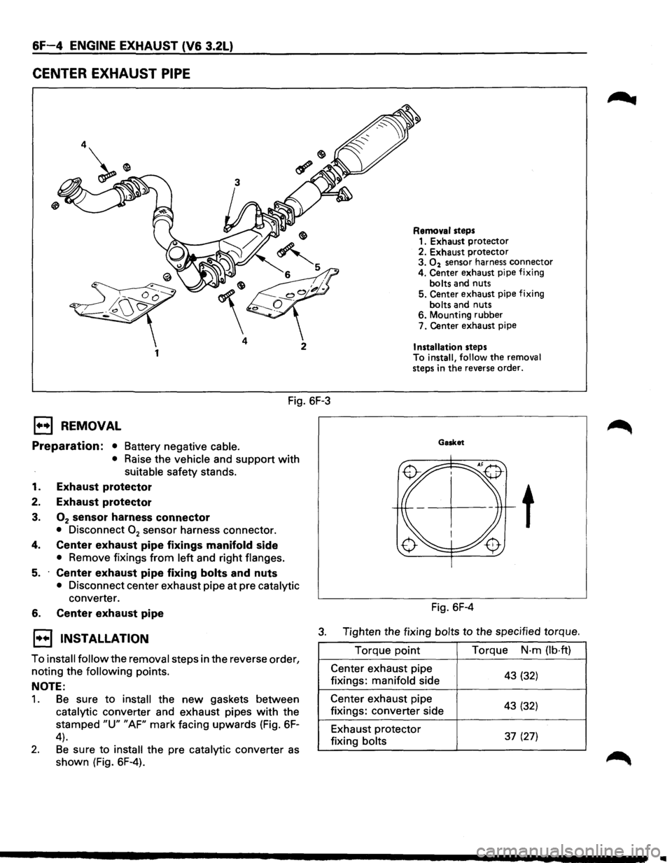
CENTER EXHAUST PIPE
4
1
Fig. 6F-3
E3 REMOVAL
Preparation: • Battery negative cable.
• Raise the vehicle and support with
suitable safety stands.
1. Exhaust protector
2. Exhaust protector
3. 02 sensor harness connector
• Disconnect 02 sensor harness connector.
4. Center exhaust pipe fixings manifold side
• Remove fixings from left and right flanges.
5. Center exhaust pipe fixing bolts and nuts
• Disconnect center exhaust pipe at pre catalytic
converter.
6. Center exhaust pipe
Removal steps 1. Exhaust protector
2. Exhaust protector
3.
02 sensor harness connector
4. Center exhaust pipe fixing
bolts and nuts
5. Center exhaust pipe fixing
bolts and nuts
6. Mounting rubber
7. Center exhaust pipe
Installation steps
To install, follow the removal
steps in the reverse order.
Gasket
t
Fig. 6F-4
1••1 INSTALLATION 3. Tighten the fixing bolts to the specified torque.
To
install follow the removal steps in the reverse order,
noting the
following points.
NOTE:
1. Be sure to install the new gaskets between
catalytic converter and exhaust pipes
with the
stamped
"U" "AF" mark facing upwards (Fig. 6F-
4).
2. Be sure to install the pre catalytic converter as
shown (Fig. 6F-4). Torque
point
Center exhaust pipe
fixings: manifold side
Center exhaust pipe
fixings: converter side
Exhaust protector
fixing bolts Torque
N·m
(lb·ft)
43 (32)
43 (32)
37 (27)
Page 874 of 1928
7A-2 AUTOMATIC TRANSMISSION (4L30-E)
Valve Body Assembly (Adapter Case) ....... 7A-168 Third Clutch and Sprag Unit ....................... 7A-195
Transmission Control
Module (TCM) ......... 7A-169 Third Clutch .................................................. 7A-196
Speed Sensor (Extension Housing) ............ 7A-169 Sprag
Unit ....................................................
7A-198
Transmission
Oil Temperature Sensor Second
Clutch .............................................. 7A-199
(Adapter Case) ..........................................
7A-170 3-4 Accumulator Piston ............................... 7A-200
Front Oil Seal (Converter Housing) ............ 7A-170 Reverse Clutch Piston and Center
Rear
Oil Seal (Extension Housing) ............. 7A-171 Support ..................................................... 7 A-202
Unit Repair ........................................................ 7A-173 Overrun Clutch and Turbine Shaft ............. 7A-204
Transmission (4L30-E) ................................. 7A-173 Main Data and Specifications ......................... 7 A-207
Converter Housing and Oil Pump General
Specifications ................................. 7 A-207
Assembly .................................................. 7 A-189 Torque
Specifications .................................. 7A-208
Oil
Pump ....................................................... 7A-190 Special Tools .................................................... 7A-211
Main Case Valve Body ................................. 7A-191 4L30-E Parts List.. ............................................. 7A-213
Adapter Case Valve Body ............................ 7A-193 Hydraulic
Circuit Diagram .......... End of This Manual
GENERAL DESCRIPTION
The 4L30-E is a 4-speed fully-automatic transmission.
It uses a microcomputer as a control unit to judge
running conditions
including throttle opening rate
and vehicle speed, then
it sets the shifting point in
the
optimum timing so that best driving performance
can be achieved.
In addition, the built-in shift mode select function can
select three shift modes according to the driver's
preference.
• Normal mode-Normal shift pattern.
• Winter mode-Starts in 3rd gear to reduce
slippage on ice
or snow.
• Power mode has a delayed upshift for when
more powerful acceleration is required.
Also, the built-in fail-safe
function ("backup mode")
assures driving performance even if the vehicle
speed sensor,
throttle signal or any solenoid fails.
Further, the self-diagnostic
function conducts diag
nosis in a short time when the control system fails,
thus improving serviceability.
The major features of 4L30-E are as follows:
• A compact structure consisting of 2 sets of
planetary gears and flat torque converter.
• Electronic control selects the optimum shift
mode according
to the driving conditions.
• Electronic control maintains the optimum hy
draulic pressure for clutch, band brake as well as
transmission so that shift feeling is improved.
• Two sets of planetary gears reduce friction of
power train.
Also, a lock-up mechanism in the torque con
verter reduces fuel consumption.
• Wide gear ratio and high torque rate of torque
converter provide
excellent starting perform
ance.
MODEL YEAR 1994-95 CHANGES
The Transmission Control Module (TCM) for ISUZU
TROOPER
models equipped with 4L30-E is changed
from "BOSCH" to "DELCO ELECTRONICS"
manufacture.
The main differences
which will be encountered
while servicing concerned vehicles are as follows:
Diagnostic Trouble Codes (DTC):
DTC's are changed: For example, DTC for
transmission gear error will be as follows depending
on the TCM unit:
-
On the "DELCO" unit (1994-95) ......... DTC 61
-On the "BOSCH" unit (1993-prior) ..... DTC 41
TCM Pin Connector:
The pin connector is changed. Therefore the
connections
to be made for troubleshooting also
change.
Shift Alteration when TECH 1 Tool is connected
toTCM:
SHIFTS WILL BE HARSH WHEN TECH 1 IS
CONNECTED.
Connection of TECH 1 automatically forces maximum
line pressure during shifts only.
Normal line pressure checks at idle and stall spe
can be carried out.
/
/
I J I
/
l
•
Page 876 of 1928
•
"'Tl c3' -..J )> I "'
~ )
DASH
BOARD
DISPLA
V
*
*
*
*
ATF
WARNING
LAMP
CHECK
TRANS
LAMP
POWER DRIVE MODE LAMP WINTER DRIVE MODE LAMP
~----------------
SHIFT INDICATOR
LAMP
COMPENSATION
FOR
ENGINE
LOAD
AIR CONDITIONING SWITCH
TI
DRIVER'S
INPUT
liJ
MANUAL
SELECTOR
~
KICK-DOWN SWITCH
" ~
BRAKE
SWITCH
*
(AfT
SHIFT INDICATOR)
CONTROL
UNIT
---
' ---
I-------------,
il
PUSH BUTTON
FOR
NORMALJPOWER
DRIVE MODE
ON-BOARD DIAGNOSTIC
j4
.. ,
..
l__l--1 L_-$-L_g
ENGINE CONTROL
MODULE
(ECM)
_ IGNITION
CONTROL
I
MODULE
i
THROTTLE POSITION
SENSOR
ENGINE SPEED SENSOR
l
I
I -
ENGINE COOLANT TEMPERATU~,_.TCH
)
I +12 IGNITION
• •
TRANSMISSION
CONTROL MODULE
(TCM)
j
L I
BATTERY
)
--
~
'
5SOLENOID VALVES
il
-·----·
___.
u
PUSH BUTTON
FOR
WINTER DRIVE MODE
OTHERS
OVERDRIVE
OFF
SIGNAL
(CRUISE CONTROLLER)
ABS
SIGNAL
(ABS CONTROLLER)
f.-
n_
VEHICLE SPEED
SENSOR
f-
/
ATF TEMPERATURE SENSOR
L__ L__
[PRNDJ2L
I MODE SWITCH
-
m
.....
r-
)>
m
I
(")
..;=...
-t
)>
;::g 0
c:
2
-1
-
0
(")
s:
(")
~
0
-
2
n
-t
-1
;::g
:a
0
)> z
r-
en
c
s:
:;
(i)
C)
en
~
0 z
3:
-..;=... r-w 0 I !!!
)
Page 877 of 1928
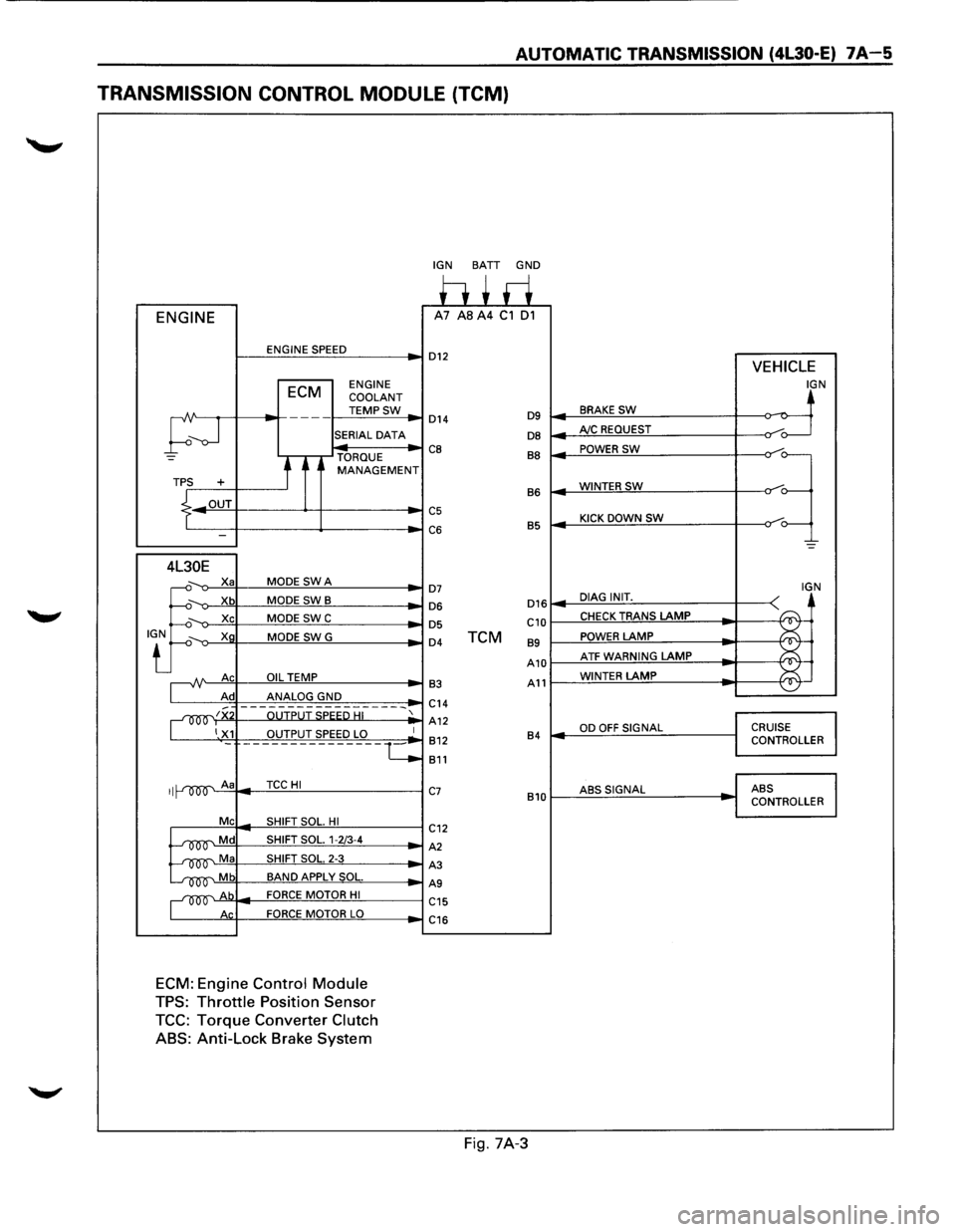
AUTOMATIC TRANSMISSION (4l30-E) 7A-5
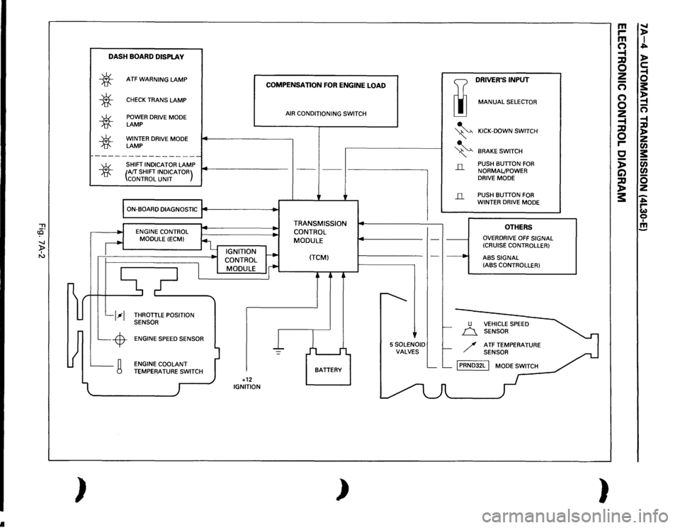
TRANSMISSION CONTROL MODULE (TCM)
ENGINE
ENGINE SPEED
ECM ENGINE
COOLANT
TEMPSW
;--J
---
SERIAL DATA
TORQUE
t MANAGEMENT TPS +
.L OUT
I -
4L30E
.J:
X a MODE SWA
Xb MODE SWB
Xc MODE SWC
Xg MODE SWG
A Ac OIL TEMP
Ad ANALOG GND
~~x OUTPUT SPEED HI
1 X1 OUTPUT SPEED LO
II A a TCCHI
Me SHIFT SOL. HI
~Md SHIFT SOL. 1-2/3-4
~Ma SHIFT SOL. 2-3
~Mb BAND APPLY SOL.
~Ab FORCE MOTOR HI
Ac FORCE MOTOR LO
ECM: Engine Control Module
TPS: Throttle Position Sensor
TCC: Torque Converter Clutch
ABS:
Anti-Lock Brake System
-
1
·-c
IGN BATT GND
h+ri A7 AS A4 C1 01
D12 VEHICLE
IGN
BRAKE SW ~ D14 D9 ~
DB AJC REQUEST /o---
CB BB POWER SW
=~
WINTERSW B6
C5 KICK DOWN SW C6 B5
-=
D7 IGN
D16 DIAG INIT. D6
~
D5 C10 CHECK TRANS LAMP
D4 TCM 89 POWER LAMP
A10 ATF WARNING LAMP ~
¥ 83 A11 WINTER LAMP
C14
A12
OD OFF SIGNAL CRUISE 812 84 CONTROLLER
811
C7 ABSSIGNAL ABS
810 CONTROLLER
C12
A2
A3
AS
C15
C16
Fig. 7A-3
Page 879 of 1928
1. SHIFT CONTROL
The transmission gear is shifted according to the
shift pattern selected by the driver.
~ In shifting gears, the gear ratio is controlled by the
ON/ OFF signal using the 1-2/3-4 shift solenoids and
the 2-3 shift solenoid.
2. BAND APPLY CONTROL
The band apply is controlled when in the 3-2
downshift (engine overrun prevention) and the
garage shift (shock control).
The band
apply solenoid is controlled by the signal
from the Pulse Width Modulation (PWM) to regulate
the
flow of the oil.
3. TORQUE CONVERTER CLUTCH CONTROL
The clutch ON/OFF is controlled by moving the
converter clutch valve through shifting Torque
Converter Clutch
(TCC) solenoid using the ON/OFF
signal.
4. LINE PRESSURE CONTROL
The throttle signal allows the current signal to be
sent
to the force motor. After receiving the current
signal, the force motor activates the pressure
regulator valve to regulate the line pressure.
5. ON-BOARD DIAGNOSTIC SYSTEM
Several malfunction displays can be stored in the
Transmission Control Module (TCM) memory, and
read
out of it afterward.
The serial data lines, which are required for the
testing of the final assembly and the coupling to
other electronic modules, can be regulated by this
function.
6 FAIL-SAFE MECHANISM
If there is a problem in the transmission system, the
TCM will go into a "backup" mode. The vehicle can
still be driven, but the driver must use the gear
lever to shift gears.
7. TORQUE MANAGEMENT CONTROL
The TCM sends the absolute spark advance signal
to the Engine Control Module (ECM) while the
transmission is being shifted, to control the engine
spark timing in compliance with the vehicle running
condition to reduce the shocks caused by the
change of speed.
8. ATF WARNING CONTROL
The oil temperature sensor detects the ATF oil
temperature to control the oil temperature warning,
TCC and the winter mode.
9. ABS CONTROL
When the select lever is at "L" or "R" range, a
signal is sent
to the ABS controller as one of the
ABS control conditions.
AUTOMATIC TRANSMISSION (4L30-E) 7A-7