torque ISUZU TROOPER 1995 Workshop Manual
[x] Cancel search | Manufacturer: ISUZU, Model Year: 1995, Model line: TROOPER, Model: ISUZU TROOPER 1995Pages: 1928
Page 643 of 1928
ENGINE FUEL 6C-1
SECTION 6C
ENGINE FUEL
CONTENTS
General Description ....................... .
Fuel Metering ............................ .
On-Vehicle Service ........................ .
Fuel Filter ................................. .
In Tank Fuel Filter ............................. .
Fuel Pump Flow Test ........................ .
Fuel Pump Assembly ........................ .
Fuel Pump Relay .............................. ..
6C-1
6C-2
6C-3
6C-3
6C-4
6C-4
6C-5
6C-5
Fuel Tank .......................................... ..
Fuel Gage Unit ................................. ..
Fuel Filler Cap .................................... .
Accelerator Pedal Control ............... ..
Accelerator Pedal Control Cable ..
Accelerator Pedal ......................... .
Air
Cleaner Filter ........................... .
Main Data and Specifications ............... .
Torque Specifications ......................
..
6C-6
6C-7
6C-7
6C-8
6C-8
6C-9
6C-10
6C-11
6C-11
GENERAL DESCRIPTION
When working on the fuel system, there are several
things to keep in mind:
• Any time the fuel system is being worked on,
disconnect the negative battery
cable except for
those tests where battery voltage is required.
• Always keep a dry chemical (Class 8) fire extin
guisher near the work area.
• Replace all pipes with the same pipe and fittings
that were removed.
• Clean and inspect "0" rings. Replace if required.
• Always relieve the line pressure before servicing
any fuel system components.
• Do not attempt repairs on the fuel system until you
have read the instructions and checked the pic
tures
relating to that repair.
• Adhere to all Notices and Cautions.
All gasoline engines are designed to use only unleaded
gasoline. Unleaded gasoline
must be used for proper
emission control system operation. Its use will also
minimize spark plug fouling and extend engine oil life.
Using leaded gasoline can damage the emission
control system and could result in loss of emission
warranty coverage.
All cars are equipped with an Evaporative Emission
Control System. The purpose of the system is to
minimize the escape offuel vapors to the atmosphere.
Information on this system will be found in Section
6E2.
Page 647 of 1928
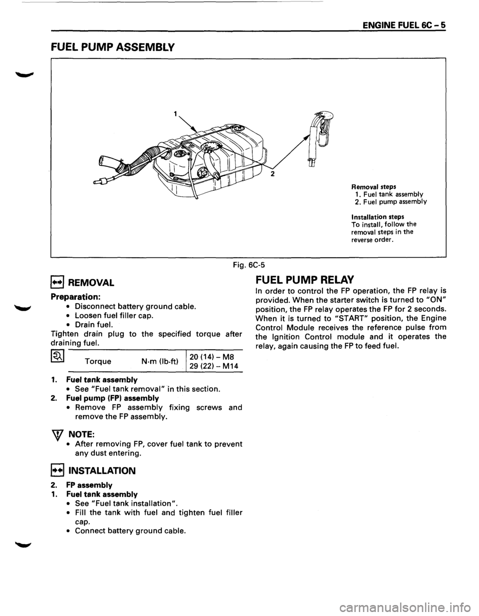
FUEL PUMP ASSEMBLY
1
ENGINE FUEL 6C-5
Removal steps
1. Fuel tank assembly 2. Fuel pump assembly
Installation
steps
To install, follow the removal steps in the reverse order.
Fig. 6C-5
B REMOVAL
Preparation:
• Disconnect battery ground cable.
•
Loosen fuel filler cap.
• Drain fuel.
Tighten drain plug to the specified torque after
draining fuel.
~ Torque N·m (lb.ft) 20 (14)-M8
29 (22)-M14
1. Fuel tank assembly
•
See "Fuel tank removal" in this section.
2. Fuel pump (FPI assembly
• Remove FP assembly fixing screws and
remove the FP assembly.
"'\f NOTE:
• After removing FP, cover fuel tank to prevent
any dust entering.
B INSTALLATION
2. FP assembly
1. Fuel tank assembly
• See "Fuel tank installation".
• Fill the tank with fuel and tighten fuel filler
cap.
• Connect battery ground cable.
FUEL PUMP RELAY
In order to control the FP operation, the FP relay is
provided. When the starter switch is turned to "ON"
position, the FP relay operates the FP for 2 seconds.
When it is turned to "START" position, the Engine
Control Module receives the reference pulse from
the Ignition Control module and it operates the
relay, again causing the FP to feed fuel.
Page 648 of 1928
6C-6 ENGINE FUEL
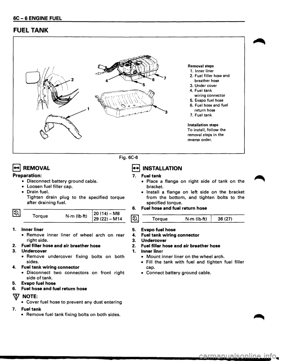
FUEL TANK
7
1 3
Removal steps
1.1nnerliner
2. Fuel filler hose and
breather hose
3. Under cover
4.
Fuel tank
wiring connector
5. Evapo fuel hose
6.
Fuel hose and fuel
return hose
7. Fuel tank
Installation steps
To
install, follow the
removal steps in the
reverse order.
Fig. 6C-6
B REMOVAL
Preparation:
• Disconnect battery ground cable.
•
Loosen fuel filler cap.
• Drain fuel.
Tighten drain plug to the specified torque
after draining fuel.
Torque
1. Inner liner
N·m (lb·ft) 20 (14)-M8
29 (22)-M14
• Remove
inner liner of wheel arch on rear
right side.
2.
Fuel filler hose and air breather hose
3.
Undercover
• Remove undercover fixing bolts on both
sides.
4. Fuel tank wiring connector
• Disconnect two connectors on front right
side of tank.
5. Evapo fuel hose
6. Fuel hose and fuel return hose
W NOTE:
• Cover fuel hose to prevent any dust entering
7. Fuel tank
• Remove fuel tank fixing bolts on both sides.
I!!] INSTALLATION
7.
6.
Fuel tank
• Place a flange on right side of tank on the
bracket.
• Install a flange on left side on the bracket
from the bottom, and tighten bolts to the
specified torque.
Fuel hose and fuel return hose
Torque N·m Ob·ft) 36 (27)
5. Evapo fuel hose
4. Fuel tank wiring connector
3. Undercover
2. Fuel filler hose and air breather hose
1. Inner liner
• Mount inner liner on the wheel arch.
• Fill the tank with fuel and tighten fuel filler
cap.
• Connect battery ground cable.
Page 649 of 1928
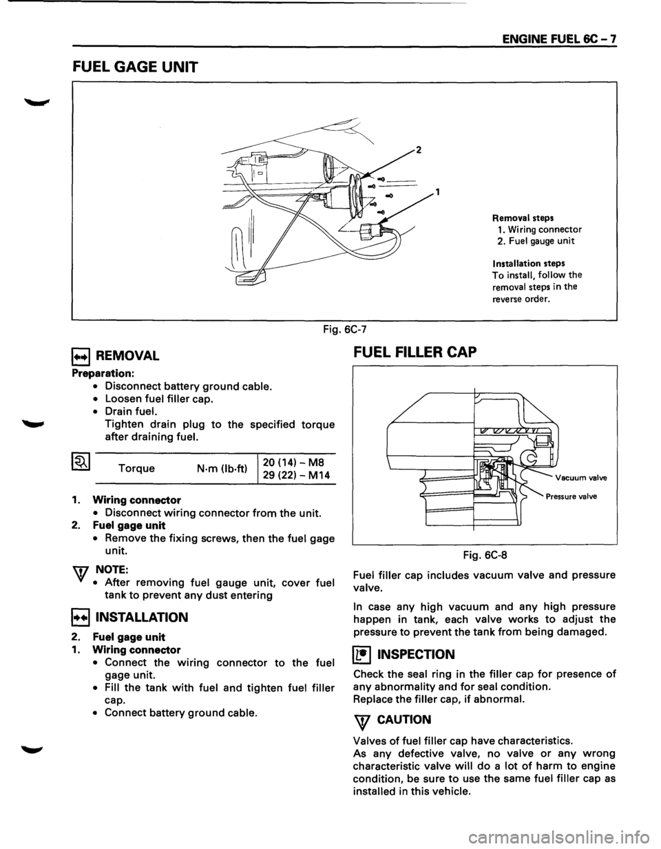
FUEL GAGE UNIT
1
ENGINE FUEL 6C - 7
Removal steps
1. Wiring connector
2. Fuel gauge unit
Installation steps
To
install, follow the
removal steps in the
reverse order.
Fig. 6C-7
E3REMOVAL ~F_U_E_L_F_IL_L_ER __ C_A_P ____________ ~
Preparation:
• Disconnect battery ground cable.
•
Loosen fuel filler cap.
• Drain fuel.
Tighten drain plug to the specified torque
after draining fuel.
Torque
1. Wiring connector
N-m (lb·ft) 20 (14)-M8
29 (22)-M14
• Disconnect wiring connector from the unit.
2. Fuel
gage unit
• Remove the fixing screws, then the fuel gage
unit.
w NOTE:
• After removing fuel gauge unit, cover fuel
tank to prevent any dust entering
B INSTALLATION
2. Fuel gage unit
1. Wiring connector
• Connect the wiring connector to the fuel
gage unit.
• Fill the tank with fuel and tighten fuel filler
cap.
• Connect battery ground cable.
Vacuum valve
Pressure valve
Fig. 6C-8
Fuel filler cap includes vacuum valve and pressure
valve.
In
case any high vacuum and any high pressure
happen in tank, each
valve works to adjust the
pressure to prevent the tank from being damaged.
(1!] INSPECTION
Check the seal ring in the filler cap for presence of
any abnormality and for seal condition.
Replace the filler cap, if abnormal.
\f CAUTION
Valves of fuel filler cap have characteristics.
As any defective valve, no valve or any wrong
characteristic valve will do a lot of harm to engine
condition, be sure to use the same fuel filler cap as
installed in this vehicle.
Page 653 of 1928
ENGINE FUEL 6C -11
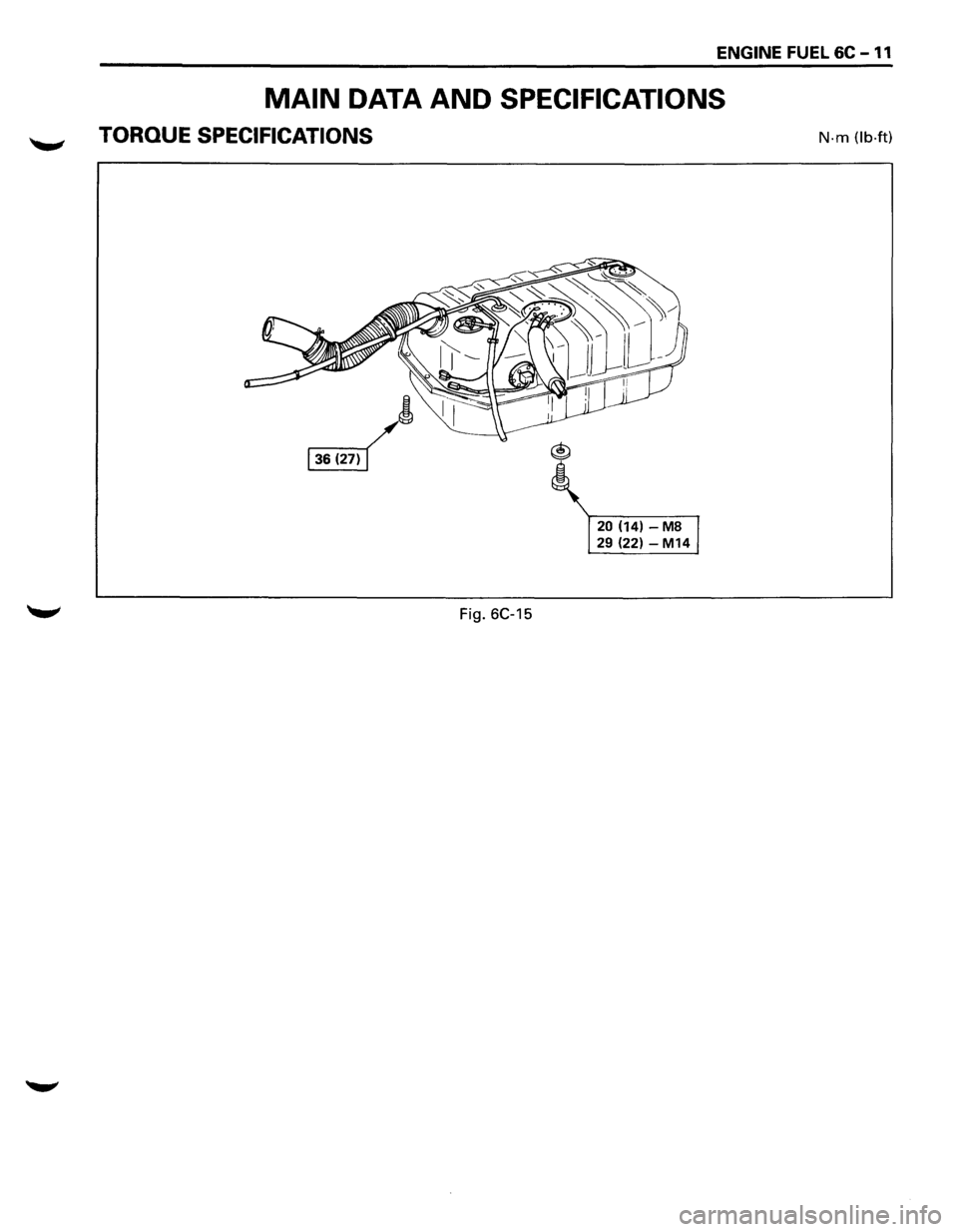
MAIN DATA AND SPECIFICATIONS
TORQUE SPECIFICATIONS
Fig. 6C-15
20 (14)-M8
29
(22)-M14
N·m (lb·ft)
Page 659 of 1928
CRANKING SYSTEM 6D2 - 1
SECTION 602
CRANKING SYSTEM
CONTENTS
General Description ....................... .
Diagnosis
.................................... .
On-Vehicle Service ........................ . 6D2-1
6D2-3
6D2-8 Unit
Repair.................................... 6D2-9
Main Data and Specifications
............ 6D2-17
Torque Specifications
...................... 6D2-18
GENERAL DESCRIPTION
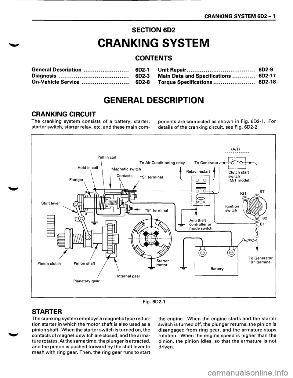
CRANKING CIRCUIT
The cranking system consists of a battery, starter,
starter switch, starter relay, etc. and these main com-
Pull in coil
Hold
in coil
Plunger
Shift lever
Pinion clutch
Internal
gear
Planetary gear
ponents are connected as shown in Fig. 602-1. For
details of the cranking circuit, see Fig. 602-2.
Anti theft controller or mode switch
Battery
(AfT} '-------------. ' '
To Generator "B" terminal
Fig. 602-1
STARTER
The cranking system employs a magnetic type reduc
tion starter in which the motor shaft is also used as a
pinion shaft. When the starter switch is turned on, the
contacts of magnetic switch are closed, and the arma
ture rotates. At the same time, the plunger is attracted,
and the pinion is pushed forward by the shift lever to
mesh with ring gear. Then, the ring gear runs to start
the engine. When the engine starts and the starter
switch is turned off, the plunger returns, the pinion is
disengaged from ring gear, and the armature stops
rotation. When the engine speed is higher than the
pinion, the pinion idles, so that the armature is not
driven.
Page 666 of 1928
602-8 CRANKING SYSTEM
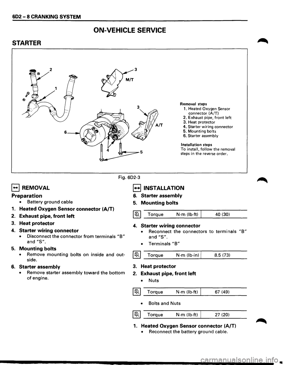
ON-VEHICLE SERVICE
STARTER
3
3
6
Removal steps
1. Heated
Oxygen Sensor connector (A/T)
2. Exhaust pipe, front left 3. Heat protector
4.
Starter wiring connector 5. Mounting bolts 6. Starter assembly
Installation
steps
To install, follow the removal steps in the reverse order.
Fig. 602-3
EJ REMOVAL
Preparation
• Battery ground cable
1. Heated Oxygen Sensor connector (A/T)
2. Exhaust pipe, front left
3. Heat protector
4. Starter wiring connector
• Disconnect the connector from terminals "B"
and "S".
B INSTALLATION
6. Starter assembly
5. Mounting bolts
~~~ Torque N·m (lb·ft) I
4. Starter wiring connector
40 (30)
• Reconnect the connectors to terminals "B"
and "S".
• Terminals "B"
5. Mounting bolts
• Remove mounting bolts on inside and out-~~~ Torque N·m (lb·in) I side. __ _;_ ______ -J.... ______ _ 8.5 (73)
6. Starter assembly
• Remove starter assembly toward the bottom
of engine.
3. Heat protector
2. Exhaust pipe, front left
• Nuts
~~~ Torque N·m (lb.ft)
• Bolts
and Nuts
~~~ Torque N·m (lb·ft) I
67 (49)
27
(20)
1. Heated Oxygen Sensor connector (A/T)
• Reconnect the battery ground cable.
..
Page 674 of 1928
602 -16 CRANKING SYSTEM
l•!•l REASSEMBL V
To install, follow the removal steps in the reverse
order,
noting the following points:
l<:::~ol Grease application places
• Bushing in rear cover and center bracket
• Gears in reduction gear
• Shift lever operating portion
• Sliding portion of pinion
• Plunger sliding portion of magnetic switch
Reassembling Yoke Assembly
Before reassembly, make sure that no metallic
parts attach to the yoke assembly. Because of
strong magnetic force, hold the yoke assembly
and insert it slowly into the armature.
@J TORQUE
Torque for each part (See page 602-18)
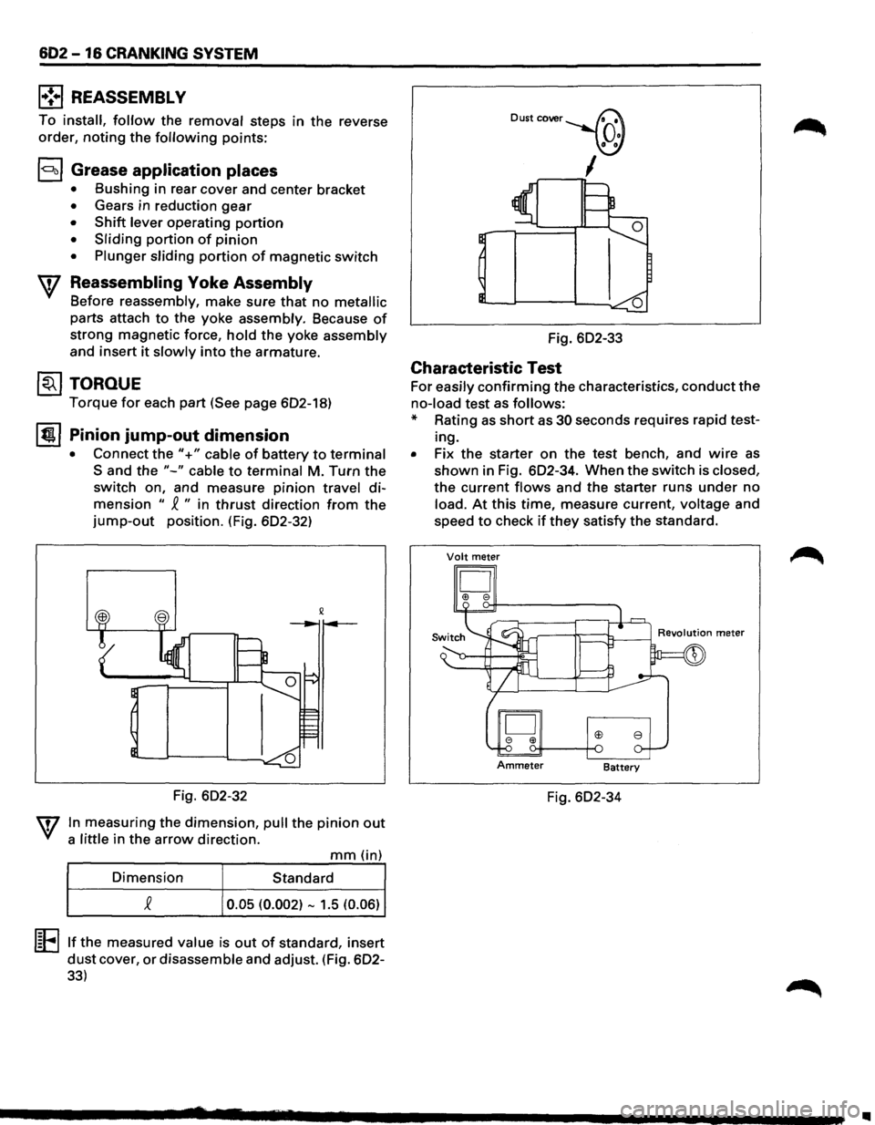
It!!!. I Pinion jump-out dimension
• Connect the"+" cable of battery to terminal
Sand the "-" cable to terminal M. Turn the
switch on, and measure pinion travel di
mension " ~ " in thrust direction from the
jump-out position. (Fig. 602-32)
Fig. 602-32
In measuring the dimension, pull the pinion out
a little in the arrow direction.
mm (in)
Dimension Standard
0.05 (0.002) -1.5 (0.06)
l~Ellf the measured value is out of standard, insert
dust cover, or disassemble and adjust. (Fig. 602-
33)
Dust cover~
_\(J)
,----,1
Fig. 602-33
Characteristic Test
For easily confirming the characteristics, conduct the
no-load test as follows:
* Rating as short as 30 seconds requires rapid test
ing.
• Fix the starter on the test bench, and wire as
shown in Fig. 602-34. When the switch is closed,
the current flows and the starter runs under no
load. At this time, measure current, voltage and
speed
to check if they satisfy the standard.
Volt meter
D I!> e
Fig. 602-34
..
Page 675 of 1928
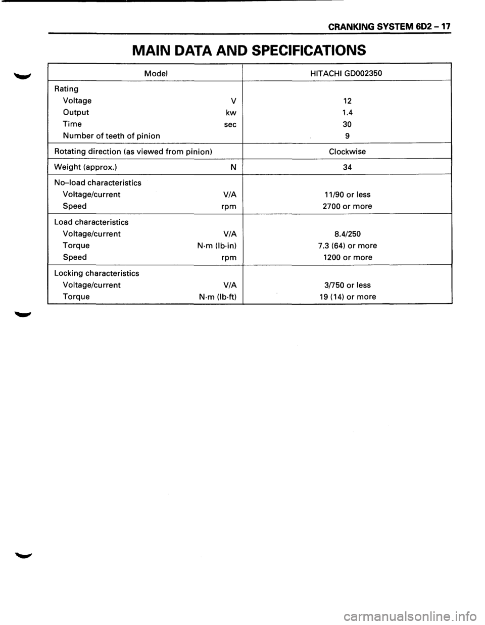
CRANKING SYSTEM 602-17
MAIN DATA AND SPECIFICATIONS
Model HITACHI GD002350
Rating
Voltage v 12
Output kw 1.4
Time sec 30
Number of teeth of pinion
9
Rotating direction (as viewed
from pinion) Clockwise
Weight (approx.)
N 34
No-load characteristics
Voltage/current V/A
11/90 or less
Speed rpm 2700 or more
Load characteristics
Voltage/current V/A
8.4/250
Torque N·m (lb·in) 7.3 (64) or more
Speed rpm 1200 or more
Locking characteristics
Voltage/current V/A
3/750 or less
Torque N·m (lb·ft) 19 (14) or more
Page 676 of 1928
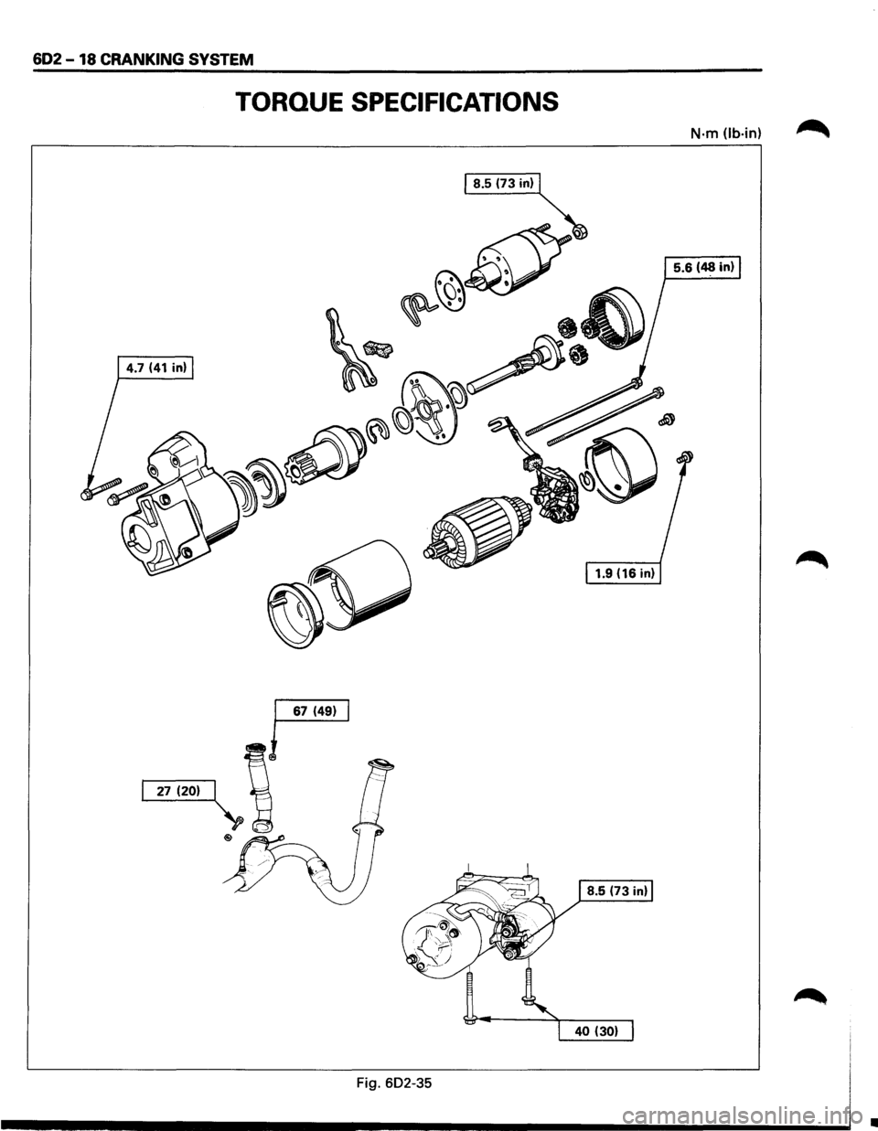
602-18 CRANKING SYSTEM
TORQUE SPECIFICATIONS
N·m (lb·in)
Fig. 602-35
•