torque ISUZU TROOPER 1995 Workshop Manual
[x] Cancel search | Manufacturer: ISUZU, Model Year: 1995, Model line: TROOPER, Model: ISUZU TROOPER 1995Pages: 1928
Page 606 of 1928
~:· T·, ·.}:
6A1-48 ENGINE (V6 3.2L DOHC AND SOHC)
33. Cylinder head cover
• Remove 11 fixing bolts, then the cylinder head
cover.
34. Power steering pump bracket
• Disconnect ground cable from bracket.
35.
• Remove five fixing bolts, then the bracket.
Exhaust front pipe
36.
37. Level gage fixing bolt
• Remove from cylinder head.
Cylinder head
1••1 INSTALLATION
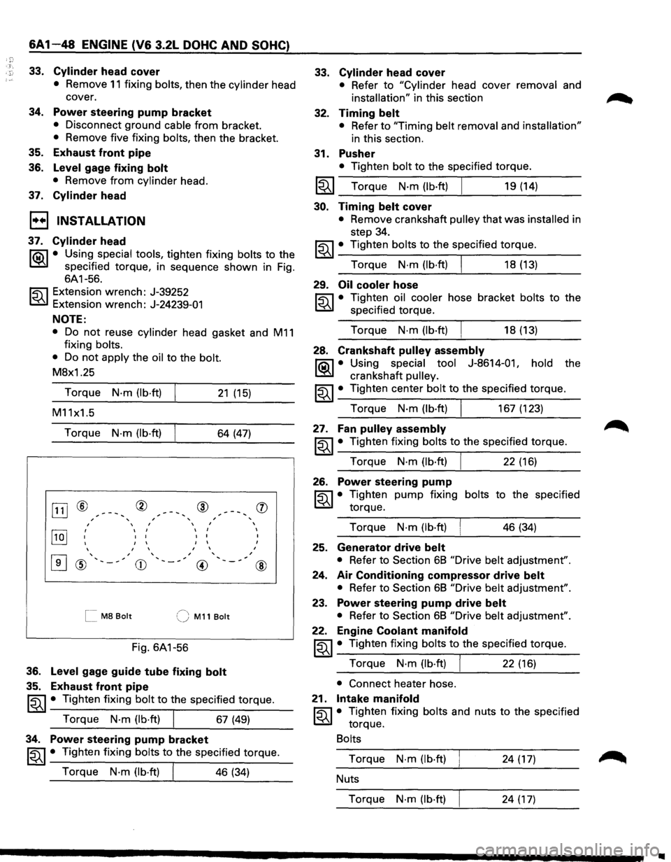
37. Cylinder head
li0\1 • Using special tools, tighten fixing bolts to the
~ specified torque, in sequence shown in Fig.
6A1-56.
~ Extension wrench: J-39252
t:6.l Extension wrench: J-24239-01
NOTE:
• Do not reuse cylinder head gasket and M11
fixing bolts.
•
Do not apply the oil to the bolt.
M8x1.25
Torque
N·m (lb·ft) 21 (15)
M11x1.5
Torque
N·m (lb·ft) 64 (47)
OJ] ® ® ® , ' ' ,
, I , ,
[IQJ ' I I
I I
I I I
I I
I I I
I I
,
[I] ' , , ' @ ' ,
CD ' , , __
@
[[ M8 Bolt (J M11 Bolt
Fig.
6A1-56
36. Level gage guide tube fixing bolt
35. Exhaust front pipe
'
,
(])
I
I
I
,
@
~~~ • Tighten fixing bolt to the specified torque.
Torque
N·m (lb·ft) I 67 (49)
34. Power steering pump bracket
~~~ • Tighten fixing bolts to the specified torque.
Torque
N·m (lb·ft) I 46 (34)
33.
32.
31.
Cylinder head cover
• Refer to "Cylinder head cover removal and
installation" in this section
Timing belt
• Refer to "Timing belt removal and installation"
in this section.
Pusher
• Tighten bolt to the specified torque.
I~I __ T_o_r~qu_e __ N_·_m~(lb_·ft_)~ ______ 1_9_(1_4_) ____ _
30. Timing belt cover
• Remove crankshaft pulley that was installed in
step 34.
~~~· Tighten bolts to the specified torque.
Torque
N·m (lb·ft) I 18 (13)
29. Oil cooler hose
~ • Tighten oil cooler hose bracket bolts to the
t:6.l specified torque.
Torque
N·m (lb·ft) I 18 (13)
28. Crankshaft pulley assembly
li0\1 • Using special tool J-8614-011 hold the
~ crankshaft pulley.
~~~ • Tighten center bolt to the specified torque.
Torque
N·m (lb·ft) I 167 (123)
27. Fan pulley assembly
~~~· Tighten fixing bolts to the specified torque.
Torque
N·m (lb·ft) I 22 (16)
26. Power steering pump
~ • Tighten pump fixing bolts to the specified
t:6.l torque.
Torque
N·m (lb·ft) I 46 (34)
25. Generator drive belt
• Refer to Section 68 "Drive belt adjustment".
24.
Air Conditioning compressor drive belt
• Refer to Section 68 "Drive belt adjustment".
23. Power steering pump drive belt
• Refer to Section 68 "Drive belt adjustment".
22. Engine Coolant manifold
~~~· Tighten fixing bolts to the specified torque.
Torque
N·m (lb·ft) I 22 (16)
• Connect heater hose.
21.
Intake manifold
~ • Tighten fixing bolts and nuts to the specified
t:6.l torque.
Bolts
Torque N·m (lb·ft) 24 (17)
Nuts
Torque
N·m (lb·ft) 24 (17)
..
Page 607 of 1928
20. Fuel injector connectors
• Connect to each injector.
19. Fuel hoses
• Connect the hoses securely and install the bolts
on the head cover.
18. Common chamber
• Tighten bolts and nuts to the specified torque.
Bolts
Torque N·m (lb·ft) 24 (17)
Nuts
Torque
N·m (lb·ft) 24 (17)
17. Throttle body
• Connect the engine coolant hose.
16. Common chamber duct
~~~ • Tighten bolts and nuts to the specified torque.
Bolts
Torque N-m (lb·ft) 24 (17)
Nuts
Torque
N·m (lb·ft) 24 (17)
• Connect the ground cable.
15. Exhaust Gas Recirculation Valve assembly
• Tighten bolts to the specified torque.
Exhaust Gas Recirculation
Valve Side
~~~ Torque N·m (lb·in) I 8 (69)
Exhaust Manifold Side
~~~ Torque N·m (lb·ft) 28 (21)
14. Canister vacuum hose
13.
Fuel Pressure Control Valve vacuum hose
12. Positive
Crankcase Ventilation hose
10. Throttle body
~~~· Tighten bolts to the specified torque.
Torque
N·m (lb·ft) I 19 (14)
11. Vacuum hoses
• Connect vacuum hoses on canister Vacuum
Switching Valve and Exhaust Gas Recirculation
Vacuum Switching Valve to the throttle body.
9. Ignition Control Module assembly
~~~· Tighten bolts to the specified torque and
connect connector.
Torque
N-m (lb·ft) 19 (14)
8. High tension cables
7. Connectors
• Connect each connector without fail.
~· 6. Vacuum booster hose
ENGINE (V6 3.2L DOHC AND SOHC) 6A 1-49
5. Canister vacuum hose
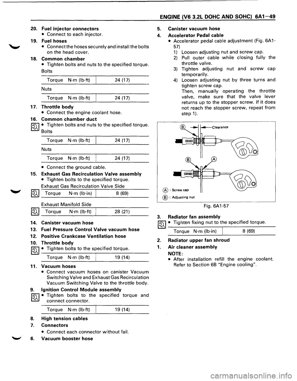
4. Accelerator Pedal
cable
• Accelerator pedal cable adjustment (Fig. 6A 1-
57)
1) Loosen adjusting nut and screw cap.
2) Pull outer cable while closing fully the
throttle valve.
3) Tighten adjusting nut and screw cap
temporarily.
4) Loosen adjusting nut by three turns and
tighten
screw cap.
Then,
manually operating the throttle
valve,
make sure that the valve lever
returns up to the stopper screw. If it does
not reach the stopper screw, repeat from
step 1 ).
@:Screw cap
@ : Adjusting nut
Fig. 6A1-57
3. Radiator fan assembly
~~~· Tighten fixing nut to the specified torque.
Torque
N-m (lb·in) I 8 (69)
2. Radiator upper fan shroud
1. Air cleaner assembly
NOTE:
• After installation refill the engine coolant.
Refer to Section 6B "Engine cooling".
Page 609 of 1928
.., ¢'
-
Fig. 6A1-59
1••1 INSTALLATION
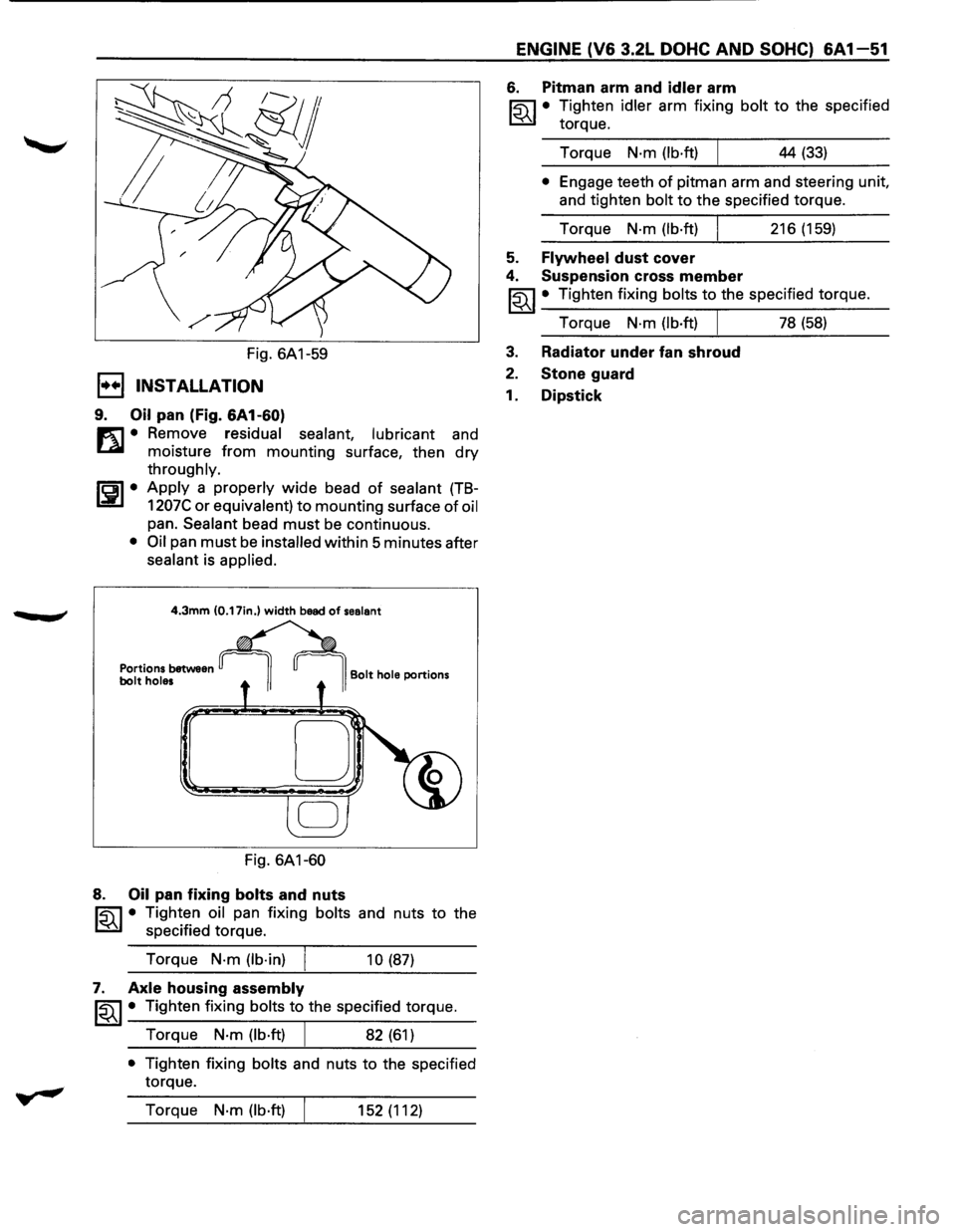
9. Oil pan (Fig. 6A1-60)
m • Remove residual sealant, lubricant and
~ moisture from mounting surface, then dry
throughly.
ISPI• Apply a properly wide bead of sealant (TB-
1207C or equivalent) to mounting surface of oil
pan. Sealant bead must be continuous.
• Oil pan must be installed within 5 minutes after
sealant is applied.
4.3mm (0.17in.) width bead of sealant
Portions between bolt holes
Fig. 6A1-60
8. Oil pan fixing bolts and nuts
Bolt hole portions
~ • Tighten oil pan fixing bolts and nuts to the
~ specified torque.
Torque
N·m (lb·in)
10 (87)
7. Axle housing assembly
~~~· Tighten fixing bolts to the specified torque.
Torque
N·m (lb·ft) 82 (61)
• Tighten fixing bolts and nuts to the specified
torque.
Torque
N·m (lb·ft) 152 (112)
ENGINE (V6 3.2L DOHC AND SOHC) 6A 1-51
6. Pitman arm and idler arm
~·
Tighten idler arm fixing bolt to the specified
torque.
Torque
N·m (lb·ft) 44 (33)
• Engage teeth of pitman arm and steering unit,
and tighten
bolt to the specified torque.
Torque
N·m (lb·ft) 216 (159)
5. Flywheel dust cover
4. Suspension cross member
~~~ • Tighten fixing bolts to the specified torque.
Torque
N·m (lb·ft) I 78 (58)
3. Radiator under fan shroud
2. Stone guard
1. Dipstick
Page 611 of 1928
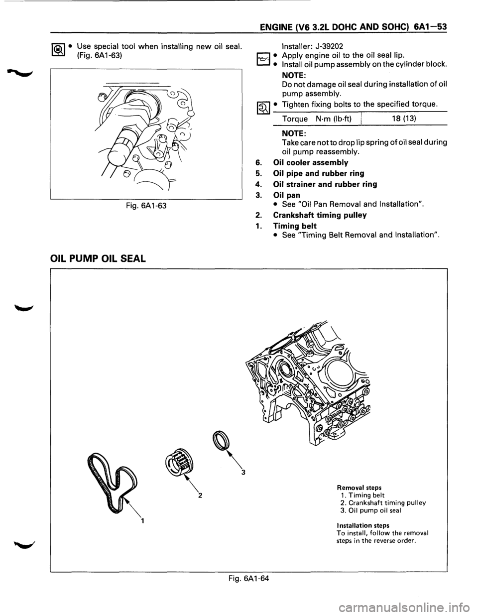
1®.1• Use special tool when installing new oil seal.
(Fig. 6A 1-63)
Fig. 6A1-63
OIL PUMP OIL SEAL
'
3
ENGINE (V6 3.2L DOHC AND SOHC) 6A 1-53
l'l::r.l :
Installer: J-39202
Apply
engine oil to the oil seal lip.
Install oil
pump assembly on the cylinder block.
NOTE:
Do not damage oil seal during installation of oil
pump assembly.
~~~· Tighten fixing bolts to the specified torque.
Torque
N·m (lb·ft) 18 (13)
NOTE:
Take care notto drop lip spring of oil seal during
oil pump reassembly.
6. Oil cooler assembly
5. Oil pipe and rubber ring
4.
Oil strainer and rubber ring
3. Oil pan
• See "Oil Pan Removal and Installation".
2. Crankshaft timing pulley
1. Timing belt
• See "Timing Belt Removal and Installation".
Removal steps 1. Timing belt 2. Crankshaft timing pulley 3. Oil pump oil seal
Installation steps To install, follow the removal steps in the reverse order.
Fig. 6A1-64
Page 613 of 1928
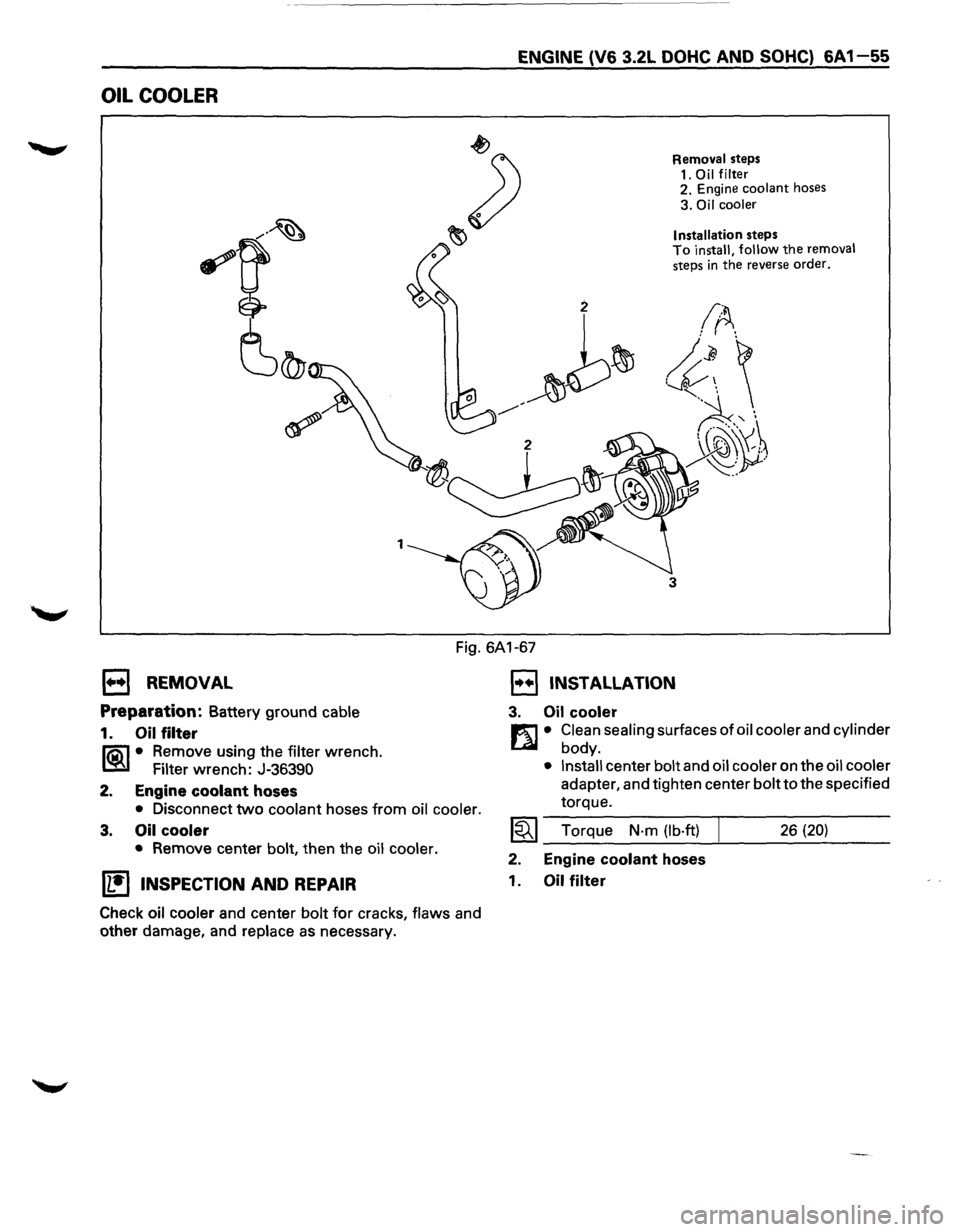
OIL COOLER
1
ENGINE (V6 3.2L DOHC AND SOHC) 6A 1-55
Removal steps
1.
Oil filter 2. Engine coolant hoses
3. Oil cooler
Installation
steps To install, follow the removal steps in the reverse order.
3
Fig. 6A1-67
1••1 REMOVAL
Preparation: Battery ground cable
1. Oil filter
li5\1 • Remove using the filter wrench.
~ Filter wrench: J-36390
2. Engine
coolant hoses
• Disconnect two coolant hoses from oil cooler.
3. Oil cooler
• Remove center bolt, then the oil cooler.
U!)INSPECTION AND REPAIR
Check oil cooler and center bolt for cracks, flaws and
other damage, and
replace as necessary.
1••1 INSTALLATION
3. Oil cooler
m • Clean sealing surfaces of oil cooler and cylinder
L41 body.
• Install center bolt and oil cooler on the oil cooler
adapter, and tighten center bolt to the specified
torque.
~~~ Torque N·m (lb·ft) 26 (20)
2. Engine coolant hoses
1.
Oil filter
Page 614 of 1928
 ~-;_' ;_\
~: PISTON, PISTON RINGS AND CONNECTING ROD
5
6
2
Removal steps 1. Cylinder head
2. Oil pan
3. Oil pipe and rubber ring
4. Oil strainer an")
6A 1-56 ENGINE (V6 3.2L DOHC AND SOHC) ~-;_' ;_\'
~: PISTON, PISTON RINGS AND CONNECTING ROD
5
6
2
Removal steps 1. Cylinder head
2. Oil pan
3. Oil pipe and rubber ring
4. Oil strainer and rubber ring
5.
Oil gallery
6. Piston
and connecting rod assembly
Installation steps
To install, follow the removal
steps in the reverse order.
Fig. 6A1-68
1••1 REMOVAL
1. Cylinder head
• See "Cylinder Head Removal and Installation".
2. Oil pan
• See "Oil Pan Removal and Installation".
3. Oil pipe and rubber ring
4. Oil strainer and rubber ring
5.
Oil gallery
6. Piston and connecting rod assembly
• Before removing the bearing cap, remove
carbon on the top
of cylinder bore.
• Push piston and connecting rod out from the
top of cylinder bore.
1••1 INSTALLATION
6. Piston and connecting rod assembly
19:::7;1• Apply engine oil to cylinder bore, connecting
rod bearings and crank pins.
• When installing the piston, its front mark must
face the engine front side. (Fig. 6A 1-69)
• The bearing cap number must be same as
connecting rod number.
1~1 • Apply engine oil to the thread and sealing
surface
of each nut.
~~~· Tighten nuts to the specified torque.
Torque
N·m (lb·ft) 54 (40)
NOTE:
• Do not apply engine oil to the bearing back
faces and connecting rod bearing fitting
surfaces.
•
Page 616 of 1928
,): .. • T·
6A 1-58 ENGINE (V6 3.2L DOHC AND SOHC)
EJ REMOVAL
1. Engine assembly
• See "Engine Assembly
Removal and Instal-
lation".
2. Crankshaft pulley
3. Timing belt cover
4. Timing belt
5. Oil pan
6. Oil pipe and rubber ring
7. Oil strainer and rubber ring
8. Oil pump assembly
9. Crankcase side bolts
10.
Oil gallery
11. Flywheel
12.
Rear oil seal retainers
13.
Connecting rod caps
14.
Crankshaft main bearing caps
15.
Crankshaft and main bearings
1•+1 INSTALLATION
15. Crankshaft and main bearings
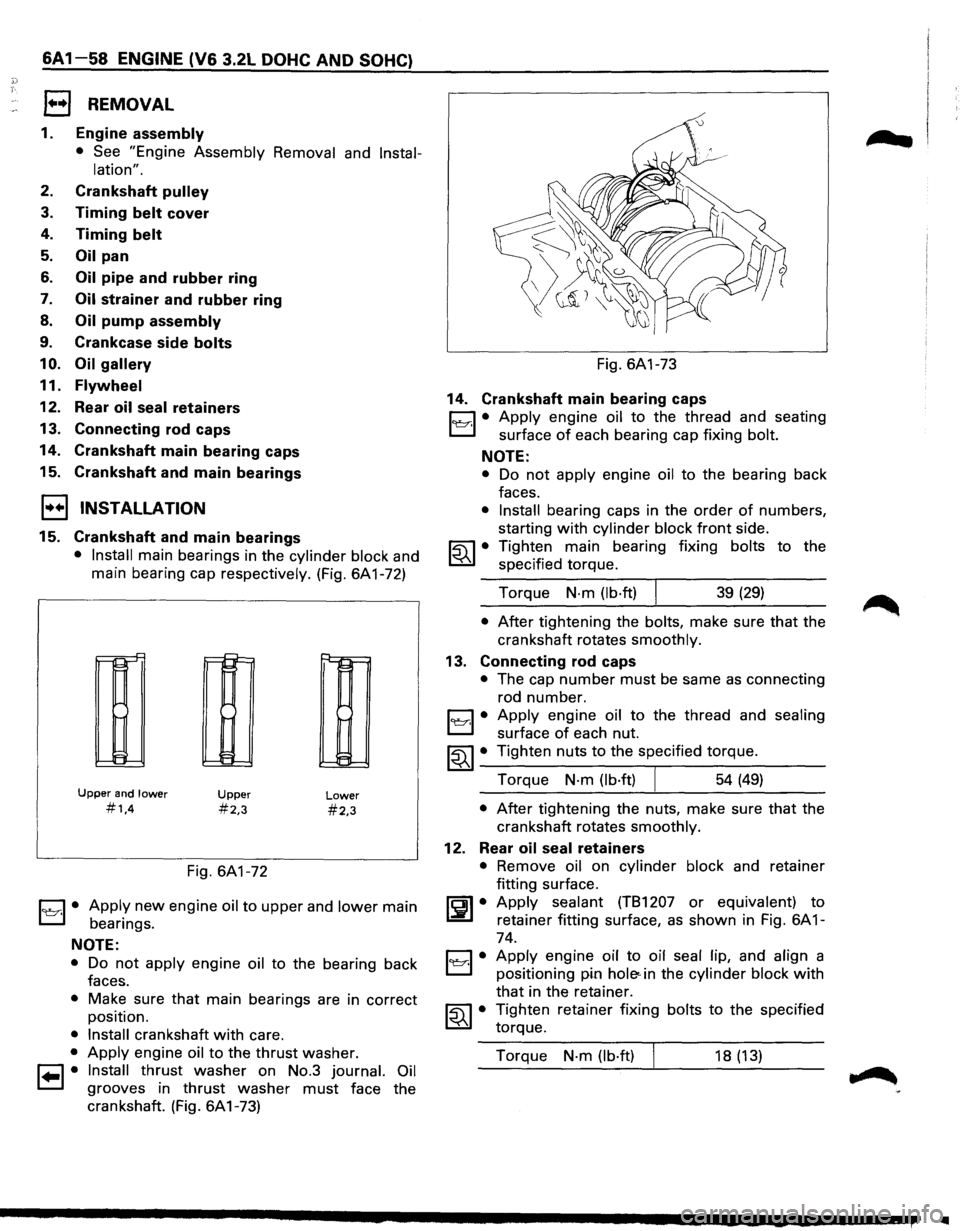
• Install main bearings in the cylinder block and
main bearing cap respectively. (Fig. 6A1-72)
r-r-'
II-
!:=
Upper and lower
#1,4
~
!::
E:
Upper
#2,3
Fig. 6A1-72
Lower
#2,3
1~1· Apply new engine oil to upper and lower main
bearings.
NOTE:
• Do not apply engine oil to the bearing back
faces.
• Make sure that main bearings are in correct
position.
• Install crankshaft with care.
• Apply engine oil to the thrust washer.
1•1• Install thrust washer on No.3 journal. Oil
grooves in thrust washer must face the
crankshaft. (Fig. 6A1-73) Fig.
6A1-73
14. Crankshaft main bearing caps
C1 • Apply engine oil to the thread and seating
L:::J surface of each bearing cap fixing bolt.
NOTE:
• Do not apply engine oil to the bearing back
faces.
• Install bearing caps in the order of numbers,
starting
with cylinder block front side.
~~~ • Tighten main bearing fixing bolts to the
specified torque.
Torque
N·m (lb·ft) I 39 (29)
• After tightening the bolts, make sure that the
crankshaft rotates
smoothly.
13. Connecting rod caps
• The cap number must be same as connecting
rod number.
1~1· Apply engine oil to the thread and sealing
surface of each nut.
~~~· Tighten nuts to the specified torque.
Torque
N·m (lb·ft) 54 (49)
• After tightening the nuts, make sure that the
crankshaft rotates
smoothly.
12. Rear oil seal retainers
• Remove oil on cylinder block and retainer
fitting surface.
~~~· Apply sealant (TB1207 or equivalent) to
retainer fitting surface, as shown in Fig. 6A 1-
74.
C1 • Apply engine oil to oil seal lip, and align a
El positioning pin hole< in the cylinder block with
that in the retainer.
~~~· Tighten retainer fixing bolts to the specified
torque.
Torque
N·m (lb·ft) 18 (13)
IIIII
Page 617 of 1928
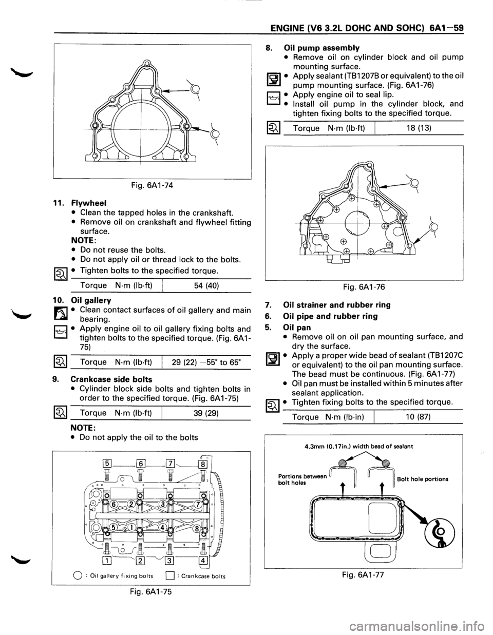
Fig. 6A1-74
11. Flywheel
• Clean the tapped holes in the crankshaft.
• Remove oil on crankshaft and flywheel fitting
surface.
NOTE:
• Do not reuse the bolts.
•
Do not apply oil or thread lock to the bolts.
~~~ • Tighten bolts to the specified torque.
Torque
N-m (lb·ft) 54 (40)
10. Oil gallery
m • Clean contact surfaces of oil gallery and main
~ bearing.
D • Apply engine oil to oil gallery fixing bolts and
L:::J tighten bolts to the specified torque. (Fig. 6A 1-
75)
~~~ Torque N·m (lb·ft) 29 (22) -55° to 65°
9. Crankcase side bolts
• Cylinder block side bolts and tighten bolts in
order
to the specified torque. (Fig. 6A 1-75)
~~~ Torque N·m (lb·ft) 39 (29)
NOTE:
• Do not apply the oil to the bolts
0 :Oil gallery fixing bolts 0: Crankcase bolts
Fig. 6A1-75
ENGINE (V6 3.2L DOHC AND SOHC) 6A1-59
8. Oil pump assembly
• Remove oil on cylinder block and oil pump
mounting surface.
ll:JI• Apply sealant (TB12078 or equivalent) to the oil
pump mounting surface. (Fig. 6A1-76)
19Y·I •. Apply engine oil to seal lip.
Install oil
pump in the cylinder block, and
tighten fixing
bolts to the specified torque.
1~1 Torque N·m (lb·ft)
Fig. 6A1-76
7. Oil strainer and rubber ring
6. Oil pipe and rubber ring
5. Oil pan
18 (13)
• Remove oil on oil pan mounting surface, and
dry the surface.
~~~· Apply a proper wide bead of sealant (TB1207C
or equivalent) to the oil pan mounting surface.
The bead
must be continuous. (Fig. 6A1-77)
• Oil pan must be installed within 5 minutes after
sealant application.
~~~· Tighten fixing bolts to the specified torque.
Torque
N·m (lb·in) 10 (87)
4.3mm (0.17in.) width bead of sealant
Portions between bolt holes I Bolt hole portions
D
Fig. 6A1-77
Page 618 of 1928
6A1-60 ENGINE (V6 3.2L DOHC AND SOHC}
4. Timing belt
• See "Timing Belt Removal and Installation".
3. Timing belt cover
2. Crankshaft pulley
~ • Using special tool J-8614-01, hold the
~ crankshaft pulley.
~~~· Tighten center bolt to the specified torque.
Torque
N·m (lb·ft) 167 (123)
1. Engine assembly
• See "Engine Assembly Removal and Instal
lation".
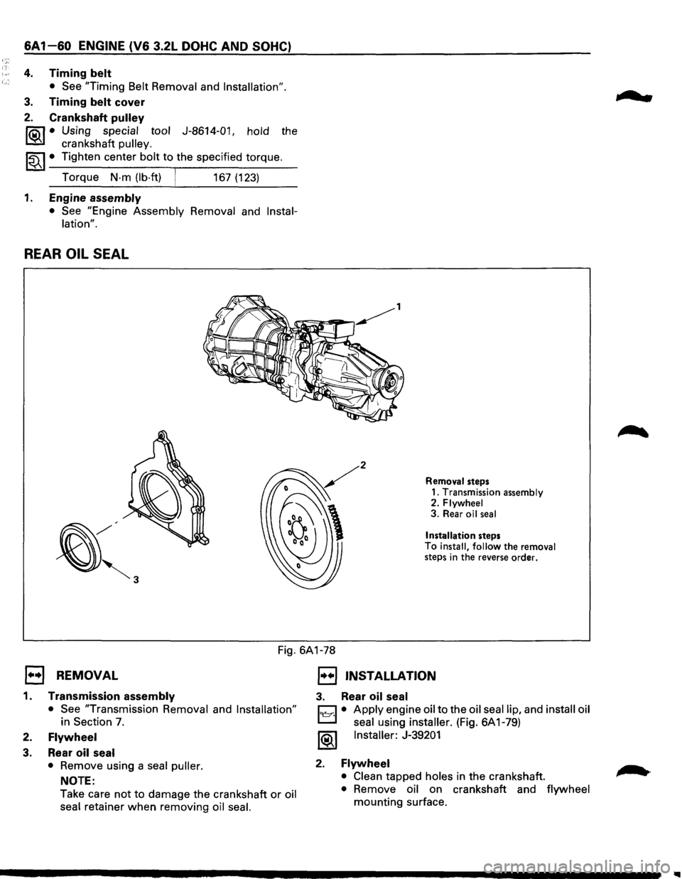
REAR OIL SEAL
Removal steps
1. Transmission assembly
2.
Flywheel 3. Rear oil seal
Installation steps To install, follow the removal
steps in the reverse order.
Fig. 6A1-78
E) REMOVAL
1. Transmission assembly
• See "Transmission Removal and Installation"
in Section 7.
2. Flywheel
3. Rear oil seal
•
Remove using a seal puller.
NOTE:
Take care
not to damage the crankshaft or oil
seal retainer
when removing oil seal.
1••1 INSTALLATION
3. Rear oil seal
C1 • Apply engine oil to the oil seal lip, and install oil
L:::l seal using installer. (Fig. 6A 1-79)
1®1 Installer: J-39201
2. Flywheel
• Clean tapped holes in the crankshaft.
• Remove oil on crankshaft and flywheel
mounting surface.
...
Page 619 of 1928
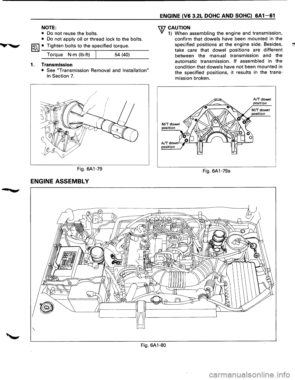
NOTE:
• Do not reuse the bolts.
•
Do not apply oil or thread lock to the bolts.
~~~ • Tighten bolts to the specified torque.
Torque
N·m (lb·ft) 54 (40)
1. Transmission
• See "Transmission Removal and Installation"
in Section 7.
Fig. 6A1-79
ENGINE ASSEMBL V
ENGINE (V6 3.2L DOHC AND SOHC) 6A 1-61
U7 CAUTION
VI 1) When assembling the engine and transmission,
confirm that
dowels have been mounted in the
specified positions at the engine side. Besides,
take care that
dowel positions are different
between the
manual transmission and the
automatic transmission.
If assembled in the
condition that
dowels have not been mounted in
the specified positions,
it results in the trans
mission broken.
M/Tdowel position
AIT dowe I Y~---...rr"lr-'1--' position
Fig. 6A1-79a
A/Tdowel position
Fig. 6A1-80