ISUZU TROOPER 1995 Workshop Manual
TROOPER 1995
ISUZU
ISUZU
https://www.carmanualsonline.info/img/61/57183/w960_57183-0.png
ISUZU TROOPER 1995 Workshop Manual
Page 622 of 1928
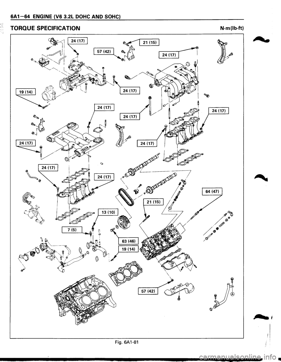
6A 1-64 ENGINE (V6 3.2L DOHC AND SOHC)
TORQUE SPECIFICATION N·m(lb·ft)
;?wt
Fig. 6A1-81
..
Page 623 of 1928
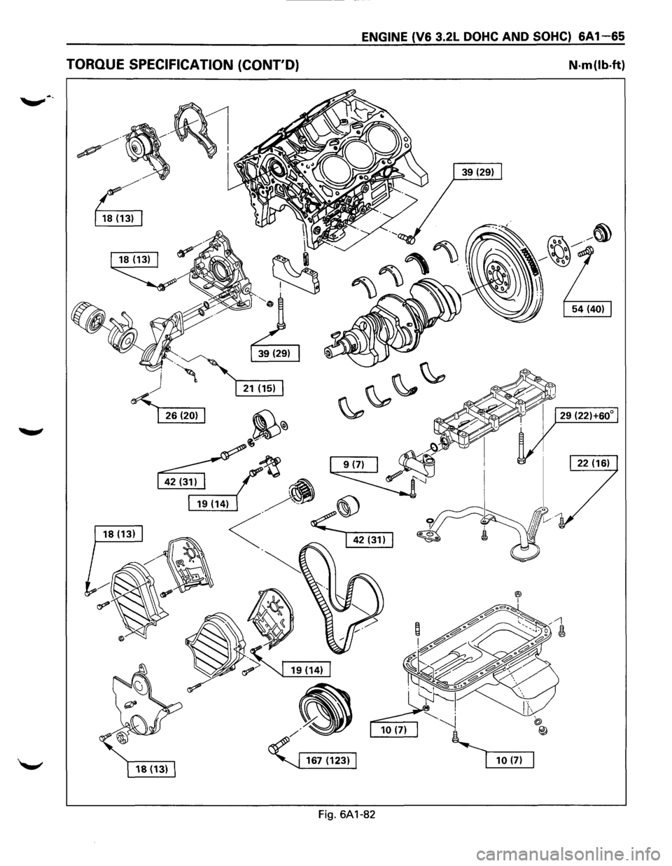
ENGINE (V6 3.2L DOHC AND SOHC) 6A1-65
TORQUE SPECIFICATION (CONT'D) N·m(lb·ft)
Fig. 6A1-82
Page 624 of 1928
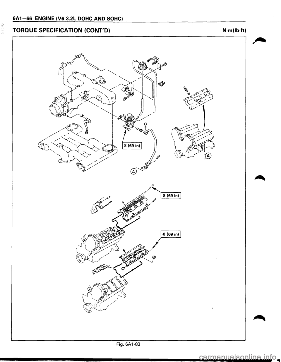
6A1-66 ENGINE (V6 3.2L DOHC AND SOHC)
TORQUE SPECIFICATION (CONT'D) N·m(lb·ft)
~. ~ 8(69in)
!1/" ';>~
~
··~· ~ -~\1W~ .· /
··~v·/~~~ (( .. ' ( /./ /'' ' . /~
·.··~ ··~rY;>""
.. ~
Fig. 6A1-83
..
Page 625 of 1928
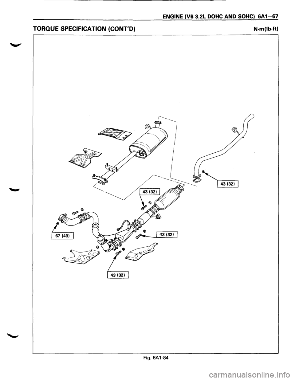
ENGINE (V6 3.2L DOHC AND SOHC) 6A1-67
TORQUE SPECIFICATION (CONT'D) N·m(lb·ft)
Fig. 6A1-84
Page 626 of 1928
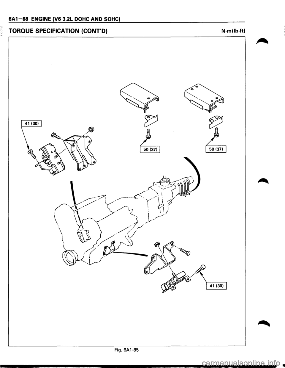
6A 1-68 ENGINE (V6 3.2L DOHC AND SOHC)
·~:; 1 TORQUE SPECIFICATION (CONT'D) N·m(lb·ft)
Fig. 6A1-85
Ill
Page 629 of 1928
ENGINE COOLING 68-1
SECTION 68
ENGINE COOLING
CONTENTS
General Description . . . . . . . . . . . . . . . . . . . . . . . . . . 68-1 Radiator . . . . . . . . . . . . . . . . . . . . . . . . . . . . . . . . . . . . . . 68-7
Diagnosis........................................ 68-3 Drive Belt Adjustment . . . . . . . . . . . . . . . . . . . . 68-1 0
On-Vehicle Service............................ 68-4 Main Data and Specifications .............. 68-12
Water Pump . . . . . . . . . . . . . . . . . . . . . . . . . . . . . . . . 68-4
Thermostat . . . . . . . . . . . . . . . . . . . . . . . . . . . . . . . . . . 68-6
Torque Specifications .................... 68-12
Special Tools ................................... 68-13
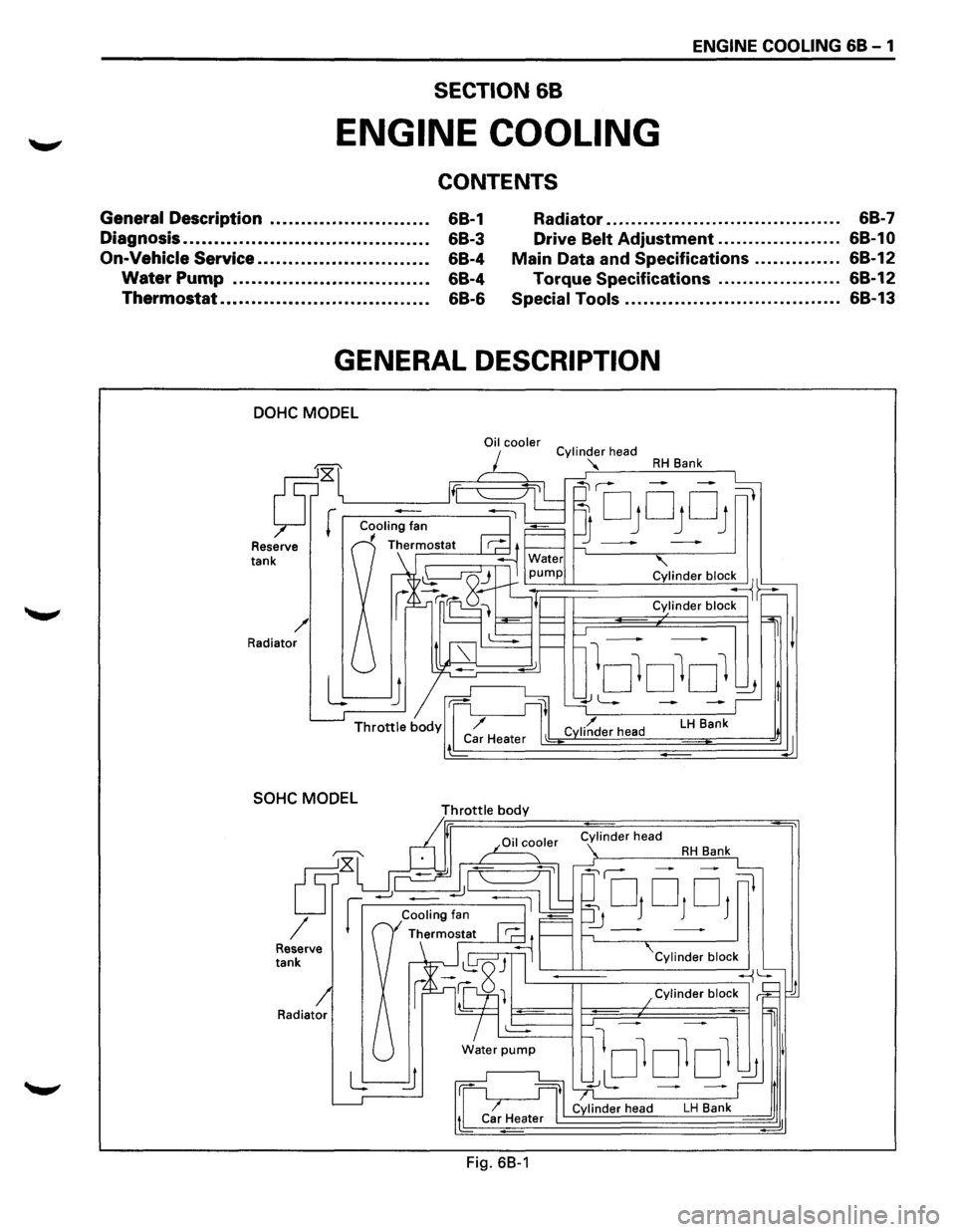
GENERAL DESCRIPTION
DOHC MODEL
Reserve tank
/ Radiator
SOHC MODEL
Radiator
Oil cooler
Throttle body
Fig. 68-1
Cylinder head
"'
RH Bank
' Cylinder bloc~~
Cylinder block
LH Bank
Cylinder block
~
lololol ~ I
~L: - -~,t
Cylinder head LH Bank d
d
Page 633 of 1928
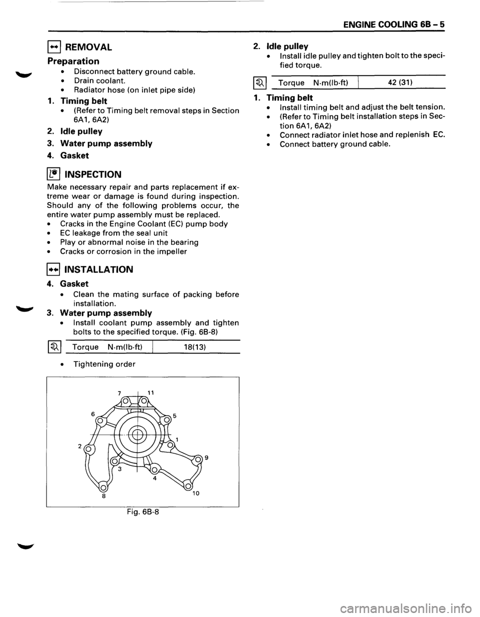
EJ REMOVAL
Preparation
• Disconnect battery ground cable.
•
Drain coolant.
•
Radiator hose (on inlet pipe side)
1. Timing belt
• (Refer to Timing belt removal steps in Section
6A1, 6A2)
2. Idle pulley
3. Water pump assembly
4. Gasket
~ INSPECTION
Make necessary repair and parts replacement if ex
treme wear or damage is found during inspection.
Should any of the following problems occur, the
entire water pump assembly must be replaced.
•
Cracks in the Engine Coolant (EC) pump body
• EC leakage from the seal unit
• Play or abnormal noise in the bearing
• Cracks or corrosion in the impeller
8 INSTALLATION
4. Gasket
• Clean the mating surface of packing before
installation.
3. Water pump assembly
• Install coolant pump assembly and tighten
bolts to the specified torque. (Fig. 68-8)
~~~ Torque N-m(lb-ft)
•
Tightening order
Fig. 68-8
18(13)
ENGINE COOLING 68-5
2. Idle pulley
• Install idle pulley and tighten bolt to the speci
fied
torque.
~~~ Torque N-m(lb·ft) 42 (31)
1. Timing belt
• Install timing belt and adjust the belt tension.
• (Refer to Timing belt installation steps in Sec
tion 6A1, 6A2)
• Connect radiator inlet hose and replenish EC.
• Connect battery ground cable.
Page 635 of 1928
B INSTALLATION
3. Thermostat
• Install thermostat into the thermostat hous
ing, making sure
that the jiggle valve in up
position.
2. Packing
RADIATOR
Reserve tank
6
ENGINE COOLING 68-7
1. Inlet pipe
• Connect inlet pipe and tighten bolts to the
specified torque.
I~~ Torque N·mOb·ft) 19 (14)
• Installation rubber hose
• Replenish Engine Coolant (EC)
• Start engine and check for EC leakage.
2
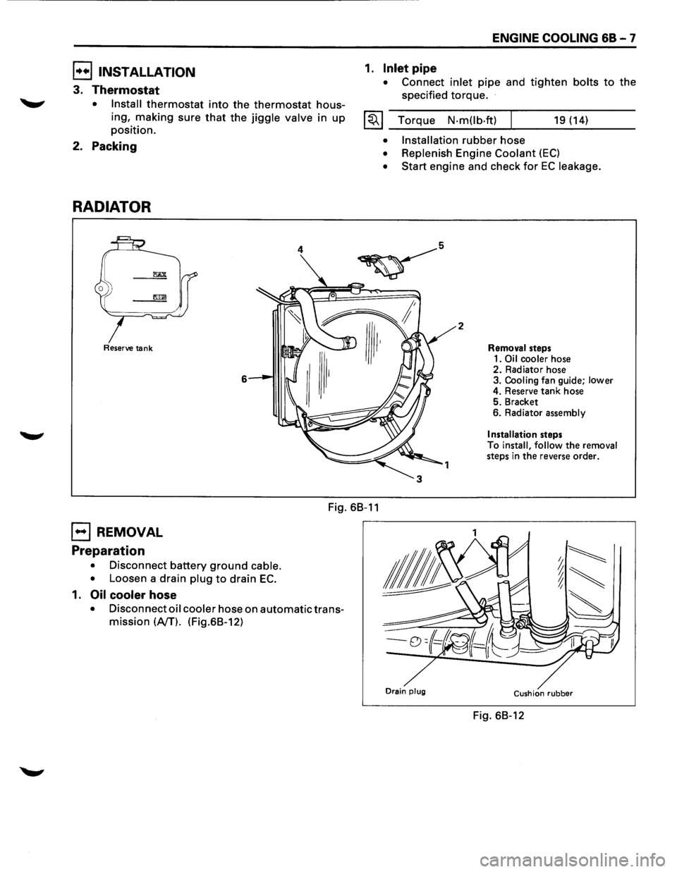
Removal steps
1.
Oil cooler hose 2. Radiator hose
3. Cooling fan guide; lower
4. Reserve tank hose
5. Bracket
6. Radiator assembly
Installation steps
To install, follow the removal
steps in the reverse order.
Fig. 68-11
EJ REMOVAL
Preparation
• Disconnect battery ground cable.
•
Loosen a drain plug to drain EC.
1. Oil cooler hose
• Disconnect oil cooler hose on automatic trans
mission
(NT). (Fig.68-12)
Drain plug Cushion rubber
Fig. 68-12
Page 639 of 1928
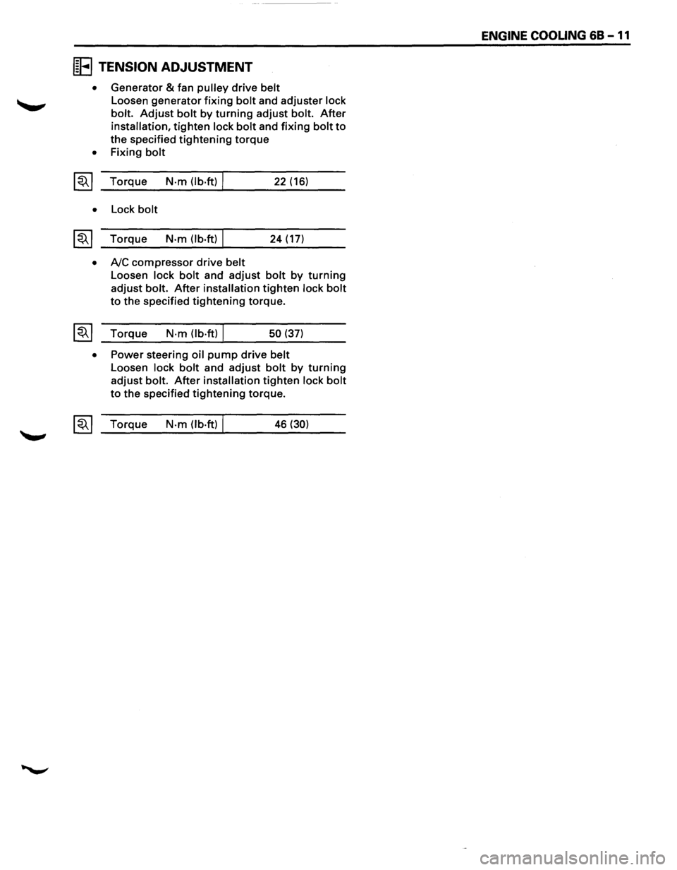
IE TENSION ADJUSTMENT
• Generator & fan pulley drive belt
Loosen generator fixing bolt and adjuster lock
bolt.
Adjust bolt by turning adjust bolt. After
installation, tighten lock bolt and fixing bolt to
the specified tightening torque
• Fixing bolt
~~~ Torque N·m (lb·ft) I 22 (16)
• Lock bolt
~~~ Torque N·m (lb.ft) I 24 (17)
• A/C compressor drive belt
Loosen lock bolt and adjust bolt by turning
adjust bolt. After installation tighten lock bolt
to the specified tightening torque.
~~~ Torque N·m (lb·ft) I 50 (37)
• Power steering oil pump drive belt
Loosen lock bolt and adjust bolt by turning
adjust bolt. After installation tighten lock bolt
to the specified tightening torque.
~~~ Torque N·m (lb·ft) I 46 (30)
ENGINE COOUNG 68 -11
Page 640 of 1928
68 -12 ENGINE COOLING
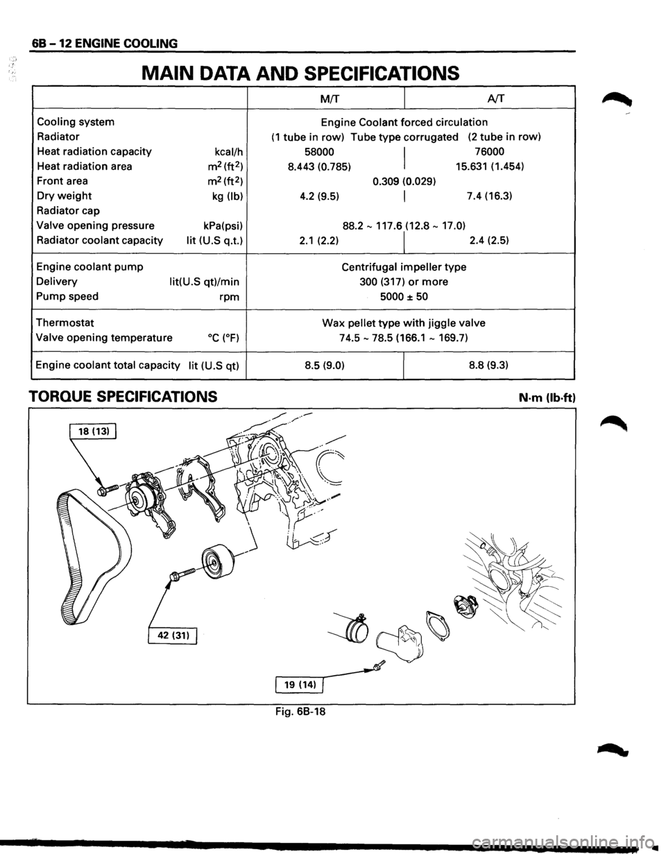
MAIN DATA AND SPECIFICATIONS
M!T I AfT
Cooling system
Engine Coolant forced circulation
Radiator (1 tube in row) Tube type corrugated (2 tube in row)
Heat radiation capacity
kcal/h 58000
I
76000
Heat radiation area m2 (ft2)
8.443 (0.785) 15.631 (1.454)
Front area m2 (ft2) 0.309 (0.029)
Dry weight kg (lb) 4.2 (9.5) I 7.4 (16.3)
Radiator cap
Valve opening pressure kPa(psi) 88.2-117.61(12.8-17.0)
Radiator coolant capacity lit (U.S q.t.) 2.1 (2.2) 2.4 (2.5)
Engine
coolant pump Centrifugal impeller type
Delivery lit(U.S qt)/min 300 (317) or more
Pump speed rpm 5000 ±50
Thermostat Wax pellet type with jiggle valve
Valve
opening temperature oc (oF) 74.5-78.5 (166.1-169.7)
Engine
coolant total capacity lit (U.S qt) 8.5 (9.0) I 8.8
(9.3)
TORQUE SPECIFICATIONS N-m (lb·ft)
Fig. 68-18
..