torque ISUZU TROOPER 1995 Workshop Manual
[x] Cancel search | Manufacturer: ISUZU, Model Year: 1995, Model line: TROOPER, Model: ISUZU TROOPER 1995Pages: 1928
Page 803 of 1928
New or service sensors will already have the
compound
applied to the threads. If a sensor is
removed
from an engine and iffor any reason it
is to be reinstalled, the threads must have anti
seize compound
applied before reinstallation.
•
Apply anti-seize compound or equivalent to
threads of oxygen sensor if necessary.
• Tighten the oxygen sensor to the specified
torque.
1~1 Torque N·m (lb·ft) 55 (40)
1. H02S wiring connector
THROTTLE POSITION (TP) SENSOR
Fig. 6E2-59
E) REMOVAL
Preparation: • Battery negative cable.
1. Throttle Position (TP) sensor wiring connector
2. TP sensor fixing screw
3. TP sensor
I••IINSTALLATION
3. TP sensor
2. TP sensor fixing screw
• Tighten the fixing screw to the specified torque.
~~~ Torque N·m (lb·in) I 2 (18)
• Use a "Scan tool" to check TP sensor output
voltage with throttle closed, should be under
0.85 volts. If over 0.85 volts, check for binding
throttle shaft, or TP sensor lever. If all OK,
replace TP sensor.
1.
TP sensor wiring connector
DRIVEABILITY AND EMISSIONS 6E2-1 07
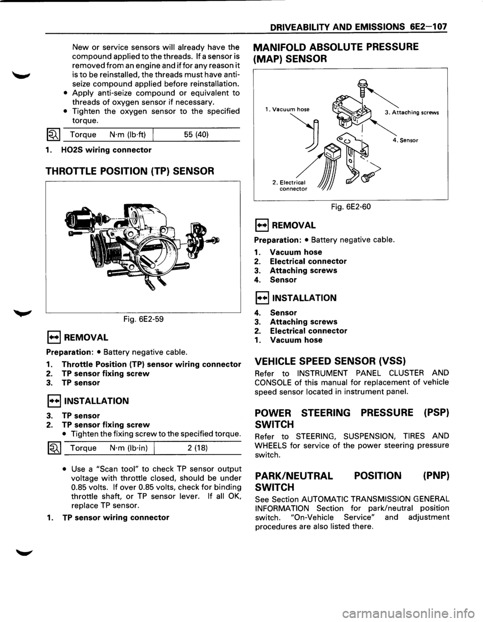
MANIFOLD ABSOLUTE PRESSURE
(MAP) SENSOR
1. Vacuum hose
) 0~
2 .• ,.~,,~,~
conne~ JJJ
4. Sensor
Fig. 6E2-60
E) REMOVAL
Preparation: • Battery negative cable.
1. Vacuum hose
2. Electrical connector
3. Attaching screws
4. Sensor
I••IINSTALLATION
4. Sensor
3. Attaching screws
2. Electrical connector
1. Vacuum hose
VEHICLE SPEED SENSOR (VSS)
Refer to INSTRUMENT PANEL CLUSTER AND
CONSOLE of this manual for replacement of vehicle
speed sensor located in instrument panel.
POWER STEERING PRESSURE (PSP)
SWITCH
Refer to STEERING, SUSPENSION, TIRES AND
WHEELS for service of the power steering pressure
switch.
PARK/NEUTRAL
SWITCH POSITION
(PNP}
See
Section AUTOMATIC TRANSMISSION GENERAL
INFORMATION Section for park/neutral position
switch.
"On-Vehicle Service" and adjustment
procedures are
also listed there.
Page 821 of 1928
Names of component parts can be found on the
numbered
list on the disassembled view (Fig. 6E2-78).
Fig. 6E2-78
Throttle Body (TB)
5
6
2
DRIVEABILITY AND EMISSIONS 6E2-125
m • The throttle bore and valve deposits may be
t..a.l cleaned on-vehicle, using carburetor cleaner
and a shop towel. Do not use a cleaner that
contains
methyl ethyl ketone. It is an extremely
strong solvent, and
not necessary for this type
of deposit.
• The Throttle Body (TB) metal parts may be
cleaned following disassembly, in a cold
immersion-type cleaner.
NOTE:
The Throttle Position Sensor and Idle Air
Control
valve should NOT come in contact with
solvent or
cleaner, as they may be damaged.
1
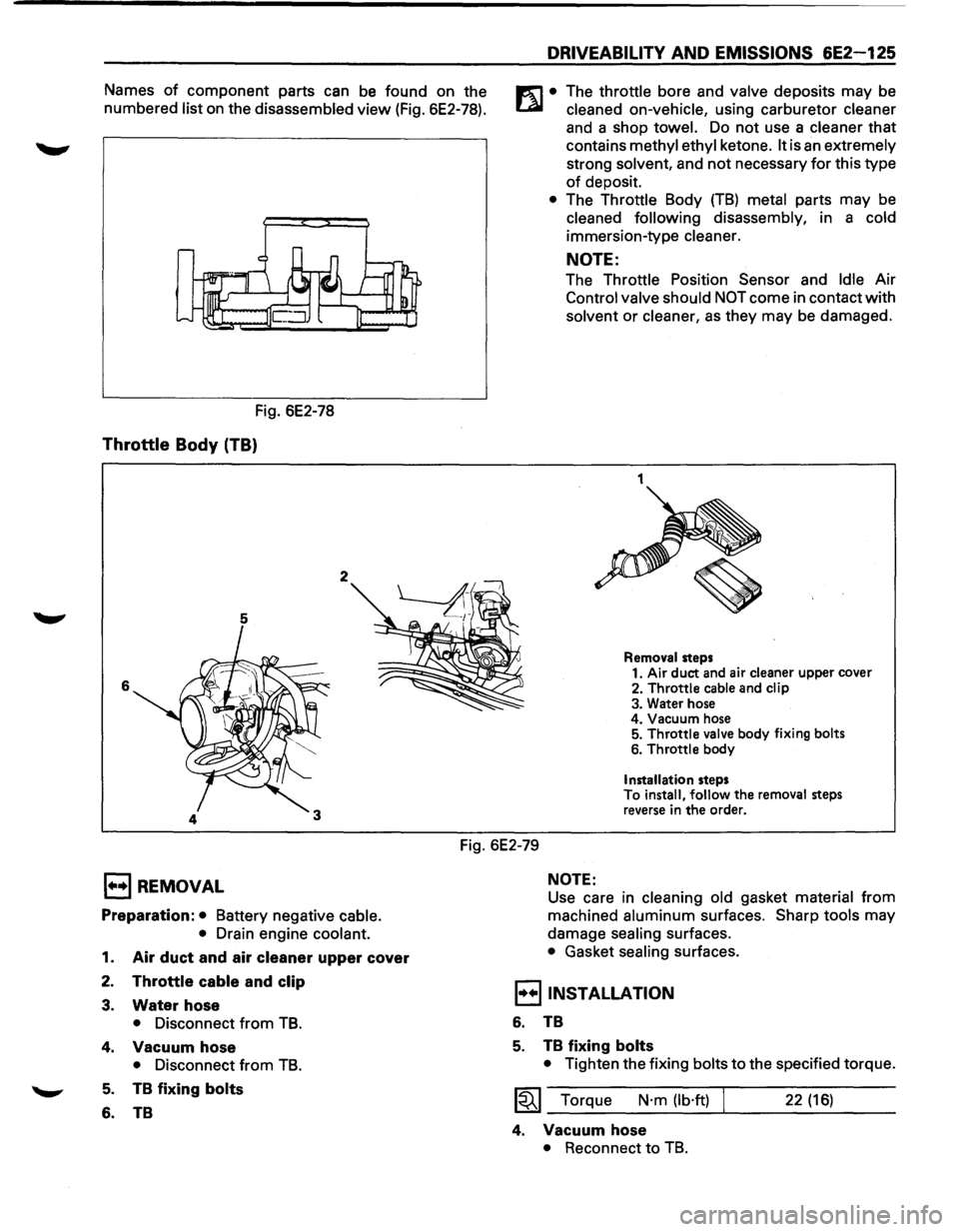
Removal steps
1. Air duct and air cleaner upper cover
2.
Throttle cable and clip
3. Water hose
4. Vacuum hose
5.
Throttle valve body fixing bolts
6. Throttle body
Installation steps
To install, follow the removal steps
reverse in
the order.
Fig. 6E2-79
1••1 REMOVAL
Preparation: • Battery negative cable.
•
Drain engine coolant.
1. Air duct and air cleaner upper cover
2. Throttle cable and clip
3. Water hose
• Disconnect from TB.
4. Vacuum hose
• Disconnect from TB.
5. TB fixing bolts
6. TB
NOTE:
Use care in cleaning old gasket material from
machined
aluminum surfaces. Sharp tools may
damage
sealing surfaces.
• Gasket sealing surfaces.
I••IINSTALLATION
6. TB
5. TB fixing bolts
• Tighten the fixing bolts to the specified torque.
~~~ Torque N·m (lb·ft) 22 (16)
4. Vacuum hose
• Reconnect to TB.
Page 822 of 1928
6E2-126 DRIVEABILITV AND EMISSIONS
3. Water hoses
• Reconnect to throttle body.
2. Throttle cable and clip
1. Air duct and air cleaner upper cover
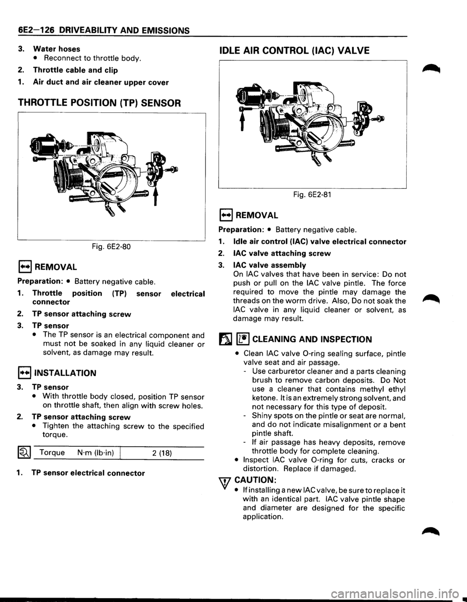
THROTTLE POSITION (TP) SENSOR
Fig. 6E2-80
1••1 REMOVAL
Preparation: • Battery negative cable.
1. Throttle position (TP) sensor electrical
connector
2. TP sensor attaching screw
3. TP sensor
• The TP sensor is an electrical component and
must not be soaked in any liquid cleaner or
solvent, as damage may result.
I••IINSTALLATION
3. TP sensor
• With throttle body closed, position TP sensor
on throttle shaft, then align
with screw holes.
2. TP sensor attaching screw
• Tighten the attaching screw to the specified
torque.
~~~ Torque N·m (lb·in) 2 (18)
1. TP sensor electrical connector
IDLE AIR CONTROL (lAC) VALVE
Fig. 6E2-81
E) REMOVAL
Preparation: • Battery negative cable.
1. Idle air control (lAC) valve electrical connector
2.
lAC valve attaching screw
3. lAC valve assembly
On lAC valves that have been in service: Do not
push or pull on the lAC valve pintle. The force
required
to move the pintle may damage the
threads on the
worm drive. Also, Do not soak the
lAC valve in any liquid cleaner or solvent, as
damage may result.
f}J [1!) CLEANING AND INSPECTION
• Clean lAC valve 0-ring sealing surface, pintle
valve seat and air passage.
- Use carburetor cleaner and a parts cleaning
brush
to remove carbon deposits. Do Not
use a cleaner
that contains methyl ethyl
ketone.
It is an extremely strong solvent, and
not necessary for this type of deposit.
-
Shiny spots on the pintle or seat are normal,
and
do not indicate misalignment or a bent
pintle shaft.
-
If air passage has heavy deposits, remove
throttle
body for complete cleaning.
• Inspect lAC valve 0-ring for cuts, cracks or
distortion. Replace
if damaged.
WCAUTION:
VI • If installing a new lAC valve, be sure to replace it
with an identical part. lAC valve pintle shape
and diameter are designed
for the specific
application.
Page 828 of 1928
6E2-132 DRIVEABILITV AND EMISSIONS
CHART C-20
INDUCTION AIR CONTROL PLATE SYSTEM CHECK
(DOHC ONLY)
Circuit Description:
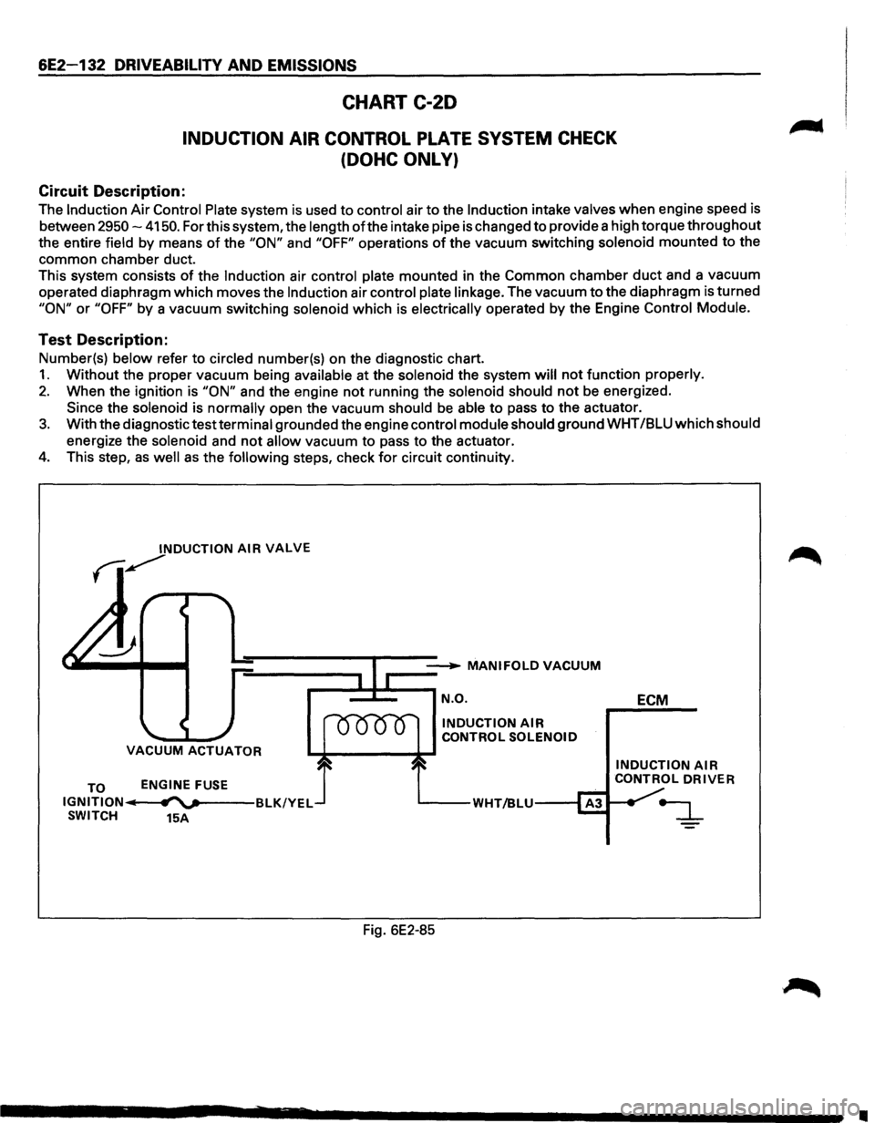
The Induction Air Control Plate system is used to control air to the Induction intake valves when engine speed is
between
2950-4150. For this system, the length of the intake pipe is changed to provide a high torque throughout
the entire field by means
of the "ON" and "OFF" operations of the vacuum switching solenoid mounted to the
common chamber duct.
This system consists
of the Induction air control plate mounted in the Common chamber duct and a vacuum
operated diaphragm which moves the
Induction air control plate linkage. The vacuum to the diaphragm is turned
"ON" or "OFF" by a vacuum switching solenoid which is electrically operated by the Engine Control Module.
Test Description:
Number(s) below refer to circled number(s) on the diagnostic chart.
1. Without the proper vacuum being available at the solenoid the system will not function properly.
2. When the ignition is "ON" and the engine not running the solenoid should not be energized.
Since the solenoid is normally open the vacuum should
be able to pass to the actuator.
3. With the diagnostic test terminal grounded the engine control module should ground WHT /BLU which should
energize the solenoid and
not allow vacuum to pass to the actuator.
4. This step, as well as the following steps, check for circuit continuity.
INDUCTION AIR VALVE
fi~
__ __...._ MANIFOLDVACUUM
r-=~=-~ N.O.
VACUUM ACTUATOR
TO IGNITION IIi SWITCH ENGINE
FUSE
fl""'v---BLK/YEL
15A
INDUCTION AIR CONTROL
SOLENOID
'----WHT/BLU---1
Fig. 6E2-85 ECM
INDUCTION AIR CONTROL DRIVER
•
Page 863 of 1928
ENGINE EXHAUST (V6 3.2L) 6F-1
SECTION 6F
ENGINE EXHAUST (V6 3.2L)
\fl CAUTION:
VI Exhaust system components must have enough clearance from the upderbody to prevent overheating the
floor pan and damaging the passenger compartment, insulation
and trim materials.
CONTENTS
General Description . . . . . . . . . . . . . . . . . . . . 6F,....1
Hangers ........................... , ... ..-6f-2
Three Way Catalytic Converter ....• ·; ~. 6F-2
Gasket . . . . . . . . . . . . . . . . . . . . . . . . . . . . . 6F-2
On-Vehicle Service ........ , . . . . . . . . . . . 6F-3
Front Exhaust Pipe ... , " ;< . . . . . . . . . . . . 6F-3
Center Exhaust Pipe.. .. : -. . . . . . . . . . . . . . . . 6F-4
.. .r·
Three Way Catalytic Converter . . . . . . . . . 6F-5
Pre Catalytic Converter . . . . . . . . . . . . . . . 6F-6
Exhaust Silencer . . . . . . . . . . . . . . . . . . . . . 6F-7
Rear Exhaust Pipe . . . . . . . . . . . . . . . . . . . . 6F-8
Exhaust Pipe Mounting Rubber . . . . . . . . 6F-9
Main Data and Specifications ........... 6F-10
Torque Specifications ............... 6F-10
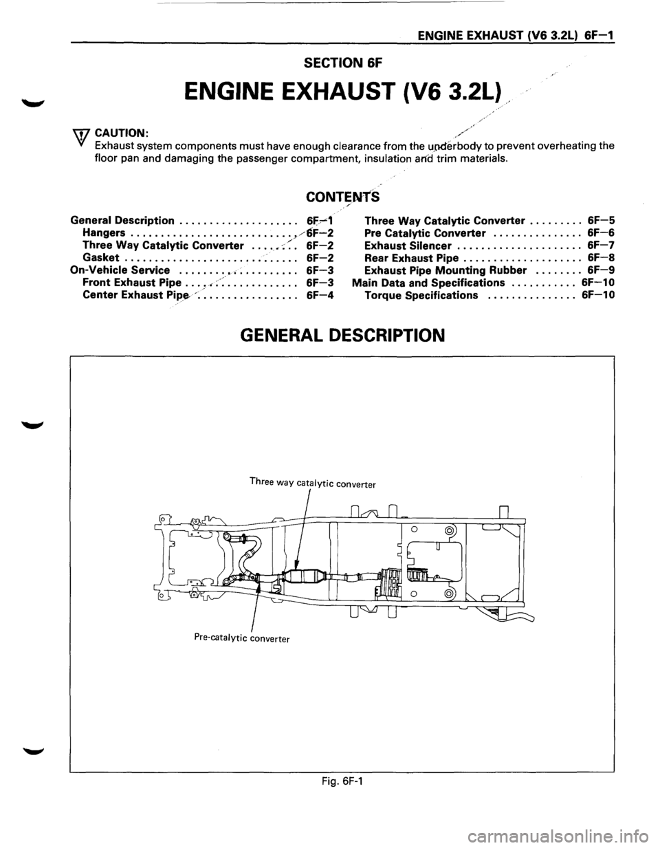
GENERAL DESCRIPTION
Three way catalytic converter
Pre-catalytic converter
Fig. 6F-1
Page 865 of 1928
ENGINE EXHAUST (V6 3.2L) &F-3
ON-VEHICLE SERVICE
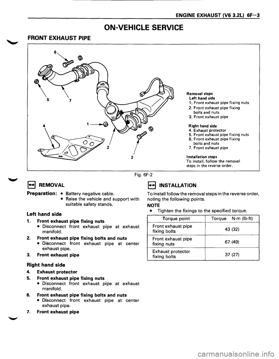
FRONT EXHAUST PIPE
2
Removal steps
Left hand side
1.
Front exhaust pipe fixing nuts
2. Front exhaust pipe fixing
bolts and nuts
3. Front exhaust pipe
Right hand side
4. Exhaust
protector 5. Front exhaust pipe fixing nuts 6. Front exhaust pipe fixing bolts and nuts
7. Front exhaust pipe
Installation steps
To install, follow the removal steps in the reverse order.
Fig. 6F-2
EJ REMOVAL
Preparation: • Battery negative cable.
•
Raise the vehicle and support with
suitable safety stands.
Left hand side
1. Front exhaust pipe fixing nuts
• Disconnect front exhaust pipe at exhaust
manifold.
2. Front exhaust pipe fixing bolts and nuts
• Disconnect front exhaust pipe at center
exhaust pipe.
3.
Front exhaust pipe
Right hand side
4. Exhaust protector
5. Front exhaust pipe fixing nuts
• Disconnect front exhaust pipe at exhaust
manifold.
6. Front exhaust pipe fixing bolts and nuts
• Disconnect front exhaust pipe at center
exhaust pipe.
1. Front exhaust pipe
1•+1 INSTALLATION
To install follow the removal steps in the reverse order,
noting the
following points.
NOTE
• Tighten the fixings to the specified torque.
Torque point Torque
N·m (lb·ft)
Front exhaust pipe
43 (32) fixing bolts
Front exhaust pipe 67 (49) fixing nuts
Exhaust protector
37 (27) fixing bolts
Page 866 of 1928
&F-4 ENGINE EXHAUST (V6 3.2L)
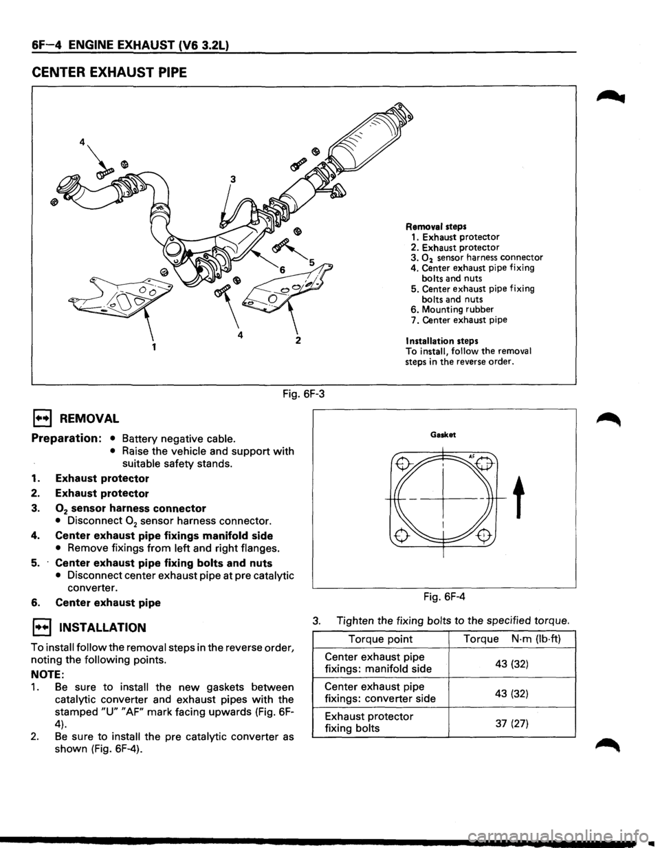
CENTER EXHAUST PIPE
4
1
Fig. 6F-3
E3 REMOVAL
Preparation: • Battery negative cable.
• Raise the vehicle and support with
suitable safety stands.
1. Exhaust protector
2. Exhaust protector
3. 02 sensor harness connector
• Disconnect 02 sensor harness connector.
4. Center exhaust pipe fixings manifold side
• Remove fixings from left and right flanges.
5. Center exhaust pipe fixing bolts and nuts
• Disconnect center exhaust pipe at pre catalytic
converter.
6. Center exhaust pipe
Removal steps 1. Exhaust protector
2. Exhaust protector
3.
02 sensor harness connector
4. Center exhaust pipe fixing
bolts and nuts
5. Center exhaust pipe fixing
bolts and nuts
6. Mounting rubber
7. Center exhaust pipe
Installation steps
To install, follow the removal
steps in the reverse order.
Gasket
t
Fig. 6F-4
1••1 INSTALLATION 3. Tighten the fixing bolts to the specified torque.
To
install follow the removal steps in the reverse order,
noting the
following points.
NOTE:
1. Be sure to install the new gaskets between
catalytic converter and exhaust pipes
with the
stamped
"U" "AF" mark facing upwards (Fig. 6F-
4).
2. Be sure to install the pre catalytic converter as
shown (Fig. 6F-4). Torque
point
Center exhaust pipe
fixings: manifold side
Center exhaust pipe
fixings: converter side
Exhaust protector
fixing bolts Torque
N·m
(lb·ft)
43 (32)
43 (32)
37 (27)
Page 867 of 1928
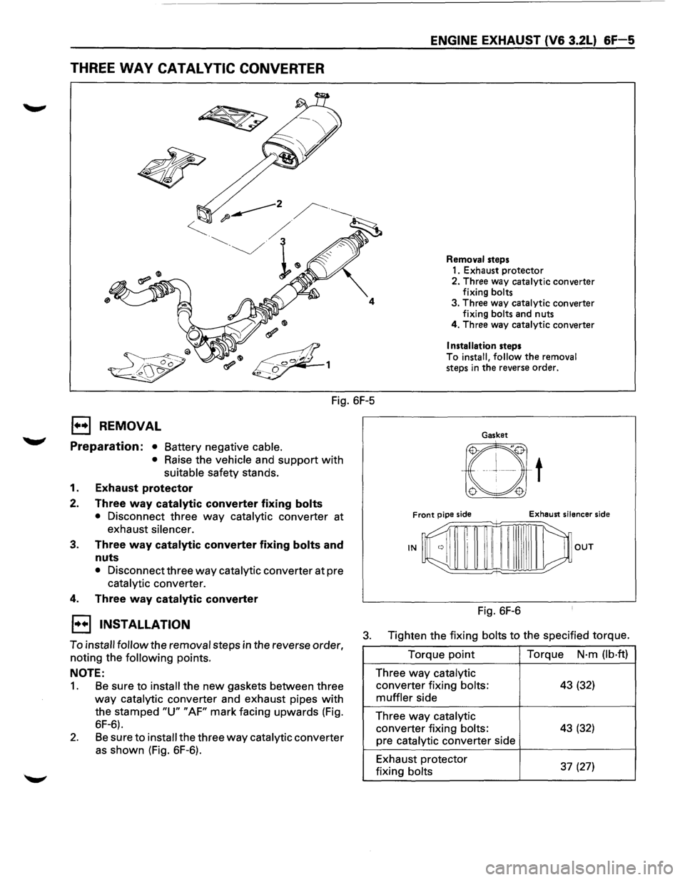
THREE WAY CATALYTIC CONVERTER
Fig. 6F-5
1••1 REMOVAL
Preparation: • Battery negative cable.
•
Raise the vehicle and support with
suitable safety stands.
1. Exhaust protector
2. Three way catalytic converter fixing bolts
• Disconnect three way catalytic converter at
exhaust
silencer.
3. Three way catalytic converter fixing bolts and
nuts
• Disconnect three way catalytic converter at pre
catalytic converter.
4. Three way catalytic converter
ENGINE EXHAUST (V6 3.2L) &F-5
Removal steps
1. Exhaust protector
2. Three way catalytic converter
fixing
bolts 3. Three way catalytic converter
fixing bolts and nuts
4. Three way catalytic converter
Installation steps
To
install, follow the removal steps in the reverse order.
Gasket
t
Front pipe side Exhaust silencer side
--;::;;;=;;:::;;=;;:::;;±:;;:~mn=i:'--
IN OUT
Fig. 6F-6
1••1 INSTALLATION
To install follow the removal steps in the reverse order,
noting the
following points.
3. Tighten the fixing bolts to the specified torque.
NOTE:
1. Be sure to install the new gaskets between three
way catalytic converter and exhaust pipes with
the stamped "U" "AF" mark facing upwards (Fig.
6F-6).
2. Be sure to install the three way catalytic converter
as shown (Fig. 6F-6). Torque
point
Three way catalytic
converter
fixing bolts:
muffler side
Three
way catalytic
converter fixing bolts:
pre catalytic converter side
Exhaust protector
fixing
bolts
Torque N·m (lb·ft)
43 (32)
43 (32)
37
(27)
Page 868 of 1928
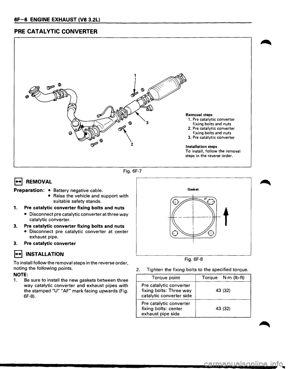
6F-6 ENGINE EXHAUST (V6 3.2L)
PRE CATAL VTIC CONVERTER
2
Fig. 6F-7
1••1 REMOVAL
Preparation: • Battery negative cable.
•
Raise the vehicle and support with
suitable safety stands.
1. Pre catalytic converter fixing bolts and nuts
• Disconnect pre catalytic converter at three way
catalytic converter.
3. Pre catalytic converter fixing bolts and nuts
• Disconnect pre catalytic converter at center
exhaust pipe.
3. Pre catalytic converter
1••1 INSTALLATION
Removal steps
1. Pre catalytic converter
fixing bolts and nuts
2. Pre catalytic converter
fixing bolts and
nuts 3. Pre catalytic converter
Installation steps To install, follow the removal
steps in the reverse order.
Gasket
t
Fig. 6F-8
To install follow the removal steps in the reverse order,
noting the following points. 2. Tighten the fixing bolts to the specified torque.
NOTE:
1. Be sure to install the new gaskets between three
way catalytic converter and exhaust pipes with
the stamped "U" "AF" mark facing upwards (Fig.
6F-8). Torque
point
Pre catalytic converter
fixing
bolts: Three way
catalytic converter side
Pre catalytic converter
fixing
bolts: center
exhaust pipe side Torque
N·m
(lb·ft)
43 (32)
43 (32)
Page 869 of 1928
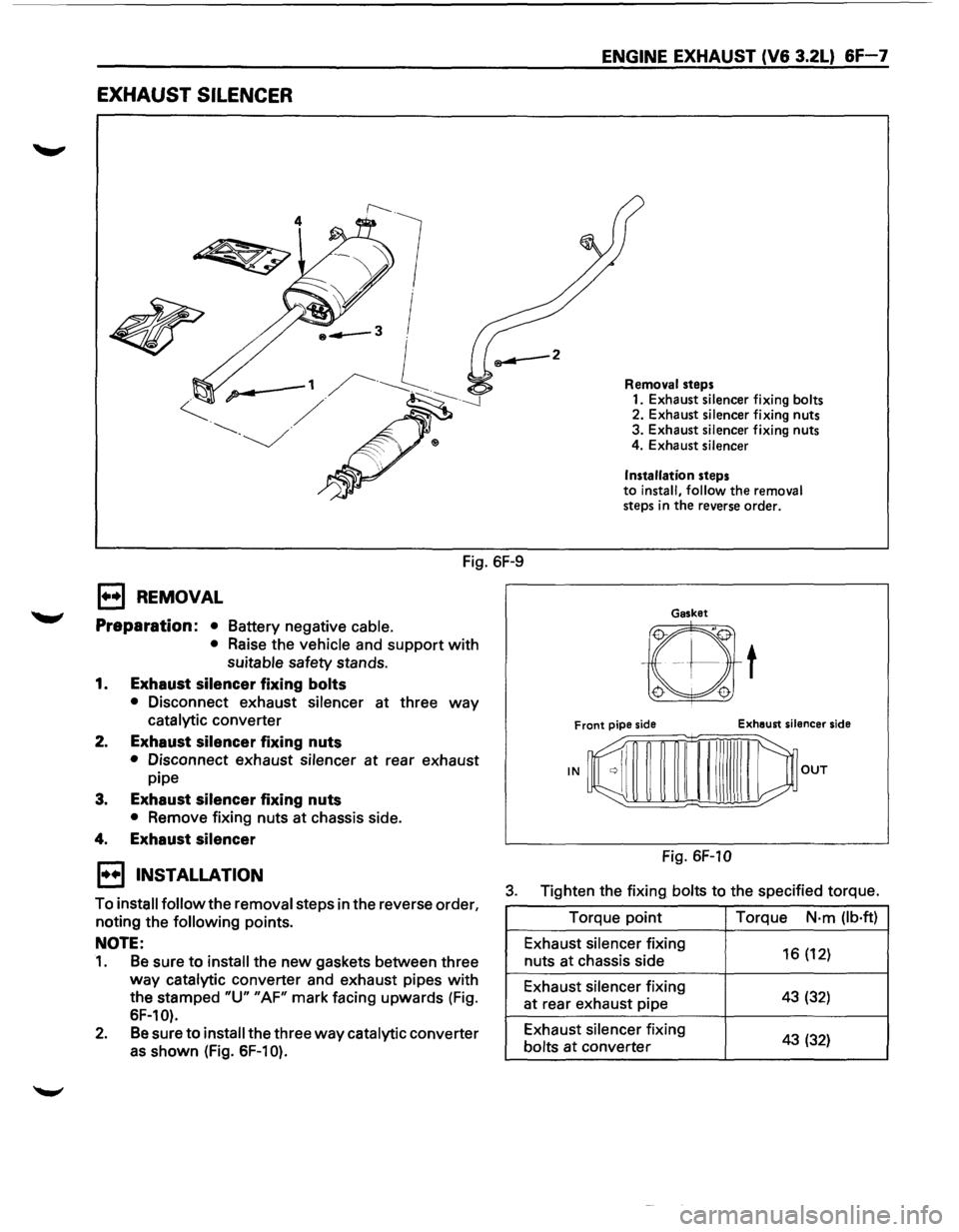
EXHAUST SILENCER
4
Fig. 6F-9
E) REMOVAL
Preparation: •
Battery negative cable.
• Raise the vehicle and support with
suitable safety stands.
1. Exhaust silencer fixing bolts
• Disconnect exhaust silencer at three way
catalytic converter
2. Exhaust silencer fixing nuts
• Disconnect exhaust silencer at rear exhaust
pipe
3. Exhaust silencer fixing nuts
• Remove fixing nuts at chassis side.
4. Exhaust silencer
ENGINE EXHAUST (V6 3.2L) 6F-7
Removal steps
1. Exhaust silencer fixing bolts 2. Exhaust silencer fixing nuts
3. Exhaust silencer fixing nuts
4. Exhaust silencer
Installation
steps to install, follow the removal steps in the reverse order.
Gasket
Fig. 6F-10
1••1 INSTALLATION
To install follow the removal steps in the reverse order,
noting the following points.
3. Tighten the fixing bolts to the specified torque.
NOTE:
1. Be sure to install the new gaskets between three
way catalytic converter and exhaust pipes with
the stamped "U" "AF" mark facing upwards (Fig.
SF-10).
2. Be sure to install the three way catalytic converter
as shown (Fig. SF-10).
Torque point
Exhaust silencer fixing
nuts at chassis side
Exhaust silencer fixing
at rear exhaust pipe
Exhaust silencer fixing
bolts
at converter Torque
N·m
(lb·ft)
16 (12)
43 (32)
43 (32)